EP0391755A2 - Bildanzeigesystem - Google Patents
Bildanzeigesystem Download PDFInfo
- Publication number
- EP0391755A2 EP0391755A2 EP90400570A EP90400570A EP0391755A2 EP 0391755 A2 EP0391755 A2 EP 0391755A2 EP 90400570 A EP90400570 A EP 90400570A EP 90400570 A EP90400570 A EP 90400570A EP 0391755 A2 EP0391755 A2 EP 0391755A2
- Authority
- EP
- European Patent Office
- Prior art keywords
- memory
- images
- sub
- information
- image
- Prior art date
- Legal status (The legal status is an assumption and is not a legal conclusion. Google has not performed a legal analysis and makes no representation as to the accuracy of the status listed.)
- Withdrawn
Links
Images
Classifications
-
- H—ELECTRICITY
- H04—ELECTRIC COMMUNICATION TECHNIQUE
- H04N—PICTORIAL COMMUNICATION, e.g. TELEVISION
- H04N9/00—Details of colour television systems
- H04N9/12—Picture reproducers
- H04N9/30—Picture reproducers using solid-state colour display devices
-
- G—PHYSICS
- G09—EDUCATION; CRYPTOGRAPHY; DISPLAY; ADVERTISING; SEALS
- G09G—ARRANGEMENTS OR CIRCUITS FOR CONTROL OF INDICATING DEVICES USING STATIC MEANS TO PRESENT VARIABLE INFORMATION
- G09G3/00—Control arrangements or circuits, of interest only in connection with visual indicators other than cathode-ray tubes
- G09G3/20—Control arrangements or circuits, of interest only in connection with visual indicators other than cathode-ray tubes for presentation of an assembly of a number of characters, e.g. a page, by composing the assembly by combination of individual elements arranged in a matrix no fixed position being assigned to or needed to be assigned to the individual characters or partial characters
- G09G3/22—Control arrangements or circuits, of interest only in connection with visual indicators other than cathode-ray tubes for presentation of an assembly of a number of characters, e.g. a page, by composing the assembly by combination of individual elements arranged in a matrix no fixed position being assigned to or needed to be assigned to the individual characters or partial characters using controlled light sources
- G09G3/30—Control arrangements or circuits, of interest only in connection with visual indicators other than cathode-ray tubes for presentation of an assembly of a number of characters, e.g. a page, by composing the assembly by combination of individual elements arranged in a matrix no fixed position being assigned to or needed to be assigned to the individual characters or partial characters using controlled light sources using electroluminescent panels
- G09G3/32—Control arrangements or circuits, of interest only in connection with visual indicators other than cathode-ray tubes for presentation of an assembly of a number of characters, e.g. a page, by composing the assembly by combination of individual elements arranged in a matrix no fixed position being assigned to or needed to be assigned to the individual characters or partial characters using controlled light sources using electroluminescent panels semiconductive, e.g. using light-emitting diodes [LED]
-
- G—PHYSICS
- G09—EDUCATION; CRYPTOGRAPHY; DISPLAY; ADVERTISING; SEALS
- G09G—ARRANGEMENTS OR CIRCUITS FOR CONTROL OF INDICATING DEVICES USING STATIC MEANS TO PRESENT VARIABLE INFORMATION
- G09G3/00—Control arrangements or circuits, of interest only in connection with visual indicators other than cathode-ray tubes
- G09G3/20—Control arrangements or circuits, of interest only in connection with visual indicators other than cathode-ray tubes for presentation of an assembly of a number of characters, e.g. a page, by composing the assembly by combination of individual elements arranged in a matrix no fixed position being assigned to or needed to be assigned to the individual characters or partial characters
- G09G3/2007—Display of intermediate tones
- G09G3/2018—Display of intermediate tones by time modulation using two or more time intervals
Definitions
- the invention relates to a system for viewing images, in particular video images over a large area where the locations of the pixels are materialized by light components, such as light-emitting diodes, arranged in a matrix configuration, on said surface. .
- Information display systems are known by light-emitting diodes, generally having a display surface in the form of an elongated rectangle, to allow the display of scrolling information.
- Each pixel of the image is materialized by a light-emitting diode which is on or off.
- These systems are particularly useful in public places, as the light emitting diodes are visible from a distance.
- their brightness is not adjustable, which has so far limited their use to the representation of written messages, possibly a few drawings.
- the invention aims to implement the technology of display panels composed of light elements such as light emitting diodes, for the representation of moving images. Any video sequence is broken down, as everyone knows, into a sequence of still images following one another at a given rate, for example 25 frames per second.
- the basic principle of the invention consists in representing each fixed image of this succession of images (in the time allotted to it) by a succession of "sub-images" for which the diodes are on or off, the retinal persistence "integrating" the superposition of all these sub-images to reconstruct the still image.
- the brightness of a point in the image is therefore translated by the number of ignitions of the corresponding light-emitting diode, in the succession of said sub-images.
- a number of ignitions in a sequence of sub-images of the same still image is translated by effective ignitions of each diode in a predetermined number of sub-images of said sequence.
- the invention therefore relates to an image display system comprising at least one panel of light components such as light-emitting diodes, arranged in a matrix configuration on a display surface, said diodes being controlled by respective outputs of shift registers connected in cascade, characterized in that it comprises: a memory receiving digitized information representative of at least a fraction of video image and corresponding to a predetermined number of light components, the content of said memory being renewed at a rate of succession of said images, a conversion table, forming read only memory, connected on the one hand to said memory and on the other hand to a sequencer for receiving cyclically information from said memory and sequencing orders, the output of this conversion table being connected to said shift register cascade, and - in that said conversion table is programmed to generate, at its output, information representative of sub-images at the rate of said sequencer, each light component being switched on during a cycle of sub-images a number of times and at times predetermined at least in part by the value of corresponding information in said memory.
- the information taken from said memory to address said conversion table is advantageously supplemented by information representative of the ambient brightness, by means sensitive to the ambient brightness, comprising for example a photosensitive transducer and an analog-digital converter.
- information representative of the ambient brightness by means sensitive to the ambient brightness, comprising for example a photosensitive transducer and an analog-digital converter.
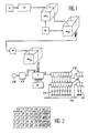
- the installation notably includes a video signal source V, for example a camera or a video recorder, a digitizing unit N receiving said video signal from the video signal source and delivering a corresponding signal where each pixel of the video image is coded in digital form, memories M1, M2, M3 and a display table constituted by a plurality of light-emitting diodes 11 arranged side by side in a matrix configuration.
- the digital information delivered by the digitizing unit N is sent to a first memory M1 in which information representative of a succession of images is stored cyclically.
- the information in the memory M1 is renewed at a "cinematic" rate here chosen equal to 25 images per second.
- the sampling of the video signal by the digitizing unit N is here carried out on 3 bits.
- the luminance of each pixel can take eight different values, from 0 to 7.
- the memory M1 has been diagrammed with three "planes", each plan containing the storage units necessary for the bits of the same weight of all the pixels of the video image.
- the information is read and transferred, at least partially, into a memory M2, under the control of a logic controller A.
- the renewal of the information in the memory M2 is done at the same rate as in the memory M1.
- the memory M2 is a “formatting” and processing memory which makes it possible to produce an image composed from the video image available in the memory M1.
- the memory M2 which is also shown diagrammatically in the form of a "three-plane" memory contains a number of storage units capable of representing the luminance values of all the light components of the display panel. These components are the light-emitting diodes 11 controlled by flip-flops 12 (each flip-flop forming a buffer memory) themselves controlled by respective outputs of shift registers 13 mounted in cascade. The arrangement of the shift registers driving the light-emitting diodes is known in oneself. The light-emitting diodes are distributed in modules arranged side by side in a manner analogous to the televisions defined above. Each module constitutes a panel of 4800 light-emitting diodes (60 x 80).
- the modules are arranged side by side, but of course, do not leave any gap between them.
- the system described is designed to have a maximum of 16 modules.
- the memory M2 is dimensioned accordingly, for the control of these 16 modules. It allows inter alia, under the control of the automaton A, to copy the complete image contained in the memory M1 on all the diodes of all the modules (to obtain a maximum surface image), or to display the same image four times (one image being reproduced by four modules arranged side by side), or even displaying the same image sixteen times (each module reproducing the image).
- the transfer of information from M1 to M2 is done accordingly, under the control of the automaton A. It is also possible to introduce other information at the level of the memory M2, for example information representative of other images or else inscriptions.
- the memory M2 is therefore virtually divided into 16 blocks corresponding to the modules and the information available in each of these blocks is delivered separately by specific links and at the same rate of 25 times per second, to memories M3 corresponding respectively to the different modules.
- the memories M3 are therefore also "three-plane" memories in which the information corresponding to the number of light-emitting diodes of a module is written down and renewed at the same rate of succession of the video images, that is to say 25 times per second.
- the entries in each memory M3 are carried out under the control of a specific storage machine R.
- the PLCs R and their respective memories M3 are decentralized in the corresponding modules. In FIG. 1, only one processing chain corresponding to a module has been represented, from the storage automaton R.
- Each memory M3 is interconnected to a conversion table T, of structure known per se, consisting of a read only memory and its addressing means.
- Read only memory means any memory in which information is pre-recorded and which can only be read.
- the input information originating in particular from the memory M3 is used as the address of the read-only memory in which there are pre-recorded information representative of the lighting orders of the light-emitting diodes 11, at a rate determined by a sequencer H delivering at the conversion table T the sequencing orders here at the rate of 64 successive ignition phases per period corresponding to the duration of a still image, that is to say per 25th of a second.
- sequencing orders are therefore here coded on six bits and make it possible to consult the conversion table to develop information representative of 64 sub-images which appear successively at the output S of said conversion table. These 64 sub-images therefore follow one another at the output S, in a 25th of a second.
- the information from the memory M3 is successively transferred to the conversion table as parts of the successive addresses of the conversion table.
- the system also includes means sensitive to ambient light, essentially consisting here of a photosensitive transducer 16 and an analog-digital converter 17, capable of producing digital information representative of ambient light.
- the output of the converter 17 is connected to the conversion table in the same way as that of the memory M3.
- the sampling of said brightness is done on two bits.
- the ambient brightness is transcribed by four possible values, at the level of the conversion table T.
- FIG. 2 makes it possible to better understand how the input addresses coming from the memory M3 are modified or supplemented by those which come from the converter 17.
- This table gives the number of ignitions chosen in a sequence of 64 sub-images, taking into account the luminance value of a given pixel (coded between 0 and 7) read in the memory M3 and the value of ambient brightness (coded between 0 and 3).
- the luminance values are plotted on the abscissa and the ambient luminosity values are plotted on the ordinate.
- the information delivered by the converter 17 makes it possible, in a way, to modify the ignition configurations in the sub-images to take account of the ambient brightness.
- the number of ignitions in a sequence of sub-images varies between 0 and 64 (that is to say that each diode considered can be, as the case may be, completely extinguished or permanently lit).
- the number of ignitions is limited here to 19 different possible values. These values were chosen from an infinity of solutions; their number is sufficient to translate the entire luminance scale of the video image, taking into account the ambient brightness. These values are shown in the table in Figure 2; other values could be selected.
- the output of the memory M3 and that of the converter 17 combine for the development of a full address of five bits, for addressing the conversion table. Three bits are delivered by the memory M3 and two bits by the converter 17.
- the bits corresponding to the converter 17 hardly ever change during a sequence of sub-images; they only make it possible to determine the "line" of the table in FIG. 2.
- the complete address thus developed makes it possible, for each value of the memory M3, to determine the number of ignitions of each diode in each subimage.
- Each of these sub-images is therefore produced by a complete reading of the memory M3 and the conversion table makes it possible to determine whether such and such a diode must be on or off in the sub-image considered.
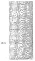
- FIG. 3 gives the distribution over time of a complete cycle of sub-images, of the number of ignitions determined by the table in FIG. 2.
- the distribution of the ignitions was chosen from among many others possible, and cannot be considered as a limiting characteristic of the invention.
- the minimum number of ignitions should preferably be done at the rate of approximately 50 times per second.
- the table in FIG. 3 shows that this condition is satisfied since, for the first level of illumination, two ignitions are provided at sub-images 1 and 33. This thus avoids any flickering.
- the ignition times are as far as possible, regularly distributed over time.
- the information read in the conversion table T is transmitted in series at the output S to the cascade of shift registers 13.
- the output of each stage of a register controls a flip-flop 12 which itself feeds a light-emitting diode 13.
- an order to load the flip-flops 12 is transmitted to all these flip-flops, via the conductor 15.
- the flip-flops load the information contained momentarily in all shift registers. Light emitting diodes stay on or off according to the values stored in the rockers during all the time of display of a sub-image. During this time, the shift registers receive the information from the next subimage.
- 64 sub-images have thus been displayed in a 25th of a second, the content of the memory M3 is modified and the system again elaborates a cycle of 64 sub-images.
Landscapes
- Engineering & Computer Science (AREA)
- Multimedia (AREA)
- Signal Processing (AREA)
- Physics & Mathematics (AREA)
- Computer Hardware Design (AREA)
- General Physics & Mathematics (AREA)
- Theoretical Computer Science (AREA)
- Control Of Indicators Other Than Cathode Ray Tubes (AREA)
- Medicines Containing Antibodies Or Antigens For Use As Internal Diagnostic Agents (AREA)
Applications Claiming Priority (2)
| Application Number | Priority Date | Filing Date | Title |
|---|---|---|---|
| FR8902799A FR2644001B1 (fr) | 1989-03-03 | 1989-03-03 | Systeme de visualisation d'images |
| FR8902799 | 1989-03-03 |
Publications (2)
| Publication Number | Publication Date |
|---|---|
| EP0391755A2 true EP0391755A2 (de) | 1990-10-10 |
| EP0391755A3 EP0391755A3 (de) | 1992-01-29 |
Family
ID=9379341
Family Applications (1)
| Application Number | Title | Priority Date | Filing Date |
|---|---|---|---|
| EP19900400570 Withdrawn EP0391755A3 (de) | 1989-03-03 | 1990-03-01 | Bildanzeigesystem |
Country Status (3)
| Country | Link |
|---|---|
| EP (1) | EP0391755A3 (de) |
| CA (1) | CA2011349A1 (de) |
| FR (1) | FR2644001B1 (de) |
Cited By (4)
| Publication number | Priority date | Publication date | Assignee | Title |
|---|---|---|---|---|
| DE4231302A1 (de) * | 1991-09-25 | 1993-04-29 | Toshiba Kawasaki Kk | Fluessigkristallanzeige-vorrichtung |
| US5436658A (en) * | 1991-11-20 | 1995-07-25 | Sony Corporation | Camera apparatus for forming a plurality of different kinds of pictures corresponding to different television standards and different aspect ratios |
| WO1998009433A1 (en) * | 1996-08-30 | 1998-03-05 | Ut Automotive Dearborn, Inc. | Method for controlling the brightness level of a screen display |
| EP3550550A1 (de) * | 2018-04-05 | 2019-10-09 | Commissariat à l'énergie atomique et aux énergies alternatives | Bildanzeigevorrichtung und -verfahren mit einer datenspeicherung in den pixeln |
Family Cites Families (3)
| Publication number | Priority date | Publication date | Assignee | Title |
|---|---|---|---|---|
| EP0193728B1 (de) * | 1985-03-08 | 1992-08-19 | Ascii Corporation | Anzeigesteuersystem |
| JPH0654963B2 (ja) * | 1986-01-24 | 1994-07-20 | 三菱電機株式会社 | フラツトマトリクスcrtの輝度調整方式 |
| IT1219550B (it) * | 1987-04-23 | 1990-05-18 | Seiko Instr Inc | Modulatore elettro-ottico,in particolare dispositivo a cristalli liquidi basato sull' effetto della birifrangenza a supertorsione |
-
1989
- 1989-03-03 FR FR8902799A patent/FR2644001B1/fr not_active Expired - Fee Related
-
1990
- 1990-03-01 EP EP19900400570 patent/EP0391755A3/de not_active Withdrawn
- 1990-03-02 CA CA 2011349 patent/CA2011349A1/fr not_active Abandoned
Cited By (6)
| Publication number | Priority date | Publication date | Assignee | Title |
|---|---|---|---|---|
| DE4231302A1 (de) * | 1991-09-25 | 1993-04-29 | Toshiba Kawasaki Kk | Fluessigkristallanzeige-vorrichtung |
| US5436658A (en) * | 1991-11-20 | 1995-07-25 | Sony Corporation | Camera apparatus for forming a plurality of different kinds of pictures corresponding to different television standards and different aspect ratios |
| WO1998009433A1 (en) * | 1996-08-30 | 1998-03-05 | Ut Automotive Dearborn, Inc. | Method for controlling the brightness level of a screen display |
| US6271813B1 (en) | 1996-08-30 | 2001-08-07 | Lear Automotive Dearborn, Inc. | Voltage control for adjusting the brightness of a screen display |
| EP3550550A1 (de) * | 2018-04-05 | 2019-10-09 | Commissariat à l'énergie atomique et aux énergies alternatives | Bildanzeigevorrichtung und -verfahren mit einer datenspeicherung in den pixeln |
| EP4418247A1 (de) * | 2018-04-05 | 2024-08-21 | Commissariat à l'énergie atomique et aux énergies alternatives | Bildanzeigevorrichtung und verfahren mit in pixeln hergestellter datenspeicherung |
Also Published As
| Publication number | Publication date |
|---|---|
| FR2644001A1 (fr) | 1990-09-07 |
| FR2644001B1 (fr) | 1992-12-18 |
| EP0391755A3 (de) | 1992-01-29 |
| CA2011349A1 (fr) | 1990-09-03 |
Similar Documents
| Publication | Publication Date | Title |
|---|---|---|
| FR2633426A1 (fr) | Procede et dispositif de commande de visualisation en couleur | |
| FR2604019A1 (fr) | Dispositif d'affichage video couleur pour systeme d'ordinateur, et procede de conversion de signaux video couleur a cet effet | |
| FR2554256A1 (fr) | Appareil et procede de regeneration d'un tampon de trames fonctionnant a grande vitesse | |
| JPS59501179A (ja) | 相互作用の色番地を持つビデオ画像のオ−バ−レ−システム | |
| CH618283A5 (de) | ||
| EP0233095B1 (de) | Digitaler Bildumsetzer zur Homogenisierung eines Bildes,erzeugt aus einer Koordinatentransformation. | |
| FR2618282A1 (fr) | Procedes et appareils d'emmagasinage de signaux video numeriques. | |
| FR2738944A1 (fr) | Affichage permettant de realiser un affichage a echelle de gris selon un procede par sous-trames, unite d'affichage et generateur de signal d'affichage correspondants | |
| FR3079957A1 (fr) | Dispositif et procede d'affichage d'images avec une memorisation de donnees realisee dans les pixels | |
| FR2644001A1 (fr) | Systeme de visualisation d'images | |
| EP0178219B1 (de) | Verfahren zur Verarbeitung von synthetischen Videobildern für Anzeige in Echtzeit und mit hoher Informationsdichte und dieses Verfahren verwendende Anordnung | |
| EP0306403A1 (de) | Flachbildschirmanzeigevorrichtung mit vom Benutzer gesteuerter Anzeige | |
| FR2762703A1 (fr) | Procede et dispositif d'adressage a code tournant pour ecrans a plasma | |
| EP0524842B1 (de) | Vorrichtung zur Fernsehbildwiedergabe in Echtzeit auf einem Anzeigebildschirm | |
| CN110706633B (zh) | 一种dmd高灰度级图像显示方法及装置 | |
| EP0472463B1 (de) | Verfahren zur Darstellung von Bildern auf einem Matrixbildschirm sowie System zur Durchführung dieses Verfahrens | |
| JPH11501415A (ja) | デジタル光変調器の多フレーム速度作動 | |
| FR2458863A1 (fr) | Terminal d'affichage video et procede d'affichage mixte graphique et alphanumerique | |
| FR2477745A1 (fr) | Dispositif d'affichage graphique en couleurs | |
| FR2637706A1 (fr) | Dispositif d'effacement rapide de l'ecran d'affichage d'un ordinateur, notamment pour la creation d'images animees | |
| FR2631474A1 (fr) | Circuit et procede pour commander la presentation d'une information de couleurs a un dispositif d'affichage d'un systeme informatique | |
| FR2579789A1 (fr) | Circuit controleur de signaux video de co uleur pour systeme de visualisation haute resolution et systeme de visualisation comportant un tel circuit | |
| EP0236177B1 (de) | Verfahren zur Optimierung der Speicherung von Videosignalen in einem digitalen Bildkonverter und digitaler Bildkonverter unter Verwendung eines solchen Verfahrens | |
| FR2836588A1 (fr) | Procede d'affichage numerique d'image et dispositif d'affichage numerique | |
| FR2665542A1 (fr) | Procede de mise en óoeuvre d'une memoire tampon permettant de produire un schema de declenchement et appareil de memorisation tampon associe. |
Legal Events
| Date | Code | Title | Description |
|---|---|---|---|
| PUAI | Public reference made under article 153(3) epc to a published international application that has entered the european phase |
Free format text: ORIGINAL CODE: 0009012 |
|
| AK | Designated contracting states |
Kind code of ref document: A2 Designated state(s): AT BE CH DE DK ES GB GR IT LI LU NL SE |
|
| PUAL | Search report despatched |
Free format text: ORIGINAL CODE: 0009013 |
|
| AK | Designated contracting states |
Kind code of ref document: A3 Designated state(s): AT BE CH DE DK ES GB GR IT LI LU NL SE |
|
| 17P | Request for examination filed |
Effective date: 19920720 |
|
| 17Q | First examination report despatched |
Effective date: 19940801 |
|
| STAA | Information on the status of an ep patent application or granted ep patent |
Free format text: STATUS: THE APPLICATION IS DEEMED TO BE WITHDRAWN |
|
| 18D | Application deemed to be withdrawn |
Effective date: 19941213 |