EP0391856A2 - Marteau pneumatique - Google Patents
Marteau pneumatique Download PDFInfo
- Publication number
- EP0391856A2 EP0391856A2 EP19900810267 EP90810267A EP0391856A2 EP 0391856 A2 EP0391856 A2 EP 0391856A2 EP 19900810267 EP19900810267 EP 19900810267 EP 90810267 A EP90810267 A EP 90810267A EP 0391856 A2 EP0391856 A2 EP 0391856A2
- Authority
- EP
- European Patent Office
- Prior art keywords
- housing
- handles
- hammer
- pusher
- handle
- Prior art date
- Legal status (The legal status is an assumption and is not a legal conclusion. Google has not performed a legal analysis and makes no representation as to the accuracy of the status listed.)
- Withdrawn
Links
- 230000005540 biological transmission Effects 0.000 claims abstract description 13
- 229910000831 Steel Inorganic materials 0.000 description 2
- 239000004033 plastic Substances 0.000 description 2
- 239000010959 steel Substances 0.000 description 2
- 230000015556 catabolic process Effects 0.000 description 1
- 238000013016 damping Methods 0.000 description 1
- 230000000994 depressogenic effect Effects 0.000 description 1
- 238000006073 displacement reaction Methods 0.000 description 1
- 238000010292 electrical insulation Methods 0.000 description 1
- 230000002349 favourable effect Effects 0.000 description 1
- 210000003205 muscle Anatomy 0.000 description 1
- 239000006223 plastic coating Substances 0.000 description 1
- 230000000750 progressive effect Effects 0.000 description 1
- 239000007787 solid Substances 0.000 description 1
Images



Classifications
-
- B—PERFORMING OPERATIONS; TRANSPORTING
- B25—HAND TOOLS; PORTABLE POWER-DRIVEN TOOLS; MANIPULATORS
- B25D—PERCUSSIVE TOOLS
- B25D17/00—Details of, or accessories for, portable power-driven percussive tools
- B25D17/04—Handles; Handle mountings
- B25D17/043—Handles resiliently mounted relative to the hammer housing
-
- B—PERFORMING OPERATIONS; TRANSPORTING
- B25—HAND TOOLS; PORTABLE POWER-DRIVEN TOOLS; MANIPULATORS
- B25D—PERCUSSIVE TOOLS
- B25D2250/00—General details of portable percussive tools; Components used in portable percussive tools
- B25D2250/371—Use of springs
- B25D2250/381—Leaf springs
Definitions
- a breakdown hammer according to the preamble of claim 1 is known from EP-B 0 115 241.
- This hammer has a housing and two protruding handles.
- the handles are hinged to the housing and loaded with springs upwards. They cross each other. With this measure, the vibrations acting on the operator during operation of the hammer can be reduced.
- the joints transmit the lower vibration frequencies practically undamped to the levers and thus to the operator's arms. In addition, the joints are exposed to strong vibration friction.
- the present invention has for its object to provide a hammer in which even low-frequency vibrations are effectively shielded from the handles. This object is achieved by the characterizing features of claim 1.
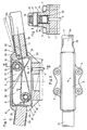
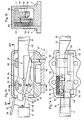
- a cylindrical pin 5 connected to a valve member, not shown, is displaceable parallel to the axis 2 and loaded upwards by a spring, not shown.
- two handles 11, 12 are attached to the free ends. Loop around the two slightly more than 180 ° bends 13, 14 of the spring 10 in the unloaded state shown with a little play each a plastic roller 15, 16, each of which is mounted on a hollow mandrel 17, 18 pressed into transverse bores of the casing 3.
- the mandrels 17, 18 have approximately the same distance from the axis 2 and are offset from one another in the axial direction.
- they rest against stops 19, 20 of the casing 3 with a prestress of approximately 30 N each.
- a pusher 22 designed as a double-armed lever is fastened so as to be pivotable about a pin 23 perpendicular to the axis 2.
- the first arm of the pusher 22 forms the pusher member 24 and extends above the handle 11. In the unactuated state, it is at a distance from the handle 11 (indicated by dash-dotted lines). In the actuated state shown in solid lines in FIG. 1, the pusher member 24 rests on the handle 11.
- the second arm of the handle 22 is formed by two folded, approximately triangular, mutually parallel, approximately gripping tabs 25.
- the end face of the tabs 25 facing away from the handle 11 forms an arcuate link 27 and has a center of curvature which approximately coincides with the pivot center 26 of the handle 11 when the handle 22 is actuated.
- the swivel center 26 is somewhat outside the casing 3, so that the handles 11, 12 swivel only slightly when deflected.
- the natural frequency given by the spring constant of the leaf spring 10 and the mass of the handles 11, 12 is substantially lower than the hammer's impact frequency. At a frequency of approximately 16 Hz, a natural frequency of the handles 11, 12 of approximately 7 Hz is expedient.
- the spring stiffness is expediently chosen such that the handles 11, 12 deflect about half of their maximum deflection with a normal contact force of about 60 N each.
- the handles 11, 12 are made relatively solid, for example made of steel with a plastic coating 28 for thermal and electrical insulation.
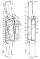
- two triangular sheets 31, 32 are each pivotably mounted on the mandrels 17, 18.
- the sheets 31, 32 serve on the one hand to protect against wear, on the other hand they transmit the movement of the push button 22 to the pin 5.
- a corner 33 of the sheets 31 lies against both the link 27 and an end edge of the sheets 32.
- the sheets 32 are connected to one another below by a web 34.
- the web 34 lies on the front end of the pin 5.
- the described design of the attachment of the handle and the valve actuation is very simple and can therefore be manufactured inexpensively. It enables one effective damping of the vibration transmission between housing 1 and handles 11, 12 in a wide frequency range, so that the operator is optimally protected against the joint-damaging vibrations.
- the power transmission when the handles are loaded transversely to the axis 2 takes place via a long base by lateral support of the leaf spring 10 on the sheets 31, 32 made of steel or plastic. As a result, wear is minimal. Because of the bends 13, 14 the pivot centers 26 are far from the handles 11, 12, these spring almost parallel to themselves, so that the pivoting movements of the handles 11, 12 are small during operation and these handles are relatively close to the housing 1 can be arranged.
- the casing 3 with the fully assembled leaf spring 10, the handles 11, 12 and the pusher mechanism 22, 31, 32 can be screwed onto the housing 1 as a finished structural unit 6. This makes it possible to unscrew the head of existing breakers with the unsprung handles and to replace them by the assembly 6 according to the invention without significant additional weight.
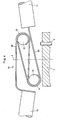
- FIG. 4 shows a variant of the embodiment according to FIGS. 1 to 3 in simplified form, with the pusher mechanism 22, 31, 32 and the casing 3, which are of the same design as in the embodiment according to FIGS. 1 to 3, being omitted are.
- the Z-shaped leaf spring 10 consists of two individual springs 38, 39, which each wrap around both rollers 15, 16. This variant has the advantage that the springs 38, 39 are somewhat softer than the one-piece spring 10 according to FIG. 1 with the same dimensioning.
- the leaf spring 10 is also formed by two individual springs 38, 39, which, however, are laterally offset from one another. Accordingly, the rollers 15, 16 are somewhat shorter than half the distance between the side walls 30.
- the mandrels 17, 18 are only attached to one of the side walls 30.
- the tab 25 of the handle 22 with the link 27 is only formed on one side on the handle 11.
- the transmission plates 31, 32 are arranged between the two individual springs 38, 39, and the web 34, which actuates the pin 5, is merely a local widening of the edge of the plate 32.
- the two mandrels 17, 18 are at the same height.
- the individual springs 38, 39 wrap around the rollers 15, 16 from above at an angle of slightly more than 180 ° and are in the installed state with their free ends adjacent to the associated handle on the housing 1. If the handles 11, 12 are pushed through, the contact point of the individual springs 38, 39 on the housing 1 shifts inwards. This results in a progressive spring characteristic. Wear plates can also be arranged between the individual springs 38, 39 and the walls 30.
- the two individual springs 38, 39 are in turn laterally offset from one another. Here, however, they are clamped to a lower part 43 of the assembly 6 by means of the screws 4 and blocks 42.
- the bends 13, 14 extend from this clamping point over a little more than 180 °. Due to these bends 14, the pivot center 26 of the handle 11 is in turn at a large distance from this handle, so that it pivots only slightly when it bounces.
- the link 27 of the second arm 25 of the pusher 22 presses here on a spring-loaded rod 44 mounted in the blocks 42, the other end of which is bevelled at 45 ° and acts on a likewise bevelled transmission pin 45.
- the pin 45 actuates the valve pin 5.
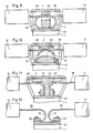
- variants of the embodiment according to FIGS. 7 and 8 are shown in simplified form, the handle with the transmission being omitted.
- the pusher and transmission can be designed, for example, analogously to the embodiment according to FIGS. 7 and 8, and in the variants according to FIGS. 11 and 12, for example analogously to the embodiment according to FIGS. 1 to 3.
- the individual springs 38, 39 are in turn laterally offset from one another, in the variants according to FIGS. 11 and 12, however, are arranged in a line. All variants in turn have the bends 13, 14 of at least 80 ° adjacent to the clamping points of the individual springs 38, 39. These bends 13, 14 shift the pivoting center of the handles 11, 12 away from the associated handles, so that the handles 11, 12 when Swivel the spring slightly.
- the handles 11, 12 are attached to two rigid levers 48, 49 which are laterally offset from one another.
- the levers 48, 49 are attached to rubber springs 50 at the end opposite the handles.
- the rubber springs 50 consist of a bracket 51, which is fastened to the housing 1 with one of the screws 4 and on which the one end face of a circular-cylindrical rubber block 52 is vulcanized.
- a circular disk 53 is vulcanized onto the other end face of the block 52.
- the levers 48, 49 are centered on the disks 53 with two pins 54 and screwed onto them with two screws 55.
- the rubber blocks 52 are subjected to scissors when the levers 48, 49 spring through.
- Each lever 48, 49 has a stop 56 overlapping the other lever at the top.
- the handles 11, 12 are also spring-loaded when the hammer is pulled, but to a lesser extent.
- the rubber springs 50 can be installed preloaded.
- the pusher 22 is again as double-armed lever.
- the second lever arm 25 acts here on the one arm 57 of a double-armed intermediate lever 58, which can be pivoted about a pin 59 seated in the lever 48.
- the free end of the other arm 60 of the lever 58 carries the link 27, which in turn is approximately concentric to the pivot center 26 of the lever 48 when the lever 22 is actuated.
- This pivot center 26 coincides approximately with the axis of the rubber block 52.
- the link 27 transfers the actuation of the trigger 22 to a transmission pin 61, which in turn actuates the valve pin 5.
- the handles 11, 12 are also attached to rigid levers 48, 49.
- the levers 48, 49 are pivotally mounted on bolts 65, 66 which are inserted in the side walls 30 of the casing 3.
- the bolts 65, 66 have approximately the same distance from the axis 2 of the hammer and are offset from one another in the axial direction.
- the lever 49 bears against a top wall 67 of the casing 3.
- the handle 12 is cranked slightly upward relative to the lever 49.
- the lever 48 covered by the lever 49 between the bolts 65, 66 in the axial projection lies against the lever 49 in the basic position.
- the handle 11 is slightly bent downward relative to the lever 49.
- Both levers 48, 49 have U-shaped cross sections. They are each biased into the basic position by an axially parallel spring 68. Between the legs of the U-shaped cross section of the lever 48, the pusher 22, again in the form of a two-armed lever, and the intermediate lever 58 with the pins 23, 59 are pivotably mounted. The free end of the arm 60 of the intermediate lever 58 acts on the valve pin 5 which penetrates an opening 69 in the lever 48 adjacent to the pin 65.
- the handles 11, 12 have the same swivel plane and the levers 48, 49 are mounted on the bolts 65, 66 over the full width of the casing 3.
- This asymmetrical solution does indeed result in a slight lateral displacement of the two handles 11, 12 with respect to the axis 2 of the hammer, as can be seen from the fully depressed position of the handles 11, 12 shown in broken lines.
- this slight shift is hardly noticed by the operator and is negligible in any case in view of the weighty advantages of the simple structure, the robust guidance of the levers 48, 49 and the reliable transmission of the trigger actuation to the valve pin 5.
- This assembly 6 can also replace heads of existing hammers with unsprung handles with little effort, so that these existing hammers can also be converted in a user-friendly manner.
- the embodiment according to FIGS. 19 and 20 corresponds to that according to FIGS. 1 to 3.
- the same reference numerals are used for analog parts, so that a detailed description is unnecessary.
- the leaf spring 10 is in the embodiment according to FIG. 19 and 20 divided into two individual springs 10 running parallel to one another. Their free ends are cast in the handles 11, 12.
- the two sheets 31 ', 32' are arranged in the space between these individual springs.
- the arcuate backdrop 27 ' is formed by an edge of the sheet 31 and is accordingly convex.
- the tab 25 of the handle 22 presses against the backdrop 27 '.
- the dash-dotted actuated state of the backdrop 27 ' is the center of curvature in turn adjacent the pivot center 26 of the handle 11.
- FIGS. 19 and 20 has the advantage over that according to FIGS. 1 to 3 that the friction of the valve actuation mechanism is lower.
Landscapes
- Engineering & Computer Science (AREA)
- Mechanical Engineering (AREA)
- Percussive Tools And Related Accessories (AREA)
- Mechanically-Actuated Valves (AREA)
- Percussion Or Vibration Massage (AREA)
Applications Claiming Priority (2)
| Application Number | Priority Date | Filing Date | Title |
|---|---|---|---|
| CH1320/89 | 1989-04-07 | ||
| CH132089 | 1989-04-07 |
Publications (2)
| Publication Number | Publication Date |
|---|---|
| EP0391856A2 true EP0391856A2 (fr) | 1990-10-10 |
| EP0391856A3 EP0391856A3 (fr) | 1992-07-08 |
Family
ID=4207683
Family Applications (1)
| Application Number | Title | Priority Date | Filing Date |
|---|---|---|---|
| EP19900810267 Withdrawn EP0391856A3 (fr) | 1989-04-07 | 1990-04-03 | Marteau pneumatique |
Country Status (2)
| Country | Link |
|---|---|
| EP (1) | EP0391856A3 (fr) |
| AU (1) | AU5307190A (fr) |
Cited By (6)
| Publication number | Priority date | Publication date | Assignee | Title |
|---|---|---|---|---|
| EP0537875A1 (fr) * | 1991-10-16 | 1993-04-21 | MANNESMANN Aktiengesellschaft | Outil à pression entraîné par un fluide |
| WO1994027789A1 (fr) * | 1993-05-26 | 1994-12-08 | Ingersoll-Rand Company | Outil a moteur pourvu d'une poignee amortissant les vibrations |
| FR2808719A1 (fr) * | 2000-05-15 | 2001-11-16 | Sullair Europ | Systeme de prehension d'un appareil de percussion notamment |
| EP1166972A3 (fr) * | 2000-06-27 | 2004-01-21 | Framatome Connectors International | Mécanisme de liaison pour gachette d'un outil |
| WO2013030380A1 (fr) * | 2011-09-02 | 2013-03-07 | Robert Bosch Gmbh | Dispositif poignée |
| US20220314412A1 (en) * | 2019-07-18 | 2022-10-06 | Hilti Aktiengesellschaft | Hand-Held Power Tool |
Family Cites Families (5)
| Publication number | Priority date | Publication date | Assignee | Title |
|---|---|---|---|---|
| GB242218A (en) * | 1924-10-29 | 1926-03-11 | Ingersoll Rand Co | Improvement in pneumatic hammer tool |
| DE1216808B (de) * | 1964-10-28 | 1966-05-12 | Wacker Hermann | Anordnung zur Daempfung der UEbertragung von Schlaegen, Stoessen oder Schwingungen bei der Bedienung eines Schlaege, Stoesse oder Schwingungen erzeugenden motorisch betriebenen Arbeitsgeraetes, z. B. Hammer oder Stampfer |
| FR2540774A1 (fr) * | 1983-02-14 | 1984-08-17 | Maco Meudon Sa | Dispositif de commande pour poignees articulees sur un outil de chantier |
| SE438280B (sv) * | 1983-04-22 | 1985-04-15 | Roland Andersson | Vibrationsdempande handtag |
| JPH0673826B2 (ja) * | 1988-05-27 | 1994-09-21 | 協和合金株式会社 | 防振ハンドル装置 |
-
1990
- 1990-04-03 EP EP19900810267 patent/EP0391856A3/fr not_active Withdrawn
- 1990-04-06 AU AU53071/90A patent/AU5307190A/en not_active Abandoned
Cited By (8)
| Publication number | Priority date | Publication date | Assignee | Title |
|---|---|---|---|---|
| EP0537875A1 (fr) * | 1991-10-16 | 1993-04-21 | MANNESMANN Aktiengesellschaft | Outil à pression entraîné par un fluide |
| WO1994027789A1 (fr) * | 1993-05-26 | 1994-12-08 | Ingersoll-Rand Company | Outil a moteur pourvu d'une poignee amortissant les vibrations |
| FR2808719A1 (fr) * | 2000-05-15 | 2001-11-16 | Sullair Europ | Systeme de prehension d'un appareil de percussion notamment |
| WO2001087546A1 (fr) * | 2000-05-15 | 2001-11-22 | Sullair Europe | Systeme de prehension d'un appareil de percussion |
| EP1166972A3 (fr) * | 2000-06-27 | 2004-01-21 | Framatome Connectors International | Mécanisme de liaison pour gachette d'un outil |
| WO2013030380A1 (fr) * | 2011-09-02 | 2013-03-07 | Robert Bosch Gmbh | Dispositif poignée |
| US20220314412A1 (en) * | 2019-07-18 | 2022-10-06 | Hilti Aktiengesellschaft | Hand-Held Power Tool |
| US12048993B2 (en) * | 2019-07-18 | 2024-07-30 | Hilti Aktiengesellschaft | Hand-held power tool |
Also Published As
| Publication number | Publication date |
|---|---|
| EP0391856A3 (fr) | 1992-07-08 |
| AU5307190A (en) | 1990-10-11 |
Similar Documents
| Publication | Publication Date | Title |
|---|---|---|
| EP0397294B1 (fr) | Mécanisme de commande pour un interrupteur à vide avec un ressort de contact | |
| DE19617657C2 (de) | Vorrichtung zum Führen einer absenkbaren Schale für eine Überkopf-Gepäckablage, insbesondere in einem Passagierflugzeug | |
| EP0382911B1 (fr) | Dispositif de commande d'un embrayage d'automobile | |
| DE102008021865A1 (de) | Vorrichtung zum Dämpfen von Torsionsschwingungen | |
| DE19907483C2 (de) | Beidseitig wirkende Verstellvorrichtung | |
| EP0077006B1 (fr) | Frein de ski | |
| DE2612160A1 (de) | Staubsaugermundstueck mit zwei alternativ verwendbaren werkzeugen | |
| CH664039A5 (de) | Einrichtung zur anpassung der wirkung eines elektromagneten an eine vom elektromagneten zu betaetigende komponente. | |
| EP0934686B1 (fr) | Dispositif pour maintenir une unite peripherique d'entree | |
| DE3422634A1 (de) | Container mit einer tragplatte und einem paar von endseitigen kopfteilen | |
| DE4119937C2 (de) | Betätigungsmechanismus | |
| EP0662371B1 (fr) | Poignée à amortissement des vibrations | |
| EP1912856A1 (fr) | Ensemble levier et unite de commande pour des vehicules guides par un guidon | |
| DE2502693C2 (de) | Vorrichtung zur Betätigung von Kupplungen oder Bremsen | |
| DE2746386C2 (fr) | ||
| DE2801254C2 (de) | Baumschere | |
| DE2140833C2 (de) | Kippscharnier für die Frontscheibe einer Theke | |
| WO1995029495A1 (fr) | Systeme de levier pour transmettre une force motrice | |
| EP0617637B1 (fr) | Frein pour skis | |
| DE2836652C2 (de) | Schnappriegelgetriebe einer zweiflügeligen Feuerschutztür | |
| DE2408661C3 (de) | Piezoelektrische Vorrichtung | |
| EP0003352A1 (fr) | Dispositif d'entraînement pour interrupteurs | |
| DE870525C (de) | Abstellvorrichtung fuer Weckeruhren | |
| CH645476A5 (en) | Device for the controllable blocking and releasing of a prestressable switching shaft of a load interruptor switch | |
| DE2851817A1 (de) | Niederspannungs-schutzschalter mit einer hauptklinke, einer zwischenklinke und einem sperrglied |
Legal Events
| Date | Code | Title | Description |
|---|---|---|---|
| PUAI | Public reference made under article 153(3) epc to a published international application that has entered the european phase |
Free format text: ORIGINAL CODE: 0009012 |
|
| AK | Designated contracting states |
Kind code of ref document: A2 Designated state(s): AT CH DE FR GB IT LI SE |
|
| RIN1 | Information on inventor provided before grant (corrected) |
Inventor name: STEINER, HEINZ |
|
| PUAL | Search report despatched |
Free format text: ORIGINAL CODE: 0009013 |
|
| AK | Designated contracting states |
Kind code of ref document: A3 Designated state(s): AT CH DE FR GB IT LI SE |
|
| STAA | Information on the status of an ep patent application or granted ep patent |
Free format text: STATUS: THE APPLICATION IS DEEMED TO BE WITHDRAWN |
|
| 18D | Application deemed to be withdrawn |
Effective date: 19930109 |