EP0392488A2 - Optisches Videoplattenspielgerät - Google Patents
Optisches Videoplattenspielgerät Download PDFInfo
- Publication number
- EP0392488A2 EP0392488A2 EP90106921A EP90106921A EP0392488A2 EP 0392488 A2 EP0392488 A2 EP 0392488A2 EP 90106921 A EP90106921 A EP 90106921A EP 90106921 A EP90106921 A EP 90106921A EP 0392488 A2 EP0392488 A2 EP 0392488A2
- Authority
- EP
- European Patent Office
- Prior art keywords
- pickup head
- time base
- synchronizing pulse
- photo pickup
- jump
- Prior art date
- Legal status (The legal status is an assumption and is not a legal conclusion. Google has not performed a legal analysis and makes no representation as to the accuracy of the status listed.)
- Granted
Links
Images


Classifications
-
- G—PHYSICS
- G11—INFORMATION STORAGE
- G11B—INFORMATION STORAGE BASED ON RELATIVE MOVEMENT BETWEEN RECORD CARRIER AND TRANSDUCER
- G11B7/00—Recording or reproducing by optical means, e.g. recording using a thermal beam of optical radiation by modifying optical properties or the physical structure, reproducing using an optical beam at lower power by sensing optical properties; Record carriers therefor
- G11B7/002—Recording, reproducing or erasing systems characterised by the shape or form of the carrier
- G11B7/0037—Recording, reproducing or erasing systems characterised by the shape or form of the carrier with discs
-
- G—PHYSICS
- G11—INFORMATION STORAGE
- G11B—INFORMATION STORAGE BASED ON RELATIVE MOVEMENT BETWEEN RECORD CARRIER AND TRANSDUCER
- G11B20/00—Signal processing not specific to the method of recording or reproducing; Circuits therefor
- G11B20/10—Digital recording or reproducing
- G11B20/18—Error detection or correction; Testing, e.g. of drop-outs
-
- G—PHYSICS
- G11—INFORMATION STORAGE
- G11B—INFORMATION STORAGE BASED ON RELATIVE MOVEMENT BETWEEN RECORD CARRIER AND TRANSDUCER
- G11B7/00—Recording or reproducing by optical means, e.g. recording using a thermal beam of optical radiation by modifying optical properties or the physical structure, reproducing using an optical beam at lower power by sensing optical properties; Record carriers therefor
- G11B7/08—Disposition or mounting of heads or light sources relatively to record carriers
- G11B7/085—Disposition or mounting of heads or light sources relatively to record carriers with provision for moving the light beam into, or out of, its operative position or across tracks, otherwise than during the transducing operation, e.g. for adjustment or preliminary positioning or track change or selection
- G11B7/08505—Methods for track change, selection or preliminary positioning by moving the head
- G11B7/08517—Methods for track change, selection or preliminary positioning by moving the head with tracking pull-in only
-
- H—ELECTRICITY
- H04—ELECTRIC COMMUNICATION TECHNIQUE
- H04N—PICTORIAL COMMUNICATION, e.g. TELEVISION
- H04N5/00—Details of television systems
- H04N5/76—Television signal recording
- H04N5/91—Television signal processing therefor
- H04N5/93—Regeneration of the television signal or of selected parts thereof
- H04N5/95—Time-base error compensation
- H04N5/953—Time-base error compensation by using an analogue memory, e.g. a CCD shift register, the delay of which is controlled by a voltage controlled oscillator
-
- H—ELECTRICITY
- H04—ELECTRIC COMMUNICATION TECHNIQUE
- H04N—PICTORIAL COMMUNICATION, e.g. TELEVISION
- H04N9/00—Details of colour television systems
- H04N9/79—Processing of colour television signals in connection with recording
- H04N9/80—Transformation of the television signal for recording, e.g. modulation, frequency changing; Inverse transformation for playback
- H04N9/82—Transformation of the television signal for recording, e.g. modulation, frequency changing; Inverse transformation for playback the individual colour picture signal components being recorded simultaneously only
- H04N9/85—Transformation of the television signal for recording, e.g. modulation, frequency changing; Inverse transformation for playback the individual colour picture signal components being recorded simultaneously only the recorded brightness signal occupying a frequency band totally overlapping the frequency band of the recorded chrominance signal, e.g. frequency interleaving
Definitions
- the present invention relates generally to video disc players and, more particularly, is directed to a video disc player and a method for reproducing a video disc in which a video signal is reproduced in a so-called scan reproduction mode.
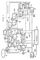
- a microcomputer 70 which controls the whole operation of this optical video disc player.
- an optical type video disc 10 on which there is recorded a signal, FM-modulated by a color composite video signal in the constant linear velocity (CLV) format.
- the optical video disc 10 is rotated by a spindle motor 51 and is servo-controlled by a spindle servo circuit 50 so that it is rotated in a constant linear velocity fashion.
- a photo pickup head (optical head) 21 for the disc 10 includes a laser light emitting element, a light receiving element for receiving a laser light emitted from the light emitting element, an objective lens, a tracking coil for moving an optical axis of the objective lens in the radial direction of the optical disc 10 and so on, though not shown.
- the photo pickup head 21 is moved in the radial direction of the optical disc 10 by a sled motor 44.
- a tracking servo circuit 30 wherein one portion of an output signal from the photo pickup head 21 is supplied to a detecting circuit 31 which generates a tracking error voltage Vt.
- This tracking error voltage Vt is supplied through an amplifier 32 to the tracking coil of the photo pickup head 21, whereby the object lens is servo-controlled in tracking.
- a sled servo circuit 40 in which the tracking error voltage Vt from the detecting circuit 31 is supplied to a low-pass filter 41, from which there is derived a DC component of the tracking error voltage Vt. This DC component is supplied through a switching circuit 42 and an amplifier 43 to the sled motor 44 to servo control the sled.
- the photo pickup head 21 is servo-controlled by the tracing servo circuit 30 and the sled servo circuit 40 so that the photo pickup head 21 correctly traces the tracks on the disc 10 to thereby produce a reproduced signal.
- This reproduced signal is supplied through a playback amplifier 22 and a limiter 23 to an FM demodulating circuit 24, in which it is demodulated to provide a color composite video signal Sc.
- the color composite video signal Sc is supplied to a time base corrector 25, in which a jitter component is removed therefrom.
- the signal Sc from the demodulating circuit 24 is supplied to a charge coupled device (CCD) 251, and the signal Sc from the CCD 251 is supplied to a synchronizing separating circuit 252, from which there is derived a horizontal synchronizing pulse PBH2.
- the horizontal synchronizing pulse PBH2 and a synchronizing pulse REFH are supplied to a phase comparing circuit.
- the synchronizing pulse REFH has a reference horizontal frequency and is derived from a master reference signal generating circuit 61.
- the phase comparing circuit 253 derives a phase-compared output of the pulses PBH2 and REFH which it supplies to a low-pass filter 254 which generates a time base error voltage TBCE whose level changes in response to the phase difference between the pulses PBH2 and REFH.
- the time base error voltage TBCE is supplied to a voltage controlled oscillator (VCO) 255 as a control signal, and an oscillation signal from the VCO 255 is supplied to the CCD 251 as a clock signal.
- VCO voltage controlled oscillator
- the pulse PBH2 becomes a signal having a constant phase synchronized with the reference pulse REFH so that the video signal Sc from the CCD 251 at that time becomes a signal whose jitter component is removed.
- This video signal Sc is supplied through a switching circuit 28 to an output terminal 29.
- a vertical synchronizing signal PBV is separated from the video signal Sc and this pulse PBV is supplied to the servo circuit 50.
- the generating circuit 61 derives a synchronizing pulse REFV of reference vertical frequency, and this synchronizing pulse REFV is supplied to the servo circuit 50, whereby the revolution of the motor 51 is controlled in such a manner that the pulse PBV is synchronized with the pulse REFV and a first spindle servo is performed.
- the video signal Sc from the demodulating circuit 24 is supplied to a synchronizing separating circuit 52, which derives a horizontal synchronizing pulse PBH1.
- This horizontal synchronizing pulse PBH1 is supplied to the servo circuit 50 along with the pulse REFH from the generating circuit 61 whereby the revolution of the motor 51 is controlled so that the pulse PBH1 is synchronized with the pulse REFH and a second spindle servo is performed.
- the spindle servo is performed such that the reproduced synchronizing pulses PBV and PBH1 are synchronized with the reference synchronizing pulses REFV and REFH.
- the operation of the video disc player in the normal playback mode is described so far.
- the objective lens When the photo pickup head 21 is moved to the control limit of the tracking servo, the objective lens performs a so-called track jump and again starts tracking the target track next to the jumped track.
- the tracking servo is turned OFF, and the track jump is forcibly performed.
- the correct video signal Sc can be obtained intermittently, whereby a reproduced picture in the fast-forward or fast-rewind mode can be obtained by utilizing the correct video signal reproduced.
- the above- mentioned operation mode will be referred to as the "scan mode” or "scan playback" mode.
- the switching circuit 42 In the scan playback mode, under the control of the microcomputer 70, the switching circuit 42 is changed to the opposite state to that shown Fig. 1, namely, the switching circuit 42 is connected to a fixed contact SCN, and also the signal generating circuit 61 generates a sled pulse SLDP at, for example, every 4 field periods.
- This sled pulse SLDP is supplied through the switching circuit 42 and the amplifier 43 to the motor 44, causing the photo pickup head 21 to be moved toward the inner peripheral or outer peripheral direction of optical video disc 10 at a speed higher than that of the normal playback mode.
- a track jump pulse TJMP from the microcomputer 70 is supplied to the detecting circuit 31, allowing the objective lens within the photo pickup head 21 to perform the track jump.
- the correct video signal Sc is obtained so that, similarly to the normal playback mode, the correct video signal Sc is obtained at the output terminal 29.
- the correct video signal Sc is not obtained and only a noise signal is obtained so that the switching circuit 28 is connected to a fixed contact DUM by the microcomputer 70.
- horizontal and vertical reference synchronizing pulses REFH and REFV, respectively, from the signal generating circuit 61 are supplied to a dummy signal generating circuit 62 which generates a pseudo-video signal Sq which is reproduced as, for example, a gray picture.
- the signal Sq is supplied through the switch circuit 28 to the output terminal 29.
- a reproduced picture based on the correct video signal Sc and the gray picture based on the pseudo-video signal Sq are alternately displayed, whereby the user can temporarily check a picture between the jumps in the fast-forward or fast-rewind mode.
- the reference synchronizing pulse REFH and the reproduced synchronizing pulses PBH1 and PBH2 are substantially the same in phase. Therefore, as shown in the period just before the time point t1 of Fig. 2E, the time base error voltage TBCE slightly fluctuates up and down around a central value Ec in response to the jitter component.
- the pulses PBH1 and PBH2 become noise components during this period.
- the jitter component is compensated for by the CCD 251 so that the pulse PBH2 is delayed from the pulse PBH1 by a delay time of substantially one horizontal period (1H), which fact can be neglected in this description.
- the low-pass filter 254 is controlled by a control signal HOLD from the microcomputer 70, whereby the error voltage TBCE is held at a central value Ec from the time point t1.
- the pulses PBH1 and PBH2 are obtained at the next time point t3.
- the time point t3 at which the pulse PBH1 is obtained is random with respect to time point at which the pulse REFH is obtained so that, as shown in Figs. 2A and 2B, they are not generally coincident with each other. If the time points of the two pulses PBH1 and REFH are not coincident with each other, then the TBC 25 must compensate for the jitter component while inceimpulsly absorbing the phase difference between the two pulses PBH1 and REFH. Therefore, the TBC 25 needs a wide compensation range.
- the microcomputer 70 supplies a control signal HRES to the generating circuit 61 to reset the pulse REFH at the time point t3 as shown in Fig. 2D and make the pulse REFH the same in phase as that of the pulse PBH1. Accordingly, the pulse REFH is generated at each horizontal period as described hereinbefore. Further, the holding state of the TBC 25 is released from the time point t3 by the hold signal HOLD.
- the above-mentioned correct video signal Sc is obtained from the time point t3 to the next track jump.
- the relative velocities of the pickup head to the disc track at the track jump point and at the track after the track jump are different.
- the time point t3 is just behind the track jump so that the response of the spindle servo circuit 50 cannot follow the track jump.
- the revolution speed of the optical video disc 10 is slower than the revolution speed needed by the track next to the jumped track and the revolution speed of the optical video disc 10 reaches the necessary revolution speed as the time passes.
- the cycle of the synchronizing pulse PBH1 is longer than the reference value just immediately after the time point t3 and reaches a reference value as the time passes.
- the TBC 25 compensates for the video signal Sc having the pulse PBH1 such that the cycle of the pulse PBH2 equals the reference value from the time point t3 so that the phase relationship among the pulses PBH1, PBH2 and REFH exceeds the compensation range of the TBC 25.
- the error voltage TBCE is fixed to a maximum value Eu or minimum value Ed as shown in the period succeeding to a time point t4 of Fig. 2E with the result that the TBC 25 cannot carry out the correct operation.
- a correct reproduced picture cannot be displayed.
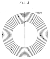
- the scan reprcduction is carried out as described above, if the optical video disc 10 is recorded according to the CLV format, the angular position at which the vertical synchronizing pulse PBV is recorded is slightly displaced from track to track as shown in Fig. 3 and a scan reproduced picture in which the synchronization is disturbed is obtained.
- N 2 ⁇ (R+P(N-1)) (m) (i).
- Video signals of two fields are recorded in the innermost peripheral track of the video disc according to the CLV format and one track length is fixed as ⁇ R so that the number F of the fields involved in the Nth track is expressed by the following equation (ii)
- the value k in the equation (i) represents the amount of how much the angular position at which the vertical synchronizing signal is recorded is changed when one track jump is carried out. That is, the value k indicates the amount in which the phase of the reproduced vertical synchronizing signal is changed.
- Fig. 4A shows the condition near a track portion where two video fields are recorded in one track, wherein vertical synchronizing pulses Vsync are aligned substantially in the radial direction of the disc.
- Fig. 4B shows the condition near a track portion in which three video signals are recorded in one track, wherein although the vertical synchronizing pulses Vsync are aligned substantially in the radial direction of the disc similarly to Fig. 4A, the phase of the reproduced vertical synchronizing pulses Vsync deviates by several 10s of percents from the phase of a reference vertical synchronizing pulse of the apparatus.
- the spindle servo is applied so that the phase of the vertical synchronizing pulse in the recorded signal deviates considerably from the phase of the reference vertical synchronizing pulse. Therefore, in the scan mode, the photo pickup head can not be pulled in a servo controllable range of ⁇ 3% by the servo control. If the photo pickup head is jumped into the track of this area, then a picture cannot be immediately reproduced and so, this area is referred to as a dead zone track area.
- Fig. 4C illustrates the condition near a track portion where 2.7 video fields are recorded in one track.
- the recorded positions of the vertical synchronizing pulses fluctuate around the recorded positions of the reference vertical synchronizing pulse. If the track shifting is carried out for at least 10 or more tracks near this track position, then at least the vertical synchronizing pulse of a certain track fails within a pull-in range of the servo control.
- the area in which the phase change of the vertical synchronizing pulse after the track jump is small and in which the phase of the reproduced vertical synchronizing pulse after a track jump of 10 or more tracks cannot match the phase of the reference vertical synchronizing pulse is referred to as a "dead zone track area.”
- the high speed scanning method comprising the steps of: carrying out a first jump by the photo pickup head of a relatively large number of tracks of the video disc in its radial direction; keeping in a standby mode for a predetermined time period after the first track jump by the photo pickup head which is necessary for the spindle servo to be stabilized; carrying out a second jump by the photo pickup head after the standby mode; holding the error voltage of the time base
- a second aspect of the present invention is a method for reproducing a constant linear velocity format recorded video signal from a video disc in a high-speed scan reproduction mode by carrying out track jumps using a video disc player of the type having a photo pickup head for reproducing a video signal from the video disc, a tracking servo circuit for servo-controlling the photo pickup head in tracking, a spindle servo circuit for controlling the linear velocity of the video disc to be constant, a time base corrector for generating an error correction signal and correcting a time base of the video signal reproduced, means for generating a reference horizontal synchronizing pulse for the time base of the time base corrector; and means for generating a reference vertical synchronizing pulse; wherein the method comprises the steps of: carrying out a first relatively large jump by the photo pickup head of tracks of the video disc in its radial direction; holding in a standby mode for a predetermined time period after the above-described jump by the photo pickup head to allow for the spindle servo to be stabilized;
- a third aspect of the present invention in a method for reproducing a constant linear velocity format recorded video signal from a video disc in a high-speed scan reproduction mode by carrying out track jumps using a video disc player of the type having a photo pickup head for reproducing a video signal from the video disc, a tracking servo circuit for servo-controlling the photo pickup head in tracking, a spindle servo circuit for controlling the linear velocity of the video disc to be constant, a time base corrector for generating an error correction signal and correcting a time base of the video signal reproduced, means for generating a reference horizontal synchronizing pulse for the time base of the time base corrector; and means for generating a reference vertical synchronizing pulse; wherein the method comprises the steps of: carrying out a first jump by the photo pickup head of a relatively large number of tracks of the video disc in its radial direction; keeping the video disc player in a standby mode for a predetermined time period after the first track jump by the photo pickup head; carrying out a second jump by
- a video disc player for reproducing a video disc recorded according to a constant linear velocity format
- the video disc player comprises: a photo pickup head for reproducing a video signal from the video disc; a tracking servo circuit for servo-controlling the photo pickup head in tracking; a spindle servo circuit for controlling the linear velocity of the video disc to be constant; a time base corrector for generating an error correction signal and correcting a time base of the video signal reproduced; means for generating a reference horizontal synchronizing pulse for the time base of the time base corrector; and means for generating a reference vertical synchronizing pulse; and scan reproduction means for reproducing the recorded video signals from the disc at high speed by carrying out track jumps and including: a circuit for carrying out a first jump by the photo pickup head of a relatively large number of tracks in the radial direction of the video disc; a circuit for causing the scan reproduction means to carry out a standby mode for a predetermined time period after the first track jump by the photo
- a slicer circuit 26 responds to a command signal issued from the microcomputer 70 to remove the vertical synchronizing pulse PBV from the video signal Sc of the TBC 25 on the basis of the reproduced vertical synchronizing pulse PBV derived from the synchronizing separating circuit 252 in the TBC 25 so that the pedestal level of the output video signal is changed, for example, to a black level.
- a synchronizing signal adding circuit 27 When supplied with a command signal from the microcomputer 70, the synchronizing signal adding circuit 27 adds the reference vertical synchronizing pulse REFV to the video signal Sc from the slicer circuit 26.
- the reproduced vertical synchronizing pulse PBV from the TBC 25 is supplied to the microcomputer 70, and the servo circuit 50 derives a signal SPLK which indicates the locked condition of the spindle servo.
- This signal SPLK is supplied to the microcomputer 70.
- the video signal Sc is supplied to a decoder 53, from which there is derived a time code TMC. This time code TMC is supplied to the microcomputer 70.
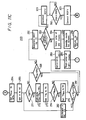
- the microcomputer 70 is provided with a routine 100 which is represented, for example, in Fig. 8. In the scan reproduction mode, this routine 100 of Fig. 8 is executed by the microcomputer 70.
- Figs. 9A to 9D illustrate the case where a scan reproduction in the fast rewind direction is carried out on a track about one minute after the reproduction of the innermost peripheral track is started. More specifically, as shown in Fig. 9A, the pseudo video signal Sq is generated at a time t11, whereby the reproduced picture is muted and becomes gray. Also, as shown in Fig. 9B, a track jump pulse TJMP is generated at the time point t11 to thereby carry out a track jump of, for example, 200 tracks.
- the hold signal HOLD goes to high "H" in level during a period of from t11 to t12
- the error voltage TBCE of the TBC circuit 25 is held at the central value Ec during a period of from t11 to t12.
- the reference pulse REFH is reset by the signal HRES from the microcomputer 70 so that the phase thereof is made the same as that of the reproduced pulse PBH2.
- the microcomputer 70 is placed in the standby mode during a period of 30 milliseconds from the time point t12 to t13, and at the time point t13, a track jump of one track is carried out on the basis of the track jump pulse TJMP from the microcomputer 70. Also in this track jump of one track, the error voltage TBCE of the TBC circuit 25 is held and the reference pulse REFH is reset. Owing to the holding and resetting, the TBC circuit 25 is stabilized.
- an additional or fine track jump is performed on the basis of the track jump pulse TJMP at a time point t14.
- the number of tracks jumped by this fine track jump falls within a range of 0 to 20 tracks, and by this fine track jump, the reproduced synchronizing pulse PBV is synchronized with the reference synchronizing pulse REFV.
- the muting of the reproduced picture by the pseudo video signal Sq is released at a time point t15 and hence, the reproduced video signal Sc is produced.
- a track jump of 200 tracks and a track jump of one track are carried out at time points t16 and t17, respectively, but the fine track jump is not carried out.
- Figs. 10A to 10D illustrate a case in which a scan reproduction in the fast rewind mode is performed on the track about three minutes after the reproduction of the innermost peripheral track is started.
- a track jump is carried out similarly to Figs. 9A and 9D, whereas in the second half portion, when a track jump of 200 tracks is performed at a time point t21, the photo pickup head 21 enters the dead zone so that track jumps of one track at time points t22, t24 and t26 and fine track jumps at time points t23, t25 and t27 are alternately carried out.
- the video signal Sc is fed to the output terminal 29.
- the above-described track jump process is the same as that described in our above-identified co-pending U.S. Patent Application.
- step 101 when a scan reproduction fast forward or fast rewind key 71 (see Fig. 7) is depressed, the processing of the microcomputer 70 begins with step 101 in the routine 100.
- the initial value of the counter TFWC corresponds with the field period number from a certain track jump to the next track jump
- the initial value of the counter SFWC corresponds with the field period number wherein the pseudo video signal Sq is fed to the output terminal 29 in one track jump.
- the values, however, are standard values and these value are not necessarily satisfied on the picture screen.
- step 103 a dead zone decision counter NGCT made by the software is reset to [0].
- step 111 the switching circuit 42 is connected to the fixed contact SCN to permit the pulse SLDP to be fed to the sled motor 44 to start the scan.
- step 112 the vertical synchronizing pulse PBV is removed by the slicer circuit 26 and the vertical synchronizing pulse REFV is added by the adding circuit 27 so that thereafter the vertical synchronizing pulse of the video signal Sc is taken as the pulse REFV.
- the pulse REFV added to the output video signal Sc is located at the time position of the original pulse PBV.
- the counter TFWC corresponds with the field period number for a certain track jump to the next track jump
- the counter SFWC corresponds with the field period number wherein the pseudo video signal Sq is generated in one track jump. Therefore, the value RVWT corresponds with the field period number of the video signal Sc normally reproduced at every track jump.
- step 114 the reference vertical synchronizing pulse REFV is counted by the number of the value RVWT calculated in step 113. That is, the microcomputer 70 is placed in a standby mode during the RVWT field period. Accordingly, in step 114, during the RVWT field period, the normal video signal Sc is fed to the output terminal 29.
- step 115 the switching circuit 28 is connected to the fixed contact DUM so that the pseudo video signal Sq is fed to the output terminal 29 from the time point of the step 115.
- the reference synchronizing pulse REFV is employed as the standard of the vertical synchronization, whereby the vertical synchronization on the picture screen can be prevented from being disturbed throughout the above-mentioned processings.
- a track jump of, for example, 200 tracks is performed on the basis of the pulse TJMP.
- the error voltage TBCE of the TBC 25 is held at the central value Ec and the pulse REFH is reset by the signal HRES supplied from the microcomputer 70 after the track jump so that the reference pulse has the same phase as that of the reproduced pulse PBH2.
- step 117 during a period in which the synchronization disturbance produced in the spindle servo circuit 50 by the track jump in step 116 is stabilized, the microcomputer 70 is placed in a standby mode during a period of, for example, 30 milliseconds and the processing of the microcomputer proceeds to an additional or fine routine 200.
- the video signal Sc becomes synchronized with the reference synchronizing pulse REFV.
- the switching circuit 28 is connected to the fixed contract NR to thereby allow the video signal Sc to be supplied to the output terminal 29. Then, the processing of the microcomputer 70 returns to step 111 via a line OK1. Accordingly, in that case, the scan playback is continued.
- the video signal Sc is synchronized with the reference synchronizing pulse REFV. If the scan playback key is released, the switching circuit 28 is connected to the fixed contact NR to permit the above-described video signal Sc to be fed to the output terminal 29. Also, the removal of the pulse PVB in the slicer circuit 26 and the addition of the pulse REFV in the adding circuit 27 are inhibited and then the processing of the microcomputer 70 proceeds to step 121 via a line OK2 to end the routine 100. Accordingly, in that case, the scan playback is ended and the video disc player is set in the normal playback mode.
- step 200 when the photo pickup head 21 in the scan reproduction mode enters the dead zone, the processing of the microcomputer 70 stays at the routine 200 via a line NG1. Further, in the routine 200, when the locking of the spindle servo circuit 50 is extraordinarily slow, the processing of the microcomputer 70 returns to step 116 through a line NG2.
- the routine 200 is constructed and executed as shown in Figs. 11A and 11B.
- the routine 200 begins with step 201, and in the next decision step 202, it is determined whether or not the reproduced synchronizing pulse PBV exists.
- the step 202 is repeated until the reproduced synchronizing pulse PBV is obtained.
- the processing of the microcomputer 70 proceeds to the next step 203.
- step 203 a phase difference TH2 between the reference vertical pulse REFV and the reproduced vertical pulse PBV is calculated. In that case, when the phase of the target pulse PBV is the same as that of the pulse REFV, as shown in Figs. 12A and 12B, the phase difference TH2 is equal to 0%.
- phase difference TH2 is equal to 50%.
- the phase difference TH2 is equal to 100%. This relationship applies for other phase differences as well.
- step 204 a track jump of one track is carried out on the basis of the pulse TJMP.
- the error voltage TBCE is held by the signal HOLD, and at the completion of the track jump, the phase of the reference horizontal synchronizing pulse REFH is reset to that of the reproduced pulse PBH2 by the reset command signal HRES.
- step 205 The processing of the microcomputer 70 proceeds to the next decision step 205. It is again determined in step 205 whether or not the reproduced pulse PBV exists. The step 205 is repeated until the next reproduced pulse PBV is obtained. When the pulse PBV is obtained as represented by a YES, the processing of the microcomputer 70 proceeds to the next step 206. In step 206, a phase difference TH3 between the pulse REFV and the pulse PBV is calculated. In the next decision step 211, it is determined whether, for example, the following equation (i) is satisfied or not.
- step 212 a track jump counter TJCT in the software is reset to "0".
- step 212 the processing of the microcomputer 70 proceeds from step 212 to step 213 where the reference vertical synchronizing counter RVCT made by the software is reset to "0", and the processing of the microcomputer 70 proceeds to the next decision step 214. It is determined in decision step 214 whether or not the pulse REFV exists. The interrogation in step 214 is repeated until the pulse REFV is obtained. If it is determined that the pulse REFV exists as represented by a YES at step 214, then the processing of the microcomputer 70 proceeds to decision step 221 where it is determined whether or not the spindle servo is locked by the signal SPLK.
- step 221 If the spindle servo is locked as represented by a YES at step 221, then the processing of the microcomputer 70 proceeds from step 221 to the next decision step 222 where it is again determined whether or not the pulse REFV exists. The interrogation in step 222 is repeated until the pulse REFV is obtained. If the pulse REFV is obtained as represented by a YES at step 222, then the processing of the microcomputer 70 proceeds from step 222 to step 223. In step 223, the switching circuit 28 is connected to the fixed contact NR. Therefore, from the time point of this step 223, the signal Sc, scan-reproduced, is fed to the output terminal 29, whereby a picture in the scan playback mode is displayed.
- a track jump of one track is carried out at step 204.
- the pseudo video signal Sq is generated to mute the display screen, and during the period between a certain track jump and the next track jump, the reproduced video signal Sc is generated over the RVWT field period in which the normal reproduction is made possible at step 114. In this way the scan playback is performed.
- the adding circuit 27 derives the reproduced video signal Sc, the phase difference TH3 between the reference vertical synchronizing pulse REFV and the vertical synchronizing pulse PBV of the signal Sc falls within ⁇ 3% (in this case, however, the vertical pulse PBV of the signal Sc is removed at step 112 and the pulse REFV is added), and synchronization can be prevented from being disturbed.
- the error voltage TBCE of the TBC circuit 25 is held at the central value Ec and the reproduced horizontal synchronizing pulse REFH is reset so that the TBC 25 is operated correctly during the period in which the signal Sc is reproduced.
- step 241 the removal of the vertical synchronizing pulse PBV of the video signal Sc and the addition of the vertical synchronizing pulse REFV by the slicer circuit 26 and the adding circuit 27 are inhibited. Then, the processing of the microcomputer 70 proceeds to the next step 242, whereat the switching circuit 42 is connected to the fixed contact NR to interrupt the high speed movement of the photo pickup head 21 and to effect the normal sled servo. Thereafter, the routine 200 ends with the next step 243, and the processing of the microcomputer 70 returns to the line OK2. Accordingly, if the depression of the scan playback key 71 is released in the scan playback mode, the scan playback is ended.
- step 221 the processing of the microcomputer 70 proceeds from step 221 to step 251.
- step 251 the counter RVCT is incremented by [1] and the processing of the microcomputer 70 proceeds to the next decision step 252 where it is determined whether or not the condition of RVCT ⁇ TFWC is established. If RVCT ⁇ TFWC, the processing of the microcomputer 70 returns from step 252 to step 214.
- the counter RVCT is incremented at every reference pulse REFV and for so long as the condition of RVCT ⁇ TFWC is established, the steps 214, 221, 251 and 252 are repeated to until the spindle servo of the spindle servo circuit 50 is locked. If the spindle servo is locked, the processing of the microcomputer 70 proceeds from step 221 to step 222 and the processing of the microcomputer 70 proceeds to step 233 or 243.
- step 252 the processing of the microcomputer 70 proceeds from step 252 to step 253 whereat the routine 200 is ended and the processing of the microcomputer 70 returns to step 116 via the line NG2.
- the value TH2 is the phase difference of the reproduced pulse PBV relative to the reference pulse REFV of one track jump before and which is calculated at step 203.
- the value TH3 is similar to the phase difference of one track after and which is calculated at step 206, whereby the value TH1 indicates the amount by which the phase of the reproduced pulse PBV is changed by the one track jump.
- step 264 in Fig. 11C
- a value TH min is set to 50%.
- the processing of the microcomputer 70 proceeds to step 265, whereat a fine track jump counter D made by the software, i.e., a counter for indicating the number of tracks jumped by the fine track jump, is set to [4].
- the processing of the microcomputer 70 proceeds to the decision step 271. lt is determined in step 271 whether or not the counter n is less that a predetermined value, e.g., if n ⁇ 22.
- the value TH n indicates a phase difference between. the reproduced pulse PBV and the reference pulse REFV when a track jump of (n-3) is performed.
- the value TH n exceeds 100%, a value, which results from subtracting 100% from that value, becomes the value TH n .
- an absolute value of the value TH n is set to a value TX, and the processing of the microcomputer 70 proceeds to the next decision step 274. It is determined at step 274 whether the value TX is larger than or smaller than the value TH min or vice versa. If TV ⁇ TH min , then the processing of the microcomputer 70 proceeds to step 275, whereat the value TH min is set to the value TX, and the processing of the microcomputer 70 proceeds to the next decision step 281. It is determined in step 281 whether or not TX ⁇ TH min is established. If TX ⁇ TH min at step 274, then the processing of the microcomputer 70 proceeds directly to decision step 281.
- step 281 it is determined whether or not the following condition (ii) is established: 3% ⁇ TH n ⁇ 97% (ii) If the above condition (ii) is established, then the processing of the microcomputer 70 proceeds from step 281 to step 282, wherein the counter n is incremented by [1] and the, the processing of the microcomputer returns to step 271.
- step 281 the processing of the microcomputer 70 proceeds from step 281 to step 283, whereat the value (n-3) is set in the counter TJCT.
- the error voltage TBCE of the TBC 25 is held by the signal HOLD, and at the completion of the track jump, the phase of the pulse REFH is set in the phase of the pulse PRB2 by the signal HRES.
- step 213 the processing of the microcomputer 70 proceeds to step 213, accordingly, the routine 200 is ended through any one of the steps 233, 243, and 253.
- step 271 determines whether or not TH min ⁇ 6% is established. If TH min ⁇ 6%, then the processing of the microcomputer 70 proceeds from step 291 to step 283.
- step 292 the counter NGCT is incremented by [1], and the processing of the microcomputer 70 proceeds to the next decision step 293 where it is determined whether or not the present track position falls within the position of three minutes of the time code of the optical video disc 10 and it is also determined whether or not an inequality of NGCT ⁇ 4 is established.
- the positions of the vertical synchronizing pulses PBV on the optical video disc 10 are substantially arranged in the radius direction of the optical video disc 10 like the CAV format. Accordingly, even if a track jump is carried out, the phase of the vertical synchronizing pulse PBV is not changed substantially. Further, when the routine 200 is repeated through the lines NG1 and NG2, the number of the repetitions is counted by the counter NGCT in the step 292.
- step 293 the time code and the counter NGCT are checked at step 293. If the above items are not established, then it is regarded that a relationship between the photo pickup head 21 and the track position lies in the dead zone, and the processing of the microcomputer 70 proceeds from step 293 to step 294.
- step 294 a forced sled feed pulse from the microcomputer 70 is supplied to the amplifier 43 to perform a fine sled feeding in addition to the sled feeding done by the sled pulse SLDP (the feed of the photo pickup head 21).
- a track jump of, for example, 200 tracks is carried out by the pulse TJMP.
- step 295 the microcomputer 70 is placed in a standby mode during a period of 12 milliseconds in order to stabilize the tracking.
- the error voltage TBCE is held by the signal HOLD, and at the completion of the step 295, the phase of the pulse REFH is reset to that of the pulse PBH2 by the signal HRES.
- step 295 the processing of the microcomputer 70 proceeds to step 296 and then the routine 200 is ended. Thereafter, the routine 200 is again executed through the line NG1. Accordingly, in the case of a dead zone, the routine 200 is repeated.
- step 293 If it is determined that the conditions for the time code and the counter NGCT are established as represented by a YES at step 293, then the processing of the microcomputer 70 proceeds from step 293 to step 301.
- step 301 the microcomputer 70 controls the signal generating circuit 61 so that the frequency of the reference pulse REFV is increased by, for example, 2.5%.
- step 302 the phase difference between the reproduced pulse PBV and the reference pulse REFV is checked. If such a phase difference exceeds, for example, ⁇ 3%, the step 302 is repeated.
- step 302 If the phase difference between the pulse PBV and the pulse REFV falls within ⁇ 3%, this is identified at step 302, and the processing of the microcomputer 70 proceeds from step 302 to step 303 where the frequency of the reference pulse REFV is converted to the correct vertical frequency, and then the processing of the microcomputer 70 proceeds to step 223. Thereafter, the routine 200 is ended at either of the steps 233 or 243.
- the error voltage TBCE of the TBC 25 can be prevented from being fixed to the maximum value Eu or to the minimum value Ed and the TBC 25 operates normally.
- the vertical synchronization of the reproduced picture of the original video signal Sc can be prevented from being disturbed and also the upper half portion and the lower half portion of the picture can be prevented from being displayed in a reversed positional relationship.
- the ratio of the gray picture based on the pseudo video signal Sq can be reduced to thereby increase the ratio of the reproduced picture based on the video signal Sc. This, it is possible to more positively determine the content and screen position of the scan-reproduced picture.
- the item VII is executed, even through the optical video disc 10 of the CLV format is placed in the state of the CAV (constant angular velocity) format in a range where the time code lies within a range of 0 to 3 minutes, the gray picture based on the pseudo video signal Sq can be prevented from being continued for very long. Thus, it is possible to obtain the reproduced picture based on the reproduced video signal Sc nearly immediately.
Landscapes
- Engineering & Computer Science (AREA)
- Signal Processing (AREA)
- Multimedia (AREA)
- Moving Of The Head For Recording And Reproducing By Optical Means (AREA)
- Optical Recording Or Reproduction (AREA)
- Signal Processing Not Specific To The Method Of Recording And Reproducing (AREA)
- Television Signal Processing For Recording (AREA)
Applications Claiming Priority (2)
| Application Number | Priority Date | Filing Date | Title |
|---|---|---|---|
| JP93383/89 | 1989-04-13 | ||
| JP1093383A JP2751363B2 (ja) | 1989-04-13 | 1989-04-13 | ビデオディスクプレーヤ |
Publications (3)
| Publication Number | Publication Date |
|---|---|
| EP0392488A2 true EP0392488A2 (de) | 1990-10-17 |
| EP0392488A3 EP0392488A3 (de) | 1993-03-03 |
| EP0392488B1 EP0392488B1 (de) | 1995-12-06 |
Family
ID=14080788
Family Applications (1)
| Application Number | Title | Priority Date | Filing Date |
|---|---|---|---|
| EP90106921A Expired - Lifetime EP0392488B1 (de) | 1989-04-13 | 1990-04-11 | Optisches Videoplattenspielgerät |
Country Status (4)
| Country | Link |
|---|---|
| US (1) | US5159488A (de) |
| EP (1) | EP0392488B1 (de) |
| JP (1) | JP2751363B2 (de) |
| DE (1) | DE69023946T2 (de) |
Cited By (1)
| Publication number | Priority date | Publication date | Assignee | Title |
|---|---|---|---|---|
| DE19528720A1 (de) * | 1994-08-08 | 1996-02-15 | Hitachi Ltd | Plattenwiedergabegerät |
Families Citing this family (1)
| Publication number | Priority date | Publication date | Assignee | Title |
|---|---|---|---|---|
| JPH07115619A (ja) * | 1993-10-18 | 1995-05-02 | Sony Corp | ビデオ信号再生装置 |
Family Cites Families (19)
| Publication number | Priority date | Publication date | Assignee | Title |
|---|---|---|---|---|
| JPS57148975U (de) * | 1981-03-12 | 1982-09-18 | ||
| JPS5898881A (ja) * | 1981-12-08 | 1983-06-11 | Pioneer Video Corp | 情報記録デイスク再生装置における時間軸制御装置 |
| US4701898A (en) * | 1981-12-21 | 1987-10-20 | Discovision Associates | Method and apparatus for locating a selected track on a record disc |
| US4774699A (en) * | 1981-12-21 | 1988-09-27 | Discovision Associates | Method and apparatus for positioning a read head to a selected track on a record disc |
| US4845697A (en) * | 1982-04-15 | 1989-07-04 | Discovision Associates | Method of time limited searching for a track address on an optically read information disc |
| JPS58188340A (ja) * | 1982-04-28 | 1983-11-02 | Sony Corp | 光学式再生装置 |
| JPS6151673A (ja) * | 1984-08-21 | 1986-03-14 | Pioneer Electronic Corp | 時間軸制御方式 |
| US4777538A (en) * | 1984-12-31 | 1988-10-11 | Gold Star Co., Ltd. | For stabilizing video image during recorded program changes |
| JPS61281688A (ja) * | 1985-06-06 | 1986-12-12 | Victor Co Of Japan Ltd | 磁気記録再生装置の疑似垂直同期信号生成方法及び疑似垂直同期信号生成回路 |
| JPH0666938B2 (ja) * | 1985-09-27 | 1994-08-24 | 株式会社東芝 | ビデオテ−プレコ−ダの特殊再生装置 |
| US4814897A (en) * | 1986-03-06 | 1989-03-21 | Pioneer Electronic Corporation | Method and system for retrieving video information from a non-CAV type recording disk in special reproduction modes |
| JPS6387084A (ja) * | 1986-09-30 | 1988-04-18 | Pioneer Electronic Corp | 情報再生装置における倍速再生方法 |
| US4811317A (en) * | 1987-06-25 | 1989-03-07 | Eastman Kodak Company | Clock resynchronization after a track jump |
| JP2557896B2 (ja) * | 1987-07-31 | 1996-11-27 | 株式会社東芝 | ディスク装置 |
| JPS6452276A (en) * | 1987-08-22 | 1989-02-28 | Pioneer Electronic Corp | Random playing system in disk player |
| JPS6460879A (en) * | 1987-09-01 | 1989-03-07 | Pioneer Electronic Corp | Scanning method in disk player |
| JPH01130327A (ja) * | 1987-11-16 | 1989-05-23 | Olympus Optical Co Ltd | 光学的情報記録再生装置 |
| GB8800352D0 (en) * | 1988-01-08 | 1988-02-10 | Hewlett Packard Ltd | Search method for recording medium |
| JP2737201B2 (ja) * | 1989-01-31 | 1998-04-08 | ソニー株式会社 | ビデオディスクプレーヤ及びビデオディスクの再生方法 |
-
1989
- 1989-04-13 JP JP1093383A patent/JP2751363B2/ja not_active Expired - Lifetime
-
1990
- 1990-04-10 US US07/507,304 patent/US5159488A/en not_active Expired - Lifetime
- 1990-04-11 EP EP90106921A patent/EP0392488B1/de not_active Expired - Lifetime
- 1990-04-11 DE DE69023946T patent/DE69023946T2/de not_active Expired - Lifetime
Cited By (1)
| Publication number | Priority date | Publication date | Assignee | Title |
|---|---|---|---|---|
| DE19528720A1 (de) * | 1994-08-08 | 1996-02-15 | Hitachi Ltd | Plattenwiedergabegerät |
Also Published As
| Publication number | Publication date |
|---|---|
| JP2751363B2 (ja) | 1998-05-18 |
| DE69023946D1 (de) | 1996-01-18 |
| JPH02272887A (ja) | 1990-11-07 |
| DE69023946T2 (de) | 1996-10-10 |
| EP0392488B1 (de) | 1995-12-06 |
| EP0392488A3 (de) | 1993-03-03 |
| US5159488A (en) | 1992-10-27 |
Similar Documents
| Publication | Publication Date | Title |
|---|---|---|
| US4313129A (en) | Video signal time base error correction circuit | |
| US4885644A (en) | Spindle servo device for data recording disk reproducing apparatus | |
| US4947264A (en) | Synchronizing circuit for a video disc playback device | |
| US5283659A (en) | Apparatus and method of high vision signal recording using expansion techniques and digital drop-out compensation | |
| US5260801A (en) | Method of recording and reproducing video format signal using division video signals on a plurality of recording media | |
| EP0381150B1 (de) | Videoplattenspieler | |
| US3878557A (en) | Color framing videotape recording apparatus and method | |
| US5159488A (en) | Optical video disc player | |
| EP0387879B1 (de) | Optischer Videoplattenspieler | |
| US5311324A (en) | Apparatus with frame check capability for reproducing images by combining outputs of concurrently operating disk players storing portions of the images | |
| US4939585A (en) | Method and apparatus for recording a video format signal having a time code | |
| US5923377A (en) | Jitter reducing circuit | |
| US5559607A (en) | Apparatus for controlling reproduction speed for laser disc player | |
| US5109285A (en) | Time base correction circuit for a reproduced video signal from a video tape recorder | |
| US5173784A (en) | Video disc player | |
| JP3164348B2 (ja) | ビデオディスクプレーヤおよびビデオディスクプレーヤの再生方法 | |
| US4994924A (en) | Reproducing processor allowing selective inhibition of dropout compensation and video signal correction processing | |
| KR930009686B1 (ko) | 레이저 디스크 플레이어의 트랙 점프회로 | |
| JPS6059793B2 (ja) | 映像記録再生装置 | |
| JPS63224068A (ja) | デイスクプレ−ヤの時間軸制御方式 | |
| JPS6159667A (ja) | クロツク生成回路 | |
| JPS63224069A (ja) | 時間軸制御方式 | |
| JPH06168501A (ja) | ビデオテープレコーダ | |
| JPS6261482A (ja) | ビデオ信号改変装置 | |
| JPH06274902A (ja) | ビデオディスクプレーヤ |
Legal Events
| Date | Code | Title | Description |
|---|---|---|---|
| PUAI | Public reference made under article 153(3) epc to a published international application that has entered the european phase |
Free format text: ORIGINAL CODE: 0009012 |
|
| 17P | Request for examination filed |
Effective date: 19900411 |
|
| AK | Designated contracting states |
Kind code of ref document: A2 Designated state(s): DE GB NL |
|
| PUAL | Search report despatched |
Free format text: ORIGINAL CODE: 0009013 |
|
| AK | Designated contracting states |
Kind code of ref document: A3 Designated state(s): DE GB NL |
|
| 17Q | First examination report despatched |
Effective date: 19941117 |
|
| GRAA | (expected) grant |
Free format text: ORIGINAL CODE: 0009210 |
|
| AK | Designated contracting states |
Kind code of ref document: B1 Designated state(s): DE GB NL |
|
| REF | Corresponds to: |
Ref document number: 69023946 Country of ref document: DE Date of ref document: 19960118 |
|
| PLBE | No opposition filed within time limit |
Free format text: ORIGINAL CODE: 0009261 |
|
| STAA | Information on the status of an ep patent application or granted ep patent |
Free format text: STATUS: NO OPPOSITION FILED WITHIN TIME LIMIT |
|
| 26N | No opposition filed | ||
| REG | Reference to a national code |
Ref country code: GB Ref legal event code: IF02 |
|
| PGFP | Annual fee paid to national office [announced via postgrant information from national office to epo] |
Ref country code: NL Payment date: 20090405 Year of fee payment: 20 Ref country code: DE Payment date: 20090409 Year of fee payment: 20 |
|
| PGFP | Annual fee paid to national office [announced via postgrant information from national office to epo] |
Ref country code: GB Payment date: 20090408 Year of fee payment: 20 |
|
| REG | Reference to a national code |
Ref country code: NL Ref legal event code: V4 Effective date: 20100411 |
|
| REG | Reference to a national code |
Ref country code: GB Ref legal event code: PE20 Expiry date: 20100410 |
|
| PG25 | Lapsed in a contracting state [announced via postgrant information from national office to epo] |
Ref country code: NL Free format text: LAPSE BECAUSE OF EXPIRATION OF PROTECTION Effective date: 20100411 |
|
| PG25 | Lapsed in a contracting state [announced via postgrant information from national office to epo] |
Ref country code: GB Free format text: LAPSE BECAUSE OF EXPIRATION OF PROTECTION Effective date: 20100410 |
|
| PG25 | Lapsed in a contracting state [announced via postgrant information from national office to epo] |
Ref country code: DE Free format text: LAPSE BECAUSE OF EXPIRATION OF PROTECTION Effective date: 20100411 |