EP0392500B1 - Moteur à broche - Google Patents
Moteur à broche Download PDFInfo
- Publication number
- EP0392500B1 EP0392500B1 EP90106941A EP90106941A EP0392500B1 EP 0392500 B1 EP0392500 B1 EP 0392500B1 EP 90106941 A EP90106941 A EP 90106941A EP 90106941 A EP90106941 A EP 90106941A EP 0392500 B1 EP0392500 B1 EP 0392500B1
- Authority
- EP
- European Patent Office
- Prior art keywords
- rotor
- secured
- spindle motor
- thrust
- stator coil
- Prior art date
- Legal status (The legal status is an assumption and is not a legal conclusion. Google has not performed a legal analysis and makes no representation as to the accuracy of the status listed.)
- Expired - Lifetime
Links
- 230000002093 peripheral effect Effects 0.000 claims abstract description 29
- 239000000463 material Substances 0.000 claims description 20
- 229910010293 ceramic material Inorganic materials 0.000 claims description 13
- PNEYBMLMFCGWSK-UHFFFAOYSA-N aluminium oxide Inorganic materials [O-2].[O-2].[O-2].[Al+3].[Al+3] PNEYBMLMFCGWSK-UHFFFAOYSA-N 0.000 claims description 8
- HBMJWWWQQXIZIP-UHFFFAOYSA-N silicon carbide Chemical compound [Si+]#[C-] HBMJWWWQQXIZIP-UHFFFAOYSA-N 0.000 claims description 8
- 229910010271 silicon carbide Inorganic materials 0.000 claims description 8
- 229920002379 silicone rubber Polymers 0.000 claims description 5
- 239000004945 silicone rubber Substances 0.000 claims description 5
- 230000005484 gravity Effects 0.000 claims description 4
- 230000036316 preload Effects 0.000 description 13
- 239000000470 constituent Substances 0.000 description 9
- 239000000314 lubricant Substances 0.000 description 7
- 239000000428 dust Substances 0.000 description 5
- -1 for example Inorganic materials 0.000 description 4
- 230000004323 axial length Effects 0.000 description 3
- 230000007423 decrease Effects 0.000 description 3
- 238000003754 machining Methods 0.000 description 3
- XEEYBQQBJWHFJM-UHFFFAOYSA-N Iron Chemical group [Fe] XEEYBQQBJWHFJM-UHFFFAOYSA-N 0.000 description 2
- 230000006698 induction Effects 0.000 description 2
- 238000009434 installation Methods 0.000 description 2
- 239000007787 solid Substances 0.000 description 2
- 229910001220 stainless steel Inorganic materials 0.000 description 2
- 239000010935 stainless steel Substances 0.000 description 2
- 239000002344 surface layer Substances 0.000 description 2
- 230000001360 synchronised effect Effects 0.000 description 2
- 239000010409 thin film Substances 0.000 description 2
- 238000005229 chemical vapour deposition Methods 0.000 description 1
- 230000003749 cleanliness Effects 0.000 description 1
- 230000000694 effects Effects 0.000 description 1
- 238000007730 finishing process Methods 0.000 description 1
- 239000012530 fluid Substances 0.000 description 1
- 239000004519 grease Substances 0.000 description 1
- 238000005468 ion implantation Methods 0.000 description 1
- 239000010687 lubricating oil Substances 0.000 description 1
- 239000007769 metal material Substances 0.000 description 1
- 238000005121 nitriding Methods 0.000 description 1
- 239000003921 oil Substances 0.000 description 1
- 239000011368 organic material Substances 0.000 description 1
- 230000003647 oxidation Effects 0.000 description 1
- 238000007254 oxidation reaction Methods 0.000 description 1
- 238000005240 physical vapour deposition Methods 0.000 description 1
- 238000007747 plating Methods 0.000 description 1
- 239000012858 resilient material Substances 0.000 description 1
- 230000035939 shock Effects 0.000 description 1
- 125000006850 spacer group Chemical group 0.000 description 1
- 238000003860 storage Methods 0.000 description 1
Images


Classifications
-
- F—MECHANICAL ENGINEERING; LIGHTING; HEATING; WEAPONS; BLASTING
- F16—ENGINEERING ELEMENTS AND UNITS; GENERAL MEASURES FOR PRODUCING AND MAINTAINING EFFECTIVE FUNCTIONING OF MACHINES OR INSTALLATIONS; THERMAL INSULATION IN GENERAL
- F16C—SHAFTS; FLEXIBLE SHAFTS; ELEMENTS OR CRANKSHAFT MECHANISMS; ROTARY BODIES OTHER THAN GEARING ELEMENTS; BEARINGS
- F16C17/00—Sliding-contact bearings for exclusively rotary movement
- F16C17/10—Sliding-contact bearings for exclusively rotary movement for both radial and axial load
- F16C17/102—Sliding-contact bearings for exclusively rotary movement for both radial and axial load with grooves in the bearing surface to generate hydrodynamic pressure
- F16C17/107—Sliding-contact bearings for exclusively rotary movement for both radial and axial load with grooves in the bearing surface to generate hydrodynamic pressure with at least one surface for radial load and at least one surface for axial load
-
- F—MECHANICAL ENGINEERING; LIGHTING; HEATING; WEAPONS; BLASTING
- F16—ENGINEERING ELEMENTS AND UNITS; GENERAL MEASURES FOR PRODUCING AND MAINTAINING EFFECTIVE FUNCTIONING OF MACHINES OR INSTALLATIONS; THERMAL INSULATION IN GENERAL
- F16C—SHAFTS; FLEXIBLE SHAFTS; ELEMENTS OR CRANKSHAFT MECHANISMS; ROTARY BODIES OTHER THAN GEARING ELEMENTS; BEARINGS
- F16C25/00—Bearings for exclusively rotary movement adjustable for wear or play
- F16C25/02—Sliding-contact bearings
- F16C25/04—Sliding-contact bearings self-adjusting
- F16C25/045—Sliding-contact bearings self-adjusting with magnetic means to preload the bearing
-
- F—MECHANICAL ENGINEERING; LIGHTING; HEATING; WEAPONS; BLASTING
- F16—ENGINEERING ELEMENTS AND UNITS; GENERAL MEASURES FOR PRODUCING AND MAINTAINING EFFECTIVE FUNCTIONING OF MACHINES OR INSTALLATIONS; THERMAL INSULATION IN GENERAL
- F16C—SHAFTS; FLEXIBLE SHAFTS; ELEMENTS OR CRANKSHAFT MECHANISMS; ROTARY BODIES OTHER THAN GEARING ELEMENTS; BEARINGS
- F16C27/00—Elastic or yielding bearings or bearing supports, for exclusively rotary movement
- F16C27/08—Elastic or yielding bearings or bearing supports, for exclusively rotary movement primarily for axial load, e.g. for vertically-arranged shafts
-
- G—PHYSICS
- G11—INFORMATION STORAGE
- G11B—INFORMATION STORAGE BASED ON RELATIVE MOVEMENT BETWEEN RECORD CARRIER AND TRANSDUCER
- G11B19/00—Driving, starting, stopping record carriers not specifically of filamentary or web form, or of supports therefor; Control thereof; Control of operating function ; Driving both disc and head
- G11B19/20—Driving; Starting; Stopping; Control thereof
- G11B19/2009—Turntables, hubs and motors for disk drives; Mounting of motors in the drive
-
- H—ELECTRICITY
- H02—GENERATION; CONVERSION OR DISTRIBUTION OF ELECTRIC POWER
- H02K—DYNAMO-ELECTRIC MACHINES
- H02K5/00—Casings; Enclosures; Supports
- H02K5/04—Casings or enclosures characterised by the shape, form or construction thereof
- H02K5/16—Means for supporting bearings, e.g. insulating supports or means for fitting bearings in the bearing-shields
- H02K5/167—Means for supporting bearings, e.g. insulating supports or means for fitting bearings in the bearing-shields using sliding-contact or spherical cap bearings
- H02K5/1677—Means for supporting bearings, e.g. insulating supports or means for fitting bearings in the bearing-shields using sliding-contact or spherical cap bearings radially supporting the rotor around a fixed spindle; radially supporting the rotor directly
-
- F—MECHANICAL ENGINEERING; LIGHTING; HEATING; WEAPONS; BLASTING
- F16—ENGINEERING ELEMENTS AND UNITS; GENERAL MEASURES FOR PRODUCING AND MAINTAINING EFFECTIVE FUNCTIONING OF MACHINES OR INSTALLATIONS; THERMAL INSULATION IN GENERAL
- F16C—SHAFTS; FLEXIBLE SHAFTS; ELEMENTS OR CRANKSHAFT MECHANISMS; ROTARY BODIES OTHER THAN GEARING ELEMENTS; BEARINGS
- F16C2206/00—Materials with ceramics, cermets, hard carbon or similar non-metallic hard materials as main constituents
- F16C2206/40—Ceramics, e.g. carbides, nitrides, oxides, borides of a metal
-
- F—MECHANICAL ENGINEERING; LIGHTING; HEATING; WEAPONS; BLASTING
- F16—ENGINEERING ELEMENTS AND UNITS; GENERAL MEASURES FOR PRODUCING AND MAINTAINING EFFECTIVE FUNCTIONING OF MACHINES OR INSTALLATIONS; THERMAL INSULATION IN GENERAL
- F16C—SHAFTS; FLEXIBLE SHAFTS; ELEMENTS OR CRANKSHAFT MECHANISMS; ROTARY BODIES OTHER THAN GEARING ELEMENTS; BEARINGS
- F16C2370/00—Apparatus relating to physics, e.g. instruments
- F16C2370/12—Hard disk drives or the like
-
- F—MECHANICAL ENGINEERING; LIGHTING; HEATING; WEAPONS; BLASTING
- F16—ENGINEERING ELEMENTS AND UNITS; GENERAL MEASURES FOR PRODUCING AND MAINTAINING EFFECTIVE FUNCTIONING OF MACHINES OR INSTALLATIONS; THERMAL INSULATION IN GENERAL
- F16C—SHAFTS; FLEXIBLE SHAFTS; ELEMENTS OR CRANKSHAFT MECHANISMS; ROTARY BODIES OTHER THAN GEARING ELEMENTS; BEARINGS
- F16C27/00—Elastic or yielding bearings or bearing supports, for exclusively rotary movement
- F16C27/06—Elastic or yielding bearings or bearing supports, for exclusively rotary movement by means of parts of rubber or like materials
- F16C27/063—Sliding contact bearings
Definitions
- the present invention relates to a spindle motor capable of rotating at high speed, which employs hydrodynamic bearings as radial and thrust bearings. More particularly, the present invention relates to a spindle motor which is designed to rotate with minimal vibrations irrespective of the position of the motor when used and hence is suitable for a hard disk driver (hereinafter referred to as simply "HDD").
- HDD hard disk driver
- Fig. 16 schematically shows a conventional spindle motor which is actually used in an HDD
- Fig. 15 is a partially sectioned elevational view of the conventional spindle motor.
- the spindle motor 20 has a shaft support cylinder 22 in the center of a mount 21.
- a stator coil 23 which comprises a plurality of electromagnetic coils is secured to the outer periphery of the shaft support cylinder 22.
- a rotary shaft 25 is rotatably supported by the inner periphery of the shaft support cylinder 22 by ball bearings 24.
- the rotary shaft 25 has a support member 27 secured to the upper end thereof, the support member 27 being arranged such that hard disks 30 are fixedly mounted on the outer peripheral surface thereof.
- the support member 27 has a plurality of rotor magnet members 28 secured to the inner peripheral surface in opposing relation to the stator coil 23.
- the magnitude of vibrations of the spindle motor depends on the internal clearances of the ball bearings.
- the magnitude of vibrations in the radial direction is substantially equal to the radial internal clearance of the ball bearings.
- the magnitude of vibrations in the thrust direction is substantially equal to the thrust internal clearance of the ball bearings. Measures have been taken to reduce these internal clearances, for example, by preloading the ball bearings. However, no satisfactory internal clearance value has heretofore been obtained, i.e., it has been only possible to achieve 0.5 microns or so in terms of the non-repeated component of the runout in the radial direction.
- preloading of ball bearings results in an increase in the required torque of the motor instead and hence retrogresses to the desirous lowering in the power consumption of the HHD. Accordingly, as long as ball bearings such as those described above are used, it is in principle virtually impossible to further reduce the vibrations of the spindle motor.
- GB-A-1524662 discloses drive and support means for magnetic disc stores, said means comprising a pair of self-acting air bearings to support a drive spindle with its axis vertical.
- the present invention provides a spindle motor which employs hydrodynamic bearings to improve the durability, clean operation and high-speed rotating performance and minimize vibrations when rotating irrespective of the position of the motor when used and which is therefore suitable for a high-recording capacity HDD.
- the spindle motor of the present invention comprises a stator including a support shaft stood on a base, a cap-shaped rotor rotatably and concentrically disposed around the support shaft, thrust and radial bearings disposed between the stator and the rotor, a stator coil secured to the stator, and a rotor magnet member secured to the rotor in opposing relation to the stator coil.
- the thrust and radial bearings are hydrodynamic bearings.
- the spindle motor of the present invention may be arranged such that a movable piece which constitutes a part of the thrust bearing is secured to the lower end of a cylindrical portion of the rotor and extended outwardly from the cylindrical portion, a fixed piece which constitutes another part of the thrust bearing is fixed to the base in opposing relation to the movable piece, the stator coil is secured to the outer peripheral portion of the support shaft above the radial bearing, and the rotor magnet member is secured to the inner peripheral surface of the rotor so that a radial gap is provided between the stator coil and the rotor magnet member.
- the arrangement may also be such that the stator coil is secured to the outer peripheral portion of the support shaft above the radial bearing and the rotor magnet member is secured to the ceiling of the rotor so that an axial gap is provided between the stator coil and the rotor magnet member.
- the present invention may be arranged such that the movable piece of the thrust bearing is secured to the lower end of the cylindrical portion of the rotor and extended inwardly from the cylindrical portion, the fixed piece of the thrust bearing is secured to the base in opposing relation to the movable piece.
- both the stator coil and the rotor magnet member may be disposed above the radial bearing, the rotor magnet member being secured to the ceiling of the rotor so that an axial gap is provided between the stator coil and the rotor magnet member.
- the present invention may be arranged such that the movable piece of the thrust bearing is secured to the lower end of the cylindrical portion of the rotor and extended outwardly from the cylindrical portion, the fixed piece of the thrust bearing is secured to the base in opposing relation to the movable piece, and the rotor magnet member is disposed at a position which is inward of the movable piece of the thrust bearing.
- the stator coil may be secured to the base so that an axial gap is provided between the stator coil and the rotor magnet member.
- the stator coil may be secured to the lower part of the support shaft so that a radial gap is provided between the stator coil and the rotor magnet member.
- the present invention may be arranged such that the thrust bearing is disposed above the radial bearing, and both the stator coil and the rotor magnet member are disposed below the radial bearing.
- the stator coil may be secured to the base so that an axial gap is provided between the stator coil and the rotor magnet member.
- the thrust bearing may be preloaded by magnetic force which acts counter to the thrust dynamic pressure. Accordingly, in a spindle motor wherein a radial gap is provided between the stator coil and the rotor magnet member, the thrust bearing is preloaded in the counter direction to the thrust dynamic pressure by offsetting the axial magnetic force center of the rotor magnet member from the axial magnetic force center of the stator coil by a predetermined amount in a counter direction to the thrust dynamic pressure.
- the axial magnetic force centers of the rotor magnet member and the stator coil are defined as those that, when there is an axial distance between them, an axial magnetic force is generated between them to reduce the distance.
- the radial bearing is disposed so as to bear the rotor over a predetermined range including the center of gravity of the rotor.
- the fixed piece of the thrust bearing is secured to the base through a resilient pad, for example, silicone rubber.
- the movable piece of the thrust bearing is secured to the rotor through a resilient pad, for example, silicone rubber.
- the opposing annular sliding surfaces of the fixed and movable pieces of the thrust bearing are made of a ceramic material, for example, silicon carbide, alumina, etc., and either of the annular sliding surfaces has spiral grooves for generating dynamic pressure.
- the opposing cylindrical sliding surfaces of the fixed and movable pieces of the radial bearing are made of a ceramic material, for example, silicon carbide, alumina, etc., and either of the cylindrical sliding surfaces has herringbone-shaped grooves for generating dynamic pressure.
- the movable piece of the radial bearing, the rotor and the movable piece of the thrust bearing may be arranged in an integral structure.
- the moving piece of the radial bearing and/or the moving piece of the thrust bearing in the integral structure is coated with a kind of material different from that of groundwork thereof, or the groundwork thereof is surface treated.
- the fixed piece of the radial bearing, the support shaft, the fixed piece of the thrust bearing and the base may be arranged in an integral structure.
- the fixed piece of the radial bearing and/or the fixed piece of the thrust bearing in the integral structure is coated with a kind of material different from that of groundwork thereof, or the groundwork thereof is surface treated.
- the rotor has a support member adapted to hold hard disks on the outer peripheral surface thereof.
- the support shaft may be extended through a through-hole provided in the upper end portion of the rotor and the distal end of the support shaft may be secured to a stationary part, thus the support shaft being loosely fitted in the through-hole.
- the upper end of the rotor may be closed and not pierced with the support shaft.
- Figs. 1 to 12 are sectional views respectively showing the structures of various embodiments of the spindle motor according to the present invention.
- Fig. 13 schematically shows dynamic pressure generating grooves formed in a radial bearing member
- Fig. 14 schematically shows dynamic pressure generating grooves formed in a thrust bearing member
- Fig. 15 is a partially sectioned elevational view of a conventional spindle motor for an HDD.
- Fig. 16 is a perspective view of the conventional spindle motor when actually used in an HDD.
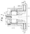
- Figs. 1 to 12 are sectional views respectively showing the structures of various embodiments of the spindle motor according to the present invention, in which the same reference numerals denote the same or corresponding portions.
- reference numeral 1 denotes a base, which has a support shaft 2 stood on the central portion thereof.
- a fixed piece 4b which constitutes a part of a radial bearing 4 is concentrically secured to the outer periphery of the support shaft 2.
- a stator coil 5 is secured to the support shaft 2 above the radial bearing 4.
- the stator coil 5 includes a plurality of electromagnetic coils equally spaced in the circumferential direction.
- a rotor 6 which serves as a hard disk supporting member has a cap-shaped configuration.
- the rotor 6 has a through-hole 16 provided in the upper end portion thereof.
- the upper end portion of the support shaft 2 extends through the through-hole 16.
- the distal end of the support shaft 2 may be secured to a stationary part (not shown).
- the upper end portion of the support shaft 2 is loosely fitted in the through-hole 16.
- the rotor 6 has an annular bearing member 7 secured to the lower end portion thereof, the bearing member 7 having an L-shaped cross-sectional configuration.
- a rotor magnet member 8 is secured to the rotor 6 above the bearing member 7.
- the rotor magnet member 8 includes a plurality of magnets or iron cores equally spaced in the circumferential direction.
- the rotor magnet member 8 and the stator coil 5 face each other across a radial gap, thus constituting a drive part of the spindle motor.
- the lower end portion of the bearing member 7 defines a movable piece 3a which constitutes a part of a thrust bearing 3.
- the movable piece 3a faces a fixed piece 3b which is secured to the base 1 to constitute another part of the thrust bearing 3.
- the inner peripheral surface of the bearing member 7 defines a movable piece 4a of the radial bearing 4.
- the movable piece 4a faces the fixed piece 4b of the radial bearing 4 that is secured to the support shaft 2.
- the opposing cylindrical sliding surfaces of the movable and fixed pieces 4a and 4b of the radial bearing 4 are made of a ceramic material, for example, silicon carbide, alumina, etc., and either of the sliding surfaces has herringbone-shaped grooves C1 for generating dynamic pressure, such as those shown in Fig. 13, the other sliding surface being smoothed.
- the opposing annular sliding surfaces of the movable and fixed pieces 3a and 3b of the thrust bearing 3 are made of a ceramic material, for example, silicon carbide, alumina, etc., and either of the annular sliding surfaces has spiral grooves C2 for generating dynamic pressure, such as those shown in Fig. 14, the other sliding surface being smoothed.
- the sliding surfaces may be made of a member coated with a kind of material different from the groundwork thereof, or may be made of a member having a treated surface of degenerated groundwork thereof, instead of the ceramic material.
- the rotor 6 is arranged such that a plurality of hard disks (not shown) can be mounted on the outer peripheral surface of the upper part of the rotor 6 through a spacer.
- the spindle motor Since the rotor 6 is supported in such a manner that the lower end and inner peripheral surfaces of the bearing member 7 are not in solid contact with the fixed piece 3b of the thrust bearing 3 and the fixed piece 4b of the radial bearing 4, the spindle motor is capable of smoothly rotating at high speed. Accordingly, the spindle motor of the present invention is free from the problem of friction and vibration in contrast to the prior art that employs ball bearings to support the rotor.
- the base 1, the support shaft 2, the fixed piece 4b of the radial bearing 4 and the fixed piece 3b of the thrust bearing 3 may be formed in an integral structure from the same constituent material.
- the movable piece 4a of the radial bearing 4 and the movable piece 3a of the thrust bearing 3 are formed in an integral structure of the bearing member 7 having an L-shaped cross section.
- the rotor 6 and the bearing member 7 may be formed in an integral structure from the same constituent material.
- the spindle motor of the present invention is suitable for use in an environment where dust must be kept out.
- the dynamic pressure generating grooves may be formed so that the dynamic pressure generated will act outwardly of the thrust bearing 3.
- a radial gap is provided between the rotor magnet member 8 and the stator coil 5, and the magnetic force center of the axial length of the rotor magnet member 8 is a distance d offset from the magnetic force center of the axial length of the stator coil 5, so that a magnetic force acts so as to make the center of the rotor magnet member 8 coincident with the center of the stator coil 5, thus enabling the thrust bearing 3 to be preloaded.
- the magnitude of the preload can be set at a desired value by varying the distance d.
- the spindle motor shown in Fig. 1 may be arranged in the form of a synchronous motor by comprising the rotor magnet member 8 of a group of rotor magnets, and may also be arranged in the form of an induction motor by comprising the rotor magnet member 8 of a group of rotor cores.
- these members that constitute the radial and thrust bearing 4 and 3 may be made of any kind of material as long as it can be machined with a high degree of accuracy. Any of generally employed metallic materials and organic materials may be utilized. The point is that it is necessary to minimize the frictional resistance and wear of the bearing members at the time when the motor is started and rotating at low speed. The range of usable materials therefore depends upon the bearing structure adopted.
- each of the radial and thrust bearings 4 and 3 is increased to reduce the surface pressure acting on the contact surfaces and the stator coil 5 is properly disposed to attain a structure which is free from any local contact. Accordingly, if the members that constitute the bearings are made of, for example, a stainless steel, and a thin coat of lubricant is applied to the contact surfaces, it is possible to maintain a stable performance for a long period of time. However, no lubricant or only minimal lubricant can be used in certain environments where the spindle motor is used. In such a case, it is preferable to employ a material which is superior in wear-resistant and sliding properties, particularly a ceramic material. Silicon carbide or alumina is particularly suitable for such an application.
- the thrust bearing 3 Since the clearance between the movable and fixed pieces of each of the thrust and radial bearings 3 and 4 is of a small value in the order of microns, the thrust bearing 3 is preferably disposed exactly at right angles with respect to the radial bearing 4. It is, however, difficult to dispose it exactly at right angles because of the limitation on the degree of accuracy with which the bearings are produced. For this reason, a resilient pad 12 which is made of a resilient material is interposed between the fixed piece 3b of the thrust bearing 3 and the base 1 to absorb any error in the perpendicularity. Any flexible and durable material may be employed to form the resilient pad 12. However, silicone rubber is suitable from the viewpoint of both flexibility and durability.
- the support shaft 2 is extended through the through-hole 16 provided in the upper end portion of the rotor 6 and the distal end of the support shaft 2 may be secured to a stationary part (not shown).
- the support shaft 2 is supported at both ends by the base 1 and the stationary part and it is therefore possible to prevent deflection of the support shaft 2 which would otherwise be caused by the weight of the load attached to the rotor 6 when the spindle motor is used in a horizontal position.
- the structure in which the support shaft 2 is supported at both ends is advantageous for use in a large-sized spindle motor.
- the radial hydrodynamic bearing 4 that comprises the movable and fixed pieces 4a and 4b is sufficiently long to cover the range of from the lower end of the support shaft 2 to the center of gravity G of a rotary assembly comprising the rotor 6 and hard disks mounted thereon.
- the effective working pressure range within which sufficient load carrying capacity is provided increases, and the radial vibration decreases.
- the radial hydrodynamic bearing 4 is not formed in a cantilever structure, the starting torque is minimized. Since the radial hydrodynamic bearing 4 is long and a large dynamic pressure is therefore generated, the movable and fixed pieces 4a and 4b of the radial bearing 4 is not required to be machined to any particularly high degree of accuracy.
- the range of preload applied in the thrust direction by the magnetic force from the rotor magnet member 8 depends on the dynamic pressure generated between the movable and fixed pieces 3a and 3b of the thrust bearing 3, the weight of the rotor 6 that is applied to the thrust bearing 3 and the machining accuracy of the movable and fixed pieces 3a and 3b of the thrust bearing 3.
- P the preload [g] applied by the rotor magnet member 8
- S the area [cm2] of the thrust bearing 3
- W the weight [g] of the rotor 6.
- 100 ⁇ S is the dynamic pressure [g/cm2] required for the rotor to rotate without solid contact through a hydrodynamic bearing finished by an existing, economical finishing process.
- the thrust bearing 3 is disposed outside the lower end of a cylindrical portion of the rotor 6, that is, the driving part comprising the rotor magnet member 8 and the stator coil 5, the diameter of the thrust bearing 3 increases, and the rotor 6 is pulled by the above-described preload toward the thrust bearing 3 having a relatively large diameter. Accordingly, the radial deflection of the rotor 6 decreases, and stable rotation of the rotor 6 is achieved.
- Fig. 2 is a sectional view showing the structure of a second embodiment of the spindle motor according to the present invention, which is similar to the first embodiment shown in Fig. 1 but different therefrom in the following point.
- the upper end of the rotor 6 is closed and not pierced by the support shaft 2.
- a member which corresponds to the annular bearing member 7 having an L-shaped cross-sectional configuration, shown in Fig. 1, is split into a radial bearing sleeve, that is, a movable piece 4a of a radial bearing, and a thrust bearing collar, that is, a movable piece 3a of a thrust bearing.
- the movable piece 4a of the radial bearing is secured to the inner peripheral surface of the rotor 6 in opposing relation to the fixed piece 4b of the radial bearing.
- the movable piece 3a of the thrust bearing is secured to the lower surface of a collar portion 17 formed at the lower end of the rotor 6, the movable piece 3a facing the fixed piece 3b of the thrust bearing.
- Fig. 3 is a sectional view showing the structure of a third embodiment of the spindle motor according to the present invention, which is similar to the embodiment shown in Fig. 2 but different therefrom in the following point.
- the rotor magnet member 8 is disposed on the ceiling of the rotor 6.
- the stator coil 5 comprises a plurality of electromagnetic coils which are secured at equal spacings to the outer periphery of the support shaft 2 above the fixed piece 4b of the radial bearing 4.
- the spindle motors shown in Figs. 1 and 2 are of the radial gap type
- the spindle motor shown in Fig. 3 is of the thrust gap type.
- the thrust gap type spindle motor is free from the moment which would otherwise be generated due to the imbalance in radial magnetic force acting between the stator coil and the rotor magnet member, and the vibration of the motor when rotating is therefore reduced.
- Fig. 4 shows the structure of a fourth embodiment of the spindle motor according to the present invention, which is similar to the embodiment shown in Fig. 1 but different therefrom in the following point.
- the base 1, the support shaft 2, the fixed piece 4b of the radial bearing and the fixed piece 3b of the thrust bearing are formed in an integral structure from the same constituent material.
- the rotor 6, the movable piece 4a of the radial bearing and the movable piece 3a of the thrust bearing are formed in an integral structure from the same constituent material.
- the support shaft 2 is extended through a through-hole 16 provided in the upper end portion of the rotor 6, and the distal end of the support shaft 2 is secured to a stationary part 42.
- Either one or both of the moving and fixed pieces of the radial and thrust bearings in the fourth embodiment may be coated with thin film of a kind of material different from that of groundwork thereof, or may be provided with a treated surface layer of degenerated groundwork thereof.
- the thin film may be made, e.g. by way of physical vapor deposition or chemical vapor deposition, or by way of plating with a kind of material different from the groundwork thereof.
- the treated surface layer may be made, e.g. by way of oxidation, nitriding, or ion implantation with the groundwork of the pieces.
- Fig. 5 shows the structure of a fifth embodiment of the spindle motor according to the present invention, which is similar to the embodiment shown in Fig. 1 but different therefrom in the following point.
- a thrust bearing 3 which has relatively small diameter is disposed below a radial bearing 4.
- the movable piece 4a of the radial bearing 4 is secured to the inner peripheral surface of the rotor 6 in opposing relation to a fixed piece 4b of the radial bearing 4 which is secured to the support shaft 2.
- the movable piece 3a of the thrust bearing 3 is secured to the inner peripheral surface of the lower end portion of the rotor 6 in opposing relation to a fixed piece 3b of the thrust bearing 3 which is secured to the base 1 through a resilient pad 12.
- a motor driving part which comprises a stator coil 5 and a rotor magnet member 8 is disposed above the radial bearing 4.
- the stator coil 5 is secured to the outer periphery of the support shaft 2 above the radial bearing 4, and the rotor magnet member 8 is secured to the inner peripheral surface of the rotor 6 in opposing relation to the stator coil 5.
- Fig. 6 shows the structure of a sixth embodiment of the spindle motor according to the present invention, which is similar to the embodiment shown in Fig. 5 but different therefrom in the following point.
- the movable pieces 3a and 4a of the thrust and radial bearings 3 and 4 are joined together in the form of an integral bearing member 7. This structure facilitates assembly of the bearings.
- Fig. 7 shows the structure of a seventh embodiment of the spindle motor according to the present invention, which is similar to the embodiment shown in Fig. 5 but different therefrom in the following point.
- the motor drive part comprises a rotor magnet member 8 which is secured to the ceiling of the rotor 6 and a stator coil 5 which is secured to the upper end of the fixed piece 4b of the radial bearing, thus forming a so-called thrust gap motor in which an axial gap is provided between the rotor magnet member 8 and the stator coil 5.
- the movable pieces 3a and 4a of the thrust and radial bearings 3 and 4 may be joined together in the form of an integral bearing member in the same way as in the spindle motor shown in Fig. 6.
- the thrust bearing 3 is formed inwardly of the outer periphery of the rotor 6 and it is therefore possible to minimize the size of the base 1, obtain a compact spindle motor and hence reduce the installation area.
- the diameter and area of the thrust bearing can be increased even if it is disposed inwardly of the outer periphery of the rotor 6, and it is possible to obtain stable rotation of the rotor 6 by preloading the thrust bearing 3 by magnetic force in a counter direction to the dynamic pressure generated from the thrust bearing 3.
- the spindle motors are not necessarily limited to synchronous motors wherein the rotor magnet member comprises magnets but may be arranged in the form of induction motors wherein the rotor magnet member comprises iron cores, as in the embodiments shown in Figs. 1 to 4.
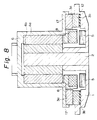
- Fig. 8 shows an eighth embodiment of the spindle motor according to the present invention.
- a fixed piece 4b of a radial bearing 4 is secured to the outer periphery of the upper part of the support shaft 2, and a movable piece 4a of the radial bearing 4 is secured to the inner periphery of a cap-shaped rotor 6.
- the rotor 6 has a horizontally extending collar portion 17 formed at the lower end thereof.
- a movable piece 3a of a thrust bearing 3 is secured to the lower surface of the collar portion 17, and a fixed piece 3a of the thrust bearing 3 is secured to a base 1 in opposing relation to the movable piece 3a.
- a rotor magnet member 8 is secured to the rotor 6 at a position which is inward of the movable piece 3b of the thrust bearing 3.
- a stator coil 5 is secured to the base 1 in opposing relation to the rotor magnet member 8. The rotor magnet member 8 and the stator coil 5 has an axial gap therebetween, thereby forming a thrust gap motor.
- the rotor 6 is arranged such that hard disks can be mounted on the outer peripheral portion of the rotor 6, and the thrust and radial bearings 3 and 4 are hydrodynamic bearings, in the same way as shown in the embodiment in Fig. 1.
- the fixed piece 4b of the radial bearing and the support shaft 2 may be formed in an integral structure, and the movable piece 4a of the radial bearing 4 and the rotor 6 may also be formed in an integral structure.
- the movable piece 3a of the thrust bearing 3 and the collar portion 17 of the rotor 6 may be formed in an integral structure, and the fixed piece 3b of the thrust bearing 3 and the base 1 may also be formed in an integral structure.
- the length of the radial bearing 4 may be made substantially the same as the height of the rotor 6, thus, the radial bearing 4 can be increased.
- Such an arrangement enables enlargement of the effective dynamic pressure range within which sufficient load carrying capacity is provided, and hence permits minimization of the radial vibration. Since the radial bearing 4 is not formed in a cantilever structure, the starting torque is minimized. In addition, the radial bearing 4 is not required to be machined to any particularly high degree of accuracy. However, the length of the radial bearing 4 may be smaller than the height of the rotor 6.
- the range of preload is the same as that expressed by the relationship (1) described above.
- the spindle motor is used in a horizontal position, stable rotation is obtained if the rotor magnet member 8 is utilized to generate a force acting counter to the dynamic pressure to thereby subject the thrust bearing 3 to a force counter to the dynamic pressure, that is, preload the thrust bearing 3.
- the thrust bearing 3 is disposed outside the drive part and hence has a relatively large diameter, so that stable rotation is obtained. By sucking in air from the outer peripheral side of the thrust bearing 3, it is possible to prevent dust from scattering outwardly from the rotor magnet member 8 and the stator coil 5.
- each of the radial and thrust bearings 4 and 3 is increased to reduce the surface pressure acting on the contact surfaces, and the stator coil 5 is properly disposed to attain a structure which is free from local contact. Accordingly, if the members that constitute the bearings are made of, for example, a stainless steel, and a thin coat of lubricant is applied to the contact surfaces, it is possible to maintain a stable performance for a long period of time. When it is not possible to use any lubricant or the thickness of lubricant should be minimized if any, it is preferable to employ a ceramic material which is superior wear-resistant and low friction properties, particularly silicon carbide or alumina.
- a resilient pad 12 is interposed between the fixed piece 3b of the thrust bearing 3 and the base 1 to absorb any error in the perpendicularity between the thrust and radial bearings 3 and 4, and the force to preload the thrust bearing 3 can be obtained from the driving part, since the driving part is a thrust gap type.
- Fig. 9 shows a ninth embodiment of the spindle motor according to the present invention, which is similar to the embodiment shown in Fig. 8 but different therefrom in the following point.
- the rotor magnet member 8 is secured to the inner peripheral of the lower part of the rotor 6 and the stator coil 5 is secured to the lower part of the support shaft 2, thereby forming a radial gap type motor.
- the center of the axial length of the stator coil 5 and that of the rotor magnet member 8 are offset from each other by a distance d, thereby enabling the thrust bearing 3 to be preloaded.
- the magnitude of the preload can be set at a desired value by varying the distance d.
- Fig. 10 shows the structure of a tenth embodiment of the spindle motor according to the present invention, which is similar to the embodiment shown in Fig. 9 but different therefrom in the following point.
- the base 1 and the fixed piece 3b of the thrust bearing 3 are formed in an integral structure from the same constituent material
- the movable piece 3a of the thrust bearing 3, the rotor 6 and the movable piece 4a of the radial bearing 4 are formed in an integral structure from the same constituent material.
- the support shaft 2 is extended through a through-hole 16 which is provided in the upper end portion of the rotor 6, and the distal end of the support shaft 2 is secured to a stationary part (not shown).
- the support shaft 2 is supported at both ends by the base 1 and the stationary part, when the spindle motor is used in a horizontal position, it is possible to prevent deflection of the support shaft 2 which would otherwise be caused by the weight of the disks attached to the rotor 6.
- the arrangement what the support shaft 2 is supported at both ends is advantageous for use in a large-sized spindle motor.
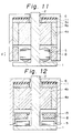
- Fig. 11 shows the structure of an eleventh embodiment of the spindle motor according to the present invention.
- a thrust bearing 3 which has a relatively small diameter is disposed between the upper end of a support shaft 2 and a cap-shaped rotor 6.
- a movable piece 3a of the thrust bearing 3 is secured to the inner surface of the upper part of the rotor 6 through a resilient pad 11.
- a movable piece 4a of a radial bearing 4 is secured to the inner peripheral surface of the rotor 6 below the movable piece 3a of the thrust bearing 3.
- a fixed piece 4b of the radial bearing 4 is concentrically secured to the outer peripheral surface of the upper part of the support shaft 2.
- the outer peripheral surface of the fixed piece 4b of the radial bearing 4 faces the inner peripheral surface of the movable piece 4a of the radial bearing 4.
- the upper end face of the fixed piece 4b defines a fixed piece 3b of the thrust bearing 3.
- the opposing cylindrical sliding surfaces of the movable and fixed pieces 4a and 4b of the radial bearing 4 are made of a ceramic material, and either of the cylindrical sliding surfaces has herringbone-shaped grooves C1 for generating dynamic pressure, such as those shown in Fig. 13.
- Either of the opposing annular sliding surfaces of the movable and fixed pieces 3a and 3b of the thrust bearing 3 has spiral grooves C2 for generating dynamic pressure, such as those shown in Fig. 14.
- a stator coil 5 is secured to the support shaft 2 below the fixed piece 4b of the radial bearing 4.
- a rotor magnet member 8 is secured to the inner peripheral surface of the lower part of the rotor 6.
- the stator coil 5 and the rotor magnet member 8 has a radial gap therebetween to constitute a radial gap motor.
- the length of the radial bearing 4 can be increased and the dynamic pressure can therefore be increased, thereby enabling the spindle motor to operate with sufficient load carrying capacity, and thus permitting minimization of radial vibration.
- the radial bearing 4 is not formed in a cantilever structure, the starting torque is minimized, and since a relatively high dynamic pressure is generated, the radial bearing 4 is not required to be machined to any particularly high degree of accuracy.
- the spindle motor is capable of stable rotation by virtue of the preload applied to the thrust bearing 3.
- Fig. 12 shows the structure of a twelfth embodiment of the spindle motor according to the present invention, which is similar to the embodiment shown in Fig. 11 but different therefrom in the following point.
- the stator coil 5 is secured to the upper surface of the base 1.
- the rotor magnet member 8 is secured to a bracket 13 which is secured to the inner peripheral surface of the lower part of the rotor 6.
- the stator coil 5 and the rotor magnet member 8 have an axial gap therebetween to constitute a thrust gap motor.
- the magnetic force acting between the stator coil 5 and the rotor magnet member 8 can be utilized to preload the thrust bearing 3 in the counter direction to the dynamic pressure generated therefrom.
Landscapes
- Engineering & Computer Science (AREA)
- General Engineering & Computer Science (AREA)
- Mechanical Engineering (AREA)
- Physics & Mathematics (AREA)
- Fluid Mechanics (AREA)
- Power Engineering (AREA)
- Sliding-Contact Bearings (AREA)
- Connection Of Motors, Electrical Generators, Mechanical Devices, And The Like (AREA)
- Turning (AREA)
- Spinning Or Twisting Of Yarns (AREA)
- Motor Or Generator Frames (AREA)
Claims (28)
- Moteur de broche comprenant un stator ayant un arbre (2) de support positionné sur une base (1), un rotor (6) en forme de capuchon disposé concentriquement autour de l'arbre de support (2) afin qu'il puisse tourner, des paliers (3, 4) de butée et radial, disposés entre le stator et le rotor, un enroulement (5) de stator fixé au stator et un organe à aimant de rotor (8) fixé au rotor (6) en face de l'enroulement (5) de stator,
dans lequel les paliers (3, 4) de butée et radial sont des paliers hydrodynamiques, le palier de butée (3) comprenant des pièces mobile et fixe (3a, 3b), la pièce mobile (3a) étant fixée à l'extrémité inférieure d'une partie cylindrique du rotor (6) et se prolongeant à l'extérieur de la partie cylindrique, la pièce fixe (3b) étant fixée à la base (1) en face de la pièce mobile (3a), l'enroulement (5) de stator étant fixé à la partie périphérique externe de l'arbre (2) de support au-dessus du palier radial (4), et l'organe à aimant de rotor (8) étant fixé à la surface périphérique interne du rotor (6) afin qu'un entrefer radial soit délimité entre l'enroulement (5) de stator et l'organe (8) à aimant de rotor. - Moteur de broche comprenant un stator ayant un arbre (2) de support dressé sur une base (1), un rotor (6) en forme de capuchon disposé concentriquement autour de l'arbre de support (2) afin qu'il puisse tourner, des paliers de butée et radial disposés entre le stator et le rotor (6), un enroulement (5) de stator fixé au stator, et un organe à aimant de rotor (8) fixé au rotor (6) en face de l'enroulement de stator,
dans lequel les paliers de butée et radial sont des paliers hydrodynamiques, le palier de butée comprenant des pièces mobile et fixe (3a, 3b), la pièce mobile (3a) étant fixée à l'extrémité inférieure d'une partie cylindrique du rotor (6) et se prolongeant à l'extérieur de la partie cylindrique, la pièce fixe (3b) étant fixée à la base en face de la pièce mobile (3a), l'enroulement (5) de stator étant fixé à la partie périphérique externe de l'arbre (2) de support au-dessus du palier radial, et l'organe à aimant de rotor (8) étant fixé à la partie supérieure du rotor (6) de manière qu'un entrefer axial soit délimité entre l'enroulement (5) de stator et l'organe à aimant de rotor (8). - Moteur de broche comprenant un stator ayant un arbre de support (2) dressé sur une base (1), un rotor (6) en forme de capuchon disposé concentriquement autour de l'arbre de support (2) afin qu'il puisse tourner, des paliers de butée et radial disposés entre le stator et le rotor (6), un enroulement (5) de stator fixé au stator, et un organe (8) à aimant de rotor fixé au rotor (6) en face de l'enroulement (5) de stator,
dans lequel les paliers de butée et radial sont des paliers hydrodynamiques, le palier de butée comprenant des pièces mobile et fixe (3a, 3b), la pièce mobile (3a) étant fixée à l'extrémité inférieure d'une partie cylindrique du rotor (6) et se prolongeant vers l'intérieur de la partie cylindrique, la pièce fixe (3b) étant fixée à la base (1) en face de la pièce mobile (3a), l'enroulement (5) de stator et l'organe à aimant de rotor (8) étant tous deux placés au-dessus du palier radial. - Moteur de broche selon la revendication 3, dans lequel l'organe à aimant de rotor (8) est fixé à la partie supérieure du rotor (6) de manière qu'un entrefer axial soit formé entre l'enroulement (5) de stator et l'organe à aimant de rotor (8).
- Moteur de broche comprenant un stator ayant un arbre de support (2) disposé sur une base (1), un rotor (6) en forme de capuchon disposé concentriquement autour de l'arbre de support (2) afin qu'il puisse tourner, des paliers de butée et radial disposés entre le stator et le rotor (6), un enroulement (5) de stator fixé au stator, et un organe à aimant de rotor (8) fixé au rotor (6) en face de l'enroulement (5) de stator,
dans lequel les paliers de butée et radial sont des paliers hydrodynamiques, le palier de butée comprenant des pièces mobile et fixe (3a, 3b), la pièce mobile (3a) étant fixée à l'extrémité inférieure d'une partie cylindrique du rotor (6) et se prolongeant à l'extérieur de la partie cylindrique, la pièce fixe (3b) étant fixée à la base (1) en face de la pièce mobile (3a) et l'organe à aimant de rotor (8) étant fixé au rotor (6)en une position qui se trouve à l'intérieur de la pièce mobile (3a) du palier de butée. - Moteur de broche selon la revendication 5, dans lequel l'enroulement (5) de stator est fixé à la base (1) de manière qu'un entrefer axial soit formé entre l'enroulement (5) de stator et l'organe à aimant de rotor (8).
- Moteur de broche selon la revendication 5, dans lequel l'enroulement (5) de stator est fixé à la partie inférieure de l'arbre de support (2) afin qu'un entrefer radial soit formé entre l'enroulement (5) de stator et l'organe à aimant de rotor (8).
- Moteur de broche comprenant un stator ayant un arbre de support (2) disposé sur une base (1), un rotor (6) en forme de capuchon disposé concentriquement autour de l'arbre de support (2) afin qu'il puisse tourner, des paliers de butée et radial disposés entre le stator et le rotor (6), un enroulement (5) de stator fixé au stator, et un organe à aimant de rotor (8) fixé au rotor (6) en face de l'enroulement (5) de stator,
dans lequel les paliers de butée et radial sont des paliers hydrodynamiques, le palier de butée étant placé au-dessus du palier radial, et l'enroulement (5) de stator et l'organe à aimant de rotor (8) étant placés au-dessous du palier radial. - Moteur de broche selon la revendication 8, dans lequel l'enroulement (5) de stator est fixé à la base (1) afin qu'un entrefer axial soit formé entre l'enroulement (5) de stator et l'organe à aimant de rotor (8).
- Moteur de broche selon l'une quelconque des revendications 1 à 9, dans lequel le palier de butée (3) est soumis à une force préalable due à une force magnétique agissant à l'opposé de la pression dynamique qui agit dans le sens de poussée.
- Moteur de broche selon l'une quelconque des revendications 1, 3, 5, 7 et 8, dans lequel le centre axial de l'organe à aimant de rotor (8) est décalé par rapport au centre axial de l'enroulement (5) de stator d'une distance prédéterminée (d) en sens opposé à celui de l'effet de la pression dynamique créée par le palier de butée, si bien qu'une force préalable est appliquée au palier de butée dans le sens qui s'oppose à l'action de la pression dynamique dans la direction de poussée.
- Moteur de broche selon l'une quelconque des revendications 1 à 9, dans lequel le palier radial (4) est disposé afin qu'il porte le rotor dans une plage prédéterminée comprenant le centre de gravité du rotor.
- Moteur de broche selon l'une quelconque des revendications 1 à 9, dans lequel la pièce fixe (3b) du palier de butée est fixée au stator par un patin élastique (12).
- Moteur de broche selon la revendication 13, dans lequel le patin élastique (12) est formé de caoutchouc de silicone.
- Moteur de broche selon l'une quelconque des revendications 1 à 9, dans lequel la pièce mobile (3a) du palier de butée est fixée au rotor par un patin élastique (11).
- Moteur de broche selon la revendication 15, dans lequel le patin élastique (11) est formé de caoutchouc de silicone.
- Moteur de broche selon l'une quelconque des revendications 1 à 9, dans lequel les surfaces annulaires opposées de glissement des pièces fixe et mobile (3a, 3b) du palier de butée sont formées d'une matière céramique ou d'un organe revêtu d'un type de matière différent de celui de la surface usinée ou d'un organe ayant une surface traitée à partir de la matière usinée dégénérée, et l'une des surfaces de glissement a des gorges spiralées permettant la création d'une pression dynamique.
- Moteur de broche selon la revendication 17, dans lequel la matière céramique est le carbure de silicium ou l'alumine.
- Moteur de broche selon l'une quelconque des revendication 1 à 9, dans lequel les surfaces cylindriques opposées de glissement des pièces fixe et mobile (4a, 4b) du palier radial sont formées d'un matériau céramique ou d'un organe revêtu d'un type de matériau différent de celui de la surface usinée ou d'un organe ayant une surface traitée à partir de la matière de la surface usinée dégénérée, et l'une des surfaces cylindriques de glissement a des gorges en chevrons pour la création d'une pression dynamique.
- Moteur de broche selon la revendication 19, dans lequel la matière céramique est le carbure de silicium ou l'alumine.
- Moteur de broche selon l'une quelconque des revendications 1, 4, 8 et 9, dans lequel une partie ou la totalité de la pièce mobile (4a) du palier radial, du rotor (6) et de la pièce mobile (3a) du palier de butée sont disposées sous forme d'une structure solidaire.
- Moteur de broche selon la revendication 21, dans lequel l'une des deux ou les deux pièces mobiles (3a, 4a) des paliers radial et de butée de la structure solidaire est revêtue d'un type de matière différent de celui de la surface usinée, ou la surface usinée a subi un traitement de surface.
- Moteur de broche selon l'une quelconque des revendications 1, 2, 8 et 9, dans lequel une partie ou la totalité de la pièce fixe (4b) du palier radial, de l'arbre de support (2), de la pièce fixe (3b) du palier de butée et de la base (1) est sous forme d'une structure solidaire.
- Moteur de broche selon la revendication 23, dans lequel l'une au moins des pièces fixes (3b, 4b) des paliers radial et de butée de la structure solidaire est revêtue d'un type de matière différent de celui de la surface usinée, ou la surface usinée a subi un traitement de surface.
- Moteur de broche selon l'une quelconque des revendications 1 à 9, dans lequel le rotor (6) a un organe de support destiné à supporter des disques durs à sa surface périphérique externe.
- Moteur de broche selon l'une quelconque des revendications 1 à 9, dans lequel l'arbre de support (2) est prolongé par un trou débouchant (16) formé à la partie d'extrémité supérieure du rotor (6), et l'arbre de support (2) est logé avec du jeu dans le trou débouchant (16).
- Moteur de broche selon la revendication 26, dans lequel l'extrémité externe de l'arbre de support (2) est fixée à une partie fixe (42).
- Moteur de broche selon l'une quelconque des revendications 1 à 9, dans lequel l'extrémité supérieure du rotor (6) est fermée et n'est pas traversée par l'arbre de support (2).
Applications Claiming Priority (8)
| Application Number | Priority Date | Filing Date | Title |
|---|---|---|---|
| JP9216189 | 1989-04-12 | ||
| JP92161/89 | 1989-04-12 | ||
| JP179647/89 | 1989-07-12 | ||
| JP17964789 | 1989-07-12 | ||
| JP20507789 | 1989-08-08 | ||
| JP205077/89 | 1989-08-08 | ||
| JP22367989 | 1989-08-30 | ||
| JP223679/89 | 1989-08-30 |
Publications (3)
| Publication Number | Publication Date |
|---|---|
| EP0392500A2 EP0392500A2 (fr) | 1990-10-17 |
| EP0392500A3 EP0392500A3 (fr) | 1991-05-02 |
| EP0392500B1 true EP0392500B1 (fr) | 1995-03-01 |
Family
ID=27468002
Family Applications (1)
| Application Number | Title | Priority Date | Filing Date |
|---|---|---|---|
| EP90106941A Expired - Lifetime EP0392500B1 (fr) | 1989-04-12 | 1990-04-11 | Moteur à broche |
Country Status (5)
| Country | Link |
|---|---|
| US (1) | US4998033A (fr) |
| EP (1) | EP0392500B1 (fr) |
| AT (1) | ATE119306T1 (fr) |
| DE (1) | DE69017248T2 (fr) |
| ES (1) | ES2071696T3 (fr) |
Families Citing this family (55)
| Publication number | Priority date | Publication date | Assignee | Title |
|---|---|---|---|---|
| USRE34684E (en) * | 1987-05-08 | 1994-08-02 | Nagano Nidec Corporation | Drive motor for magnetic disks, optical disks, and magneto-optical disks |
| EP0410293B1 (fr) * | 1989-07-24 | 1993-09-29 | Ebara Corporation | Moteur arbre |
| US5193084A (en) * | 1989-11-15 | 1993-03-09 | U.S. Philips Corporation | Device for rotating a disc-shaped information carrier including a turntable and frame |
| JPH068647B2 (ja) * | 1990-06-27 | 1994-02-02 | 株式会社荏原製作所 | スラスト動圧軸受の起動・停止装置 |
| DE4121428A1 (de) * | 1991-06-28 | 1993-01-07 | Papst Motoren Gmbh & Co Kg | Spindelmotor, insbesondere fuer plattenspeicher |
| DE59209596D1 (de) * | 1991-06-29 | 1999-02-04 | Papst Motoren Gmbh & Co Kg | Plattenspeicherantrieb |
| DE4221429C2 (de) * | 1991-07-01 | 1999-01-14 | Papst Motoren Gmbh & Co Kg | Plattenspeicherantrieb, insbesondere für Festplattenspeicher |
| DE69125836T2 (de) * | 1991-11-14 | 1997-12-18 | Quantum Corp | Spindel- und Nabenausrüstung |
| US5328272A (en) * | 1991-12-23 | 1994-07-12 | International Business Machines | Spindle system for a disk drive |
| JPH05240241A (ja) * | 1992-02-28 | 1993-09-17 | Ebara Corp | スピンドルモータ |
| US5473485A (en) * | 1992-03-06 | 1995-12-05 | Read-Rite Corporation | Tripad air bearing magnetic head slider |
| JP2696033B2 (ja) * | 1992-03-30 | 1998-01-14 | 株式会社東芝 | ディスク装置用スピンドルモータ |
| US5161900A (en) * | 1992-04-10 | 1992-11-10 | International Business Machines, Corp. | Self-contained low power fluid bearing and bearing seal |
| US5559382A (en) * | 1992-10-01 | 1996-09-24 | Nidec Corporation | Spindle motor |
| JP2500731B2 (ja) * | 1992-11-12 | 1996-05-29 | 日本電気株式会社 | 磁気ディスク装置用スピンドルモ―タ |
| JPH06173944A (ja) * | 1992-12-03 | 1994-06-21 | Ebara Corp | 気体動圧軸受 |
| US5283491A (en) * | 1993-01-11 | 1994-02-01 | Maxtor Corporation | Air-bearing motor assembly for magnetic recording systems |
| DE69425119T2 (de) * | 1993-12-14 | 2001-02-15 | Hitachi, Ltd. | Aufzeichnungsplattengerät und rotierende Halterungsstruktur dafür |
| US5973878A (en) * | 1993-12-14 | 1999-10-26 | Hitachi, Ltd. | Recording disk apparatus and rotational supporting structure therefor, having a magnetic lubricant seal which is inclined |
| DE4401262C2 (de) * | 1994-01-18 | 1997-07-03 | Langenbeck Peter | Aerostatische und aerodynamische Lagerung eines Motors |
| EP0670621B1 (fr) * | 1994-03-04 | 2000-12-06 | Philips Patentverwaltung GmbH | Moteur électrique avec un stateur et un roteur |
| JPH0833268A (ja) * | 1994-07-19 | 1996-02-02 | Toshiba Corp | アキシャルギャップ形モータ及びポリゴンミラー駆動用スキャナモータ |
| US5500780A (en) * | 1994-08-05 | 1996-03-19 | International Business Machines Corporation | Disk drive spindle motor having split windings for each phase |
| US6119348A (en) * | 1996-12-16 | 2000-09-19 | Seagate Technology Llc | Air gaging for setting gaps in hydrodynamic bearings |
| US5921731A (en) * | 1996-12-31 | 1999-07-13 | The Ingersoll Milling Machine Company | High speed hydrostatic spindle |
| US6036413A (en) * | 1997-01-02 | 2000-03-14 | The Ingersoll Milling Machine Company | High speed hydrodynamic spindle |
| US6025665A (en) * | 1997-02-21 | 2000-02-15 | Emerson Electric Co. | Rotating machine for use in a pressurized fluid system |
| US6078121A (en) * | 1997-02-21 | 2000-06-20 | Emerson Electric Co. | Rotor assembly for a rotating machine |
| US5834869A (en) * | 1997-06-02 | 1998-11-10 | Emerson Electric Co. | Blower motor housing |
| US5957589A (en) * | 1997-12-10 | 1999-09-28 | International Business Machine Corporation | Fluid bearing seal and support structure |
| US6148501A (en) * | 1998-04-14 | 2000-11-21 | Seagate Technology Llc | Fabrication means for in-hub spindle with separate fluid dynamic bearings |
| JP2000074043A (ja) * | 1998-06-17 | 2000-03-07 | Mitsubishi Electric Corp | スピンドルモ―タ |
| US6456458B1 (en) * | 1998-08-08 | 2002-09-24 | Nidec Corporation | Disk-drive motor rotating on a magnetically counterbalanced single hydrodynamic thrust bearing |
| JP3466945B2 (ja) * | 1999-01-05 | 2003-11-17 | 日本電産株式会社 | 記録ディスク駆動用モータ及びこれを備えた記録ディスク駆動装置 |
| JP2000350408A (ja) * | 1999-03-29 | 2000-12-15 | Nippon Densan Corp | 記録ディスク駆動用モータ |
| JP2003222124A (ja) * | 1999-07-14 | 2003-08-08 | Sumitomo Electric Ind Ltd | スピンドルモータ |
| US6313967B1 (en) | 1999-08-03 | 2001-11-06 | Maxtor Corporation | Disk drive spindle air bearing |
| US6483215B1 (en) | 1999-10-13 | 2002-11-19 | Maxtor Corporation | Hybrid air/fluid bearing |
| JP2002122137A (ja) * | 2000-10-10 | 2002-04-26 | Sankyo Seiki Mfg Co Ltd | 軸受装置 |
| US6502991B2 (en) | 2001-03-14 | 2003-01-07 | The Timken Company | Rotary fluid bearing coatings and coining and processes for manufacturing the same |
| US7249363B2 (en) * | 2001-07-17 | 2007-07-24 | Matsushita Electric Industrial Co., Ltd. | Spindle motor, information recording and reproducing apparatus having a spindle motor, and manufacturing method of spindle motor |
| IL145321A0 (en) | 2001-09-06 | 2002-06-30 | Micro Tools Ltd | Improved dental drill head configuration |
| JP3828452B2 (ja) * | 2002-04-18 | 2006-10-04 | 日本電産株式会社 | スピンドルモータ及びこのスピンドルモータを用いたディスク駆動装置 |
| US7422370B2 (en) * | 2002-08-06 | 2008-09-09 | Seagate Technology Llc | Hydraulic compensation for magnetically biased fluid dynamic bearing motor |
| US6841902B2 (en) * | 2002-10-07 | 2005-01-11 | Seagate Technology Llc | Method and apparatus for minimization of magnetic bias force harmonics in a spindle motor |
| US7265939B2 (en) * | 2003-03-31 | 2007-09-04 | Matsushita Electric Industrial Co., Ltd. | Spindle motor and disk drive unit |
| US7122922B2 (en) * | 2003-05-20 | 2006-10-17 | Seagate Technology Llc | Base plate for spindle motor |
| US6920013B2 (en) * | 2003-11-07 | 2005-07-19 | Nidec Corporation | Disk drive spindle motor with radial inward thrust area annular protruding portion and bearing member communicating passage |
| DE10361229B4 (de) * | 2003-12-24 | 2012-01-26 | Minebea Co., Ltd. | Spindelmotor mit Lagersystem |
| US7956499B2 (en) * | 2005-06-02 | 2011-06-07 | Seagate Technology Llc | Motor magnetic force attenuator |
| US7692892B2 (en) * | 2006-07-19 | 2010-04-06 | Seagate Technology Llc | Two-material base for a data storage system |
| DE102011101827A1 (de) * | 2011-05-17 | 2012-11-22 | Minebea Co., Ltd. | Spindelmotor mit einem Bauteil aus Chromstahl |
| US10260560B2 (en) | 2013-12-04 | 2019-04-16 | Us Synthetic Corporation | Compact bearing assemblies including superhard bearing surfaces, bearing apparatuses, and methods of use |
| US9410576B2 (en) * | 2013-12-04 | 2016-08-09 | Us Synthetic Corporation | Compact bearing assemblies including superhard bearing surfaces, bearing apparatuses, and methods of use |
| US12431162B2 (en) * | 2022-11-15 | 2025-09-30 | Western Digital Technologies, Inc. | Rotating electromagnet for removable disk clamp |
Family Cites Families (15)
| Publication number | Priority date | Publication date | Assignee | Title |
|---|---|---|---|---|
| GB1524662A (en) * | 1977-03-24 | 1978-09-13 | Univ Southampton | Agnetic disc stores |
| JPS58142025A (ja) * | 1982-02-13 | 1983-08-23 | Toshiba Corp | スピンドル装置 |
| JPS5928757A (ja) * | 1982-08-11 | 1984-02-15 | Takahashi Yoshiteru | 回転多面鏡走査装置 |
| US4509160A (en) * | 1983-12-05 | 1985-04-02 | Eggers Fred S | Disc drive assembly |
| US4604229A (en) * | 1985-03-20 | 1986-08-05 | Ferrofluidics Corporation | Electrically conductive ferrofluid compositions and method of preparing and using same |
| US4726640A (en) * | 1985-09-24 | 1988-02-23 | Ricoh Company, Ltd. | Optical deflector with a pneumatic and a magnetic bearing |
| JPH0691717B2 (ja) * | 1986-09-26 | 1994-11-14 | 株式会社荏原製作所 | 電動機械 |
| JPS63100416A (ja) * | 1986-10-17 | 1988-05-02 | Ricoh Co Ltd | 光偏向装置 |
| JP2602648B2 (ja) * | 1987-01-14 | 1997-04-23 | キヤノン株式会社 | 回転駆動装置 |
| US4824122A (en) * | 1987-03-02 | 1989-04-25 | Ferrofluidics Corporation | Compact magnetic fluid low pressure seal |
| JPS63241517A (ja) * | 1987-03-30 | 1988-10-06 | Ebara Corp | ポリゴンミラ− |
| JPS63241515A (ja) * | 1987-03-30 | 1988-10-06 | Ebara Corp | ポリゴンミラ− |
| JPS63241516A (ja) * | 1987-03-30 | 1988-10-06 | Ebara Corp | ポリゴンミラ− |
| JPH01200320A (ja) * | 1988-02-05 | 1989-08-11 | Hitachi Ltd | 回転鏡光偏向器 |
| FR2627313B1 (fr) * | 1988-02-12 | 1994-08-05 | Mecanique Magnetique Sa | Dispositif de suspension et d'entrainement de disques de memoire d'ordinateur |
-
1990
- 1990-04-09 US US07/506,183 patent/US4998033A/en not_active Expired - Fee Related
- 1990-04-11 DE DE69017248T patent/DE69017248T2/de not_active Expired - Fee Related
- 1990-04-11 EP EP90106941A patent/EP0392500B1/fr not_active Expired - Lifetime
- 1990-04-11 AT AT90106941T patent/ATE119306T1/de not_active IP Right Cessation
- 1990-04-11 ES ES90106941T patent/ES2071696T3/es not_active Expired - Lifetime
Also Published As
| Publication number | Publication date |
|---|---|
| ES2071696T3 (es) | 1995-07-01 |
| EP0392500A3 (fr) | 1991-05-02 |
| EP0392500A2 (fr) | 1990-10-17 |
| DE69017248T2 (de) | 1995-10-26 |
| DE69017248D1 (de) | 1995-04-06 |
| ATE119306T1 (de) | 1995-03-15 |
| US4998033A (en) | 1991-03-05 |
Similar Documents
| Publication | Publication Date | Title |
|---|---|---|
| EP0392500B1 (fr) | Moteur à broche | |
| EP0410293B1 (fr) | Moteur arbre | |
| US5142173A (en) | Bearing structure | |
| US5969448A (en) | Electric spindle motor | |
| US5358339A (en) | Hydrodynamic fluid bearing with liquid-radial bearing and gas-thrust bearing | |
| US5289067A (en) | Bearing device | |
| US5210665A (en) | Floppy disk apparatus having an improved disk rotating mechanism | |
| US6955469B2 (en) | Dynamic pressure bearing device | |
| KR20020016412A (ko) | 유체동압 베어링 모터 | |
| JP2000074043A (ja) | スピンドルモ―タ | |
| JP2505916B2 (ja) | 軸受け構造 | |
| EP0720167B1 (fr) | Moteur sans balai du type plat | |
| US7465097B2 (en) | Fluid dynamic bearing system | |
| US6822825B2 (en) | Stiffness compensation for a thermally compensated fluid dynamic bearing | |
| JP4063600B2 (ja) | 動圧軸受電動機 | |
| JPH102329A (ja) | 軸受装置 | |
| JPH03159552A (ja) | スピンドルモータ | |
| JPH03159551A (ja) | スピンドルモータ | |
| JPH0757079B2 (ja) | スピンドルモータ | |
| JPH03128649A (ja) | スピンドルモータ | |
| JPH09250543A (ja) | 軸受装置及びモータ並びにポリゴンミラー駆動用スキャナモータ | |
| JP2002159157A (ja) | 動圧空気軸受モータ | |
| JP4147086B2 (ja) | スピンドルモータ及びこのスピンドルモータを備えたディスク駆動装置 | |
| JP2000253619A (ja) | 動圧軸受モータ | |
| JPH09329137A (ja) | 玉軸受装置 |
Legal Events
| Date | Code | Title | Description |
|---|---|---|---|
| PUAI | Public reference made under article 153(3) epc to a published international application that has entered the european phase |
Free format text: ORIGINAL CODE: 0009012 |
|
| AK | Designated contracting states |
Kind code of ref document: A2 Designated state(s): AT BE CH DE ES FR GB IT LI NL SE |
|
| PUAL | Search report despatched |
Free format text: ORIGINAL CODE: 0009013 |
|
| AK | Designated contracting states |
Kind code of ref document: A3 Designated state(s): AT BE CH DE ES FR GB IT LI NL SE |
|
| 17P | Request for examination filed |
Effective date: 19910820 |
|
| 17Q | First examination report despatched |
Effective date: 19931018 |
|
| ITF | It: translation for a ep patent filed | ||
| GRAA | (expected) grant |
Free format text: ORIGINAL CODE: 0009210 |
|
| AK | Designated contracting states |
Kind code of ref document: B1 Designated state(s): AT BE CH DE ES FR GB IT LI NL SE |
|
| REF | Corresponds to: |
Ref document number: 119306 Country of ref document: AT Date of ref document: 19950315 Kind code of ref document: T |
|
| REF | Corresponds to: |
Ref document number: 69017248 Country of ref document: DE Date of ref document: 19950406 |
|
| ET | Fr: translation filed | ||
| REG | Reference to a national code |
Ref country code: ES Ref legal event code: FG2A Ref document number: 2071696 Country of ref document: ES Kind code of ref document: T3 |
|
| PLBE | No opposition filed within time limit |
Free format text: ORIGINAL CODE: 0009261 |
|
| STAA | Information on the status of an ep patent application or granted ep patent |
Free format text: STATUS: NO OPPOSITION FILED WITHIN TIME LIMIT |
|
| 26N | No opposition filed | ||
| PGFP | Annual fee paid to national office [announced via postgrant information from national office to epo] |
Ref country code: SE Payment date: 20010215 Year of fee payment: 12 |
|
| PGFP | Annual fee paid to national office [announced via postgrant information from national office to epo] |
Ref country code: AT Payment date: 20010308 Year of fee payment: 12 |
|
| PGFP | Annual fee paid to national office [announced via postgrant information from national office to epo] |
Ref country code: BE Payment date: 20010313 Year of fee payment: 12 |
|
| PGFP | Annual fee paid to national office [announced via postgrant information from national office to epo] |
Ref country code: CH Payment date: 20010314 Year of fee payment: 12 |
|
| PGFP | Annual fee paid to national office [announced via postgrant information from national office to epo] |
Ref country code: FR Payment date: 20010315 Year of fee payment: 12 |
|
| PGFP | Annual fee paid to national office [announced via postgrant information from national office to epo] |
Ref country code: GB Payment date: 20010327 Year of fee payment: 12 |
|
| PGFP | Annual fee paid to national office [announced via postgrant information from national office to epo] |
Ref country code: ES Payment date: 20010416 Year of fee payment: 12 |
|
| PGFP | Annual fee paid to national office [announced via postgrant information from national office to epo] |
Ref country code: NL Payment date: 20010427 Year of fee payment: 12 |
|
| PGFP | Annual fee paid to national office [announced via postgrant information from national office to epo] |
Ref country code: DE Payment date: 20010430 Year of fee payment: 12 |
|
| REG | Reference to a national code |
Ref country code: GB Ref legal event code: IF02 |
|
| PG25 | Lapsed in a contracting state [announced via postgrant information from national office to epo] |
Ref country code: GB Free format text: LAPSE BECAUSE OF NON-PAYMENT OF DUE FEES Effective date: 20020411 Ref country code: AT Free format text: LAPSE BECAUSE OF NON-PAYMENT OF DUE FEES Effective date: 20020411 |
|
| PG25 | Lapsed in a contracting state [announced via postgrant information from national office to epo] |
Ref country code: SE Free format text: LAPSE BECAUSE OF NON-PAYMENT OF DUE FEES Effective date: 20020412 Ref country code: ES Free format text: LAPSE BECAUSE OF NON-PAYMENT OF DUE FEES Effective date: 20020412 |
|
| PG25 | Lapsed in a contracting state [announced via postgrant information from national office to epo] |
Ref country code: LI Free format text: LAPSE BECAUSE OF NON-PAYMENT OF DUE FEES Effective date: 20020430 Ref country code: CH Free format text: LAPSE BECAUSE OF NON-PAYMENT OF DUE FEES Effective date: 20020430 Ref country code: BE Free format text: LAPSE BECAUSE OF NON-PAYMENT OF DUE FEES Effective date: 20020430 |
|
| PG25 | Lapsed in a contracting state [announced via postgrant information from national office to epo] |
Ref country code: NL Free format text: LAPSE BECAUSE OF NON-PAYMENT OF DUE FEES Effective date: 20021101 Ref country code: DE Free format text: LAPSE BECAUSE OF NON-PAYMENT OF DUE FEES Effective date: 20021101 |
|
| EUG | Se: european patent has lapsed |
Ref document number: 90106941.9 |
|
| GBPC | Gb: european patent ceased through non-payment of renewal fee |
Effective date: 20020411 |
|
| REG | Reference to a national code |
Ref country code: CH Ref legal event code: PL |
|
| PG25 | Lapsed in a contracting state [announced via postgrant information from national office to epo] |
Ref country code: FR Free format text: LAPSE BECAUSE OF NON-PAYMENT OF DUE FEES Effective date: 20021231 |
|
| NLV4 | Nl: lapsed or anulled due to non-payment of the annual fee |
Effective date: 20021101 |
|
| REG | Reference to a national code |
Ref country code: FR Ref legal event code: ST |
|
| REG | Reference to a national code |
Ref country code: ES Ref legal event code: FD2A Effective date: 20030514 |
|
| PG25 | Lapsed in a contracting state [announced via postgrant information from national office to epo] |
Ref country code: IT Free format text: LAPSE BECAUSE OF NON-PAYMENT OF DUE FEES;WARNING: LAPSES OF ITALIAN PATENTS WITH EFFECTIVE DATE BEFORE 2007 MAY HAVE OCCURRED AT ANY TIME BEFORE 2007. THE CORRECT EFFECTIVE DATE MAY BE DIFFERENT FROM THE ONE RECORDED. Effective date: 20050411 |