EP0392909A1 - Elastische, hydraulisch gedämpfte Buchse mit radialer Elastizität und Entkoppelung der Steifigkeiten - Google Patents
Elastische, hydraulisch gedämpfte Buchse mit radialer Elastizität und Entkoppelung der Steifigkeiten Download PDFInfo
- Publication number
- EP0392909A1 EP0392909A1 EP90400954A EP90400954A EP0392909A1 EP 0392909 A1 EP0392909 A1 EP 0392909A1 EP 90400954 A EP90400954 A EP 90400954A EP 90400954 A EP90400954 A EP 90400954A EP 0392909 A1 EP0392909 A1 EP 0392909A1
- Authority
- EP
- European Patent Office
- Prior art keywords
- thin wall
- chambers
- damping
- sleeve
- walls
- Prior art date
- Legal status (The legal status is an assumption and is not a legal conclusion. Google has not performed a legal analysis and makes no representation as to the accuracy of the status listed.)
- Granted
Links
Images
Classifications
-
- F—MECHANICAL ENGINEERING; LIGHTING; HEATING; WEAPONS; BLASTING
- F16—ENGINEERING ELEMENTS AND UNITS; GENERAL MEASURES FOR PRODUCING AND MAINTAINING EFFECTIVE FUNCTIONING OF MACHINES OR INSTALLATIONS; THERMAL INSULATION IN GENERAL
- F16F—SPRINGS; SHOCK-ABSORBERS; MEANS FOR DAMPING VIBRATION
- F16F13/00—Units comprising springs of the non-fluid type as well as vibration-dampers, shock-absorbers, or fluid springs
- F16F13/04—Units comprising springs of the non-fluid type as well as vibration-dampers, shock-absorbers, or fluid springs comprising both a plastics spring and a damper, e.g. a friction damper
- F16F13/06—Units comprising springs of the non-fluid type as well as vibration-dampers, shock-absorbers, or fluid springs comprising both a plastics spring and a damper, e.g. a friction damper the damper being a fluid damper, e.g. the plastics spring not forming a part of the wall of the fluid chamber of the damper
- F16F13/08—Units comprising springs of the non-fluid type as well as vibration-dampers, shock-absorbers, or fluid springs comprising both a plastics spring and a damper, e.g. a friction damper the damper being a fluid damper, e.g. the plastics spring not forming a part of the wall of the fluid chamber of the damper the plastics spring forming at least a part of the wall of the fluid chamber of the damper
- F16F13/14—Units of the bushing type, i.e. loaded predominantly radially
Definitions
- the invention relates to the field of antivibration insulations of machines, more particularly the elastic supports of automobile engines or of heavy vehicle cabins. It relates to the family of elastic supports, produced by combining elastomeric walls and rigid rings, the shape of the assembly being substantially of revolution. These devices are designated by the term elastic sleeves, the deformability being used essentially radially. Said devices have the function of reacting to alternating forces in a preferred direction perpendicular to the axis while carrying a more or less high permanent load. In the main direction of work, damping by hydraulic means is fundamentally associated with the dynamic rigidity presented by said devices to the various stresses.
- a first family of elastic suspensions the rigidity of which is ensured by elastomer parts, with integrated hydraulic damping of movements in the same direction as that of the load - the load being arranged in the axis of the parts of revolution -, has received a recent development by the integration of a long inertial column of non-viscous liquid whose resonant effect blocks the apparent rigidity as soon as the alternating stresses exceed a certain range of frequencies.
- the highly resonant system by definition, has a coefficient of transmission of accelerations resulting from alternating stresses much greater than 1.
- "Decoupling in rigidity” consists in releasing - therefore considerably lowering - the apparent rigidity of the system to inertia, on the very small strokes which characterize high frequency vibrations.
- a short stroke device is interposed in series with the apparent rigidity, in different forms, its efficiency going in the same direction as a weak inertia.
- Patent EP 0.278.801 filed by Rubber Manufactured and Plastics, includes, for this purpose, the simultaneous fitting of four tubes allowing the formation of the chambers, the communication channel with a resonant column, and thin membranes for decoupling, these terms having become in common use in the prior art.
- the mass of the resonant column, connecting the two chambers acts in an inverse ratio of its section compared to the equivalent section of a piston which would transfer the same volume of liquid under the offset effect.
- the present invention aims to simplify the previous arrangements by combining a minimum number of parts, the simplest possible, to obtain the same results as those of complex devices known from the prior art.
- the very long channel containing the resonant column remains defined by a groove between rigid tubes, provided by the assembly of the outer rings and the elastic walls of two opposite chambers.
- the decoupling in rigidity is ensured by the deformation, of small amplitude, of a wall located closest to the inner ring of the two chambers.
- the lowest inertia is obtained by the presence of air behind thin walls and experience teaches that the movement of this fragile wall must be geometrically limited by pressing on a grid, on one side or the other.
- the invention therefore consists of an elastic antivibration isolation device consisting of a sleeve, with deformable side walls, with hydraulic damping of the radial elasticity by circulation of liquid between two upper and lower chambers through a long annular channel. formed in the periphery of a round external fixing frame.
- the invention further comprises a decoupling in rigidity, over a short stroke, ensured by the deformation of a thin wall closing each of the chambers, geometrically limited deformation by pressing on the internal fixing ring of the inner face, bathed in air.
- the invention is characterized in that said thin wall abuts on a comb integrated into said internal fixing ring, by its outer face, in contact with the damping liquid, and in that the seal between the two upper chambers (13) and lower (14), provided by the reciprocal support of two partition walls (12), which are an integral part of said side walls (11), is limited in pressure by their detachment which allows said chambers to communicate with each other, in the event of an impact.
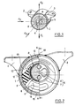
- Figure 1 is a perspective view showing the different axes of use of the elastic sleeve part, used as one of the engine supports of an automobile powertrain, with a permanent load directed in the direction F1.
- Said permanent load, at rest, can be of small value compared to the dynamic variations due to the resumption of torque, which are alternated between the opposite directions F1 and F4.
- the perpendicular direction F2 represents the direction transverse to the vehicle in which the prescribed radial stiffness does not need to be damped. It is the same for the longitudinal direction along F3, along which the axial rigidity of the elastic part is ensured.
- the latter consists of a round external fixing frame (1), made of metal tube welded to fixing ears (2) and (3), generally coming to bear on elements of the chassis, by bolting.
- the attachment to the motor which is suspended from it is made by a solid ring (4), for example made of aluminum alloy, pierced with fixing holes (5) and lightening recesses, which may prove to be necessary.
- a solid ring (4) for example made of aluminum alloy, pierced with fixing holes (5) and lightening recesses, which may prove to be necessary.
- On said massive ring (4) are fitted the various elements constituting the assembly of the internal fixing ring (6).
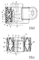
- Figure 2 is a half view / half section, through a plane perpendicular to the axis, of the piece forming an elastic sleeve.
- the round external fixing frame (1) constitutes, with the fixing lugs (2) and (3) which are welded to it, an assembly then receiving the protection against oxidation usual with steel sheet reinforcements.
- the solid ring (4) is also seen in the half-section, as well as a half-ring (7), fitted on it during assembly to constitute the internal fixing ring (6). Also visible in the section are the two thin walls (8), characteristic of the invention, surrounded by an outer half-ring (9), fitted to the assembly in the round external fixing frame (1).
- the fitted surface provides, in the plane of the section, an annular channel (10), through which the resonant column of damping liquid circulates.
- a half-ring (7) provided with windows and an outer half-ring (9) are intimately linked, during manufacture, by an elastic side wall (11).
- partition wall (12) is shown, which is an integral part of said side wall (11), seen at the bottom of the section.
- Figure 3 explains the operation of the hydraulic damping integrated in the elastic sleeve. It is a half-section through a vertical plane A, passing through the axis. After static deflection, for example from 2 to 3 millimeters, side walls (11), manufactured eccentric and partitions, the most massive parts of which, which are an integral part, the internal fixing ring (6) and the round outer fixing frame (1) become substantially concentric.
- the section shows how the two outer half-rings (9), locally constricted over a few millimeters on either side of the median plane, can provide the annular channel (10), between them and the round external fixing frame ( 1). Either one overlapping the other, as shown, or both cylindrical with constriction over part of their length, said outer half-rings (9) can come into contact with one another.
- the poor sealing obtained by the edge contact between steel sheets end to end, can act on the free circulation of the liquid in the annular channel (10), the effect being to widen, in frequency, the resonant system, which may be appropriate in some applications.
- the seal provided by mutual support of the partition walls (12) is limited, in pressure, in the event of an impact, by detachment of said support which allows the two chambers to communicate with each other.
- the simplest arrangement is to put in communication with each of the chambers, by a communication hole (15), at the top and at the bottom, the two lateral semicircles of the annular channel (10) doing so. circulate, in parallel, two symmetrical flows of resonant column.
- obtaining a single column of greater length is possible by local sealing of said annular channel (10), during molding of the elastomer of the walls, the communication holes (15) being offset, so as to take advantage of a channel length of the order of three quarters of the circumference.
- the hydraulic seal between the upper chamber and the lower chamber must be ensured by filling the annular space between the internal half-rings (7) and the solid ring (4), produced by a thickness upper part of the thin wall (8) crushed by said rings.
- Said thin wall (8) has a circumferential reinforcement of textile cables, so as to prevent excessive bulging on the side where the hydraulic pressure decreases.
- This reinforcement of cables, anchored thanks to a locally greater thickness of the thin wall (8), on approximately two opposite quarters of circumference, is not opposed to compression on the side where the hydraulic pressure increases.
- the radial geometric displacement of said thin wall (8) is limited inwards, to less than a millimeter and, preferably, to 0.5 millimeters, by its bearing on circular grooves (18).
- This space retains a substantially constant volume and it is however desirable that it remains filled with air, only to reduce the vibrational inertia of the thin wall (8) whose parasitic resonance must be pushed back to several hundred Hertz, outside frequency ranges to filter. Leaks of liquid in this small space, after fitting or during it, would result in - their mass being added to that of thin walls (8) - - a mechanical resonance (closer to 100 to 200 Hertz) likely to be parasitic to the vibration isolation. Thanks to this combined movement of the two thin walls (8), said anti-vibration insulation is very well filtered over a short stroke, without interfering with the circulation of liquid in the annular channel (10).
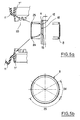
- Figure 4 is a section of another material embodiment of the thin wall (8), ensuring the decoupling function of rigidity.
- the thin wall (8) is produced without reinforcement in an elastomer membrane of the least acceptable weight. It rests, in radial deformation in the direction of the axis, on the circular grooves (18) formed, in this variant, directly in the solid ring (4).
- Said massive ring (4) has a single outer diameter, on which are fitted two internal half-rings (7 ′), rigid, identical in appearance, the material of which is intimately linked to the side walls (11), carries a comb (20 ), teeth parallel to the generators.
- the stop effect should start to be felt beyond 0.1 mm of offset. Indeed, so that, in the desired frequency ranges, a significant damping, of tangent ⁇ greater than 1, occurs, it is necessary that the deflections of the thin wall (8) are rigidly limited. As a result, an alternative pressure differential may appear between the opposite chambers which forces the resonant column to move. The amplitudes would theoretically be in the ratio of its section to that of a fictitious equivalent piston, which would transfer the liquid from one chamber to the other under the effect of the offset. The deformability of the side walls (11) is parasitic in this movement, which explains why the resonance of the equivalent mass-spring system is not as precise and limited in frequency as that of a solid-spring system.
- the complex shape of the side walls (11) and the thickness of the partition walls which are an integral part of it are chosen to satisfy the transverse and axial rigidities along the directions F2 and F3 of FIG. 1, determined by specifications.
- Figure 5 consists of an axial section 5a of the thin wall (8), including the exploded solids between which it is enclosed, and a view 5b, in elevation.
- the true thin wall (8) consists of two parts (23) which form a rectangular window, at the top and bottom, surrounded by the thickeners (24), on two diametrically opposite zones of the circumference. Thanks to said extra thicknesses (24), the thin wall (8) seals between the upper and lower chambers, by clamping between the solid ring (4), which is inside it, and the internal half-rings (7 ′) which come to enclose it.
- each of the parts (23) has beads (25), of shapes combined with those of the annular grooves (16), in which the lateral sealing takes place, under the effect of the fitting of the internal half-rings (7 ′), as shown in the exploded view.
- the method of manufacturing an elastic sleeve according to the invention does not modify the techniques usually used by the rubber maker.
- the two half-rings made up of the side walls (11), each integrating half of the two partition walls (12), are produced by a molding ensuring simultaneously the vulcanization of the elastomeric composition and the intimate connection, by adhering to the rigid elements.
- Each is, therefore, secured to an outer half-ring (9) and an internal half-ring (7) made of steel tube, or else (7 ′) of aluminum alloy or of thermoplastic or thermosetting materials, optionally reinforced with short fibers, such as, by way of nonlimiting example, glass fiber.
- the thin wall (8) is produced by a molding independent of the elastomeric composition, possibly reinforced by a layer of textile cables which can, by way of nonlimiting example, be laid by winding on an internal core.
- the positioning of the thin wall (8) is done by successive fitting, with the press of an internal half-ring (7) or (7 ′) equipped, as described, with said side walls (11), on the ring solid (4), enclosing the thin wall (8) between the annular groove (16) and the intermediate sleeve (17) or the internal half-rings (7 ′).
- the internal fixing ring (6) is thus produced to become a single solid.
- the two outer half-rings (9), thus elastically connected to this solid, by means of the side walls (11) are then fitted, in a sealed manner, into the round external fixing frame (1) provided with its ears. fixing (2) and (3).
- the filling with damping liquid, a mixture of water and antifreeze suitable for the use, is carried out by evacuation by means of a hole drilled in said round external fixing frame (1), followed by the introduction of liquid and closing said hole with a tight rivet (22).
- the production technique therefore offers manufacturers a particularly economical compromise in order to satisfy the contradictory conditions imposed on elastic supports for powertrains or similar needs.
Landscapes
- Engineering & Computer Science (AREA)
- General Engineering & Computer Science (AREA)
- Mechanical Engineering (AREA)
- Combined Devices Of Dampers And Springs (AREA)
- Vehicle Body Suspensions (AREA)
- Fluid-Damping Devices (AREA)
- Springs (AREA)
Priority Applications (1)
| Application Number | Priority Date | Filing Date | Title |
|---|---|---|---|
| AT90400954T ATE94624T1 (de) | 1989-04-10 | 1990-04-09 | Elastische, hydraulisch gedaempfte buchse mit radialer elastizitaet und entkoppelung der steifigkeiten. |
Applications Claiming Priority (2)
| Application Number | Priority Date | Filing Date | Title |
|---|---|---|---|
| FR8904790 | 1989-04-10 | ||
| FR8904790A FR2645609B1 (fr) | 1989-04-10 | 1989-04-10 | Manchon elastique a amortissement hydraulique de l'elasticite radiale et decouplage en rigidite |
Publications (2)
| Publication Number | Publication Date |
|---|---|
| EP0392909A1 true EP0392909A1 (de) | 1990-10-17 |
| EP0392909B1 EP0392909B1 (de) | 1993-09-15 |
Family
ID=9380615
Family Applications (1)
| Application Number | Title | Priority Date | Filing Date |
|---|---|---|---|
| EP90400954A Expired - Lifetime EP0392909B1 (de) | 1989-04-10 | 1990-04-09 | Elastische, hydraulisch gedämpfte Buchse mit radialer Elastizität und Entkoppelung der Steifigkeiten |
Country Status (11)
| Country | Link |
|---|---|
| US (1) | US5080331A (de) |
| EP (1) | EP0392909B1 (de) |
| JP (1) | JP2927869B2 (de) |
| KR (1) | KR900016648A (de) |
| AT (1) | ATE94624T1 (de) |
| BR (1) | BR9001624A (de) |
| CA (1) | CA2011535A1 (de) |
| DE (2) | DE392909T1 (de) |
| ES (1) | ES2020167T3 (de) |
| FR (1) | FR2645609B1 (de) |
| GR (1) | GR910300054T1 (de) |
Cited By (2)
| Publication number | Priority date | Publication date | Assignee | Title |
|---|---|---|---|---|
| DE4137692C1 (en) * | 1991-11-15 | 1993-07-01 | Mercedes-Benz Aktiengesellschaft, 7000 Stuttgart, De | Hydraulically damping support mounting with outer and inner portions - has wall part sealing bead between two chambers filled with damping medium. |
| EP0641955A1 (de) * | 1993-09-03 | 1995-03-08 | Tokai Rubber Industries, Ltd. | Elastisches, zylindrisches Lager, das eine hochviskose Flüssigkeit enthält und einen Einlass zum Einspritzen dieser Flüssigkeit hat |
Families Citing this family (9)
| Publication number | Priority date | Publication date | Assignee | Title |
|---|---|---|---|---|
| US5402980A (en) * | 1992-07-28 | 1995-04-04 | Champion International Corporation | Wound paper roll support apparatus |
| JP2000074131A (ja) * | 1998-08-26 | 2000-03-07 | Honda Motor Co Ltd | 液体封入防振装置 |
| US6216833B1 (en) * | 1999-07-22 | 2001-04-17 | Bridgestone/Firestone, Inc. | Vibration damper and method of making same |
| KR100489110B1 (ko) | 2002-03-25 | 2005-05-12 | 현대자동차주식회사 | 자동차의 엔진 마운팅 구조 |
| US7753349B1 (en) * | 2009-04-14 | 2010-07-13 | Miner Elastomer Products Corporation | Radial cushioning apparatus |
| DE102009041549B4 (de) * | 2009-09-15 | 2016-06-23 | Trelleborg Automotive Germany Gmbh | Elastische Buchse, insbesondere Verbundlenker-Buchse |
| CN102734374B (zh) * | 2012-06-28 | 2014-07-02 | 宁波拓普集团股份有限公司 | 新型液压衬套悬置 |
| US8882089B2 (en) | 2012-08-17 | 2014-11-11 | Itt Manufacturing Enterprises Llc | Dual radius isolator |
| CN111706639B (zh) * | 2020-05-27 | 2022-03-29 | 株洲时代新材料科技股份有限公司 | 一种液压复合衬套、用于其的流道及流道的形成方法 |
Citations (4)
| Publication number | Priority date | Publication date | Assignee | Title |
|---|---|---|---|---|
| EP0119796A2 (de) * | 1983-03-09 | 1984-09-26 | Bridgestone Tire Company Limited | Schwingungsdämpfungsvorrichtung |
| EP0278801A1 (de) * | 1987-01-23 | 1988-08-17 | Caoutchouc Manufacture Et Plastiques | Schwingungsdämpfungsvorrichtung mit hydraulischer Dämpfung der radialen Elastizität und Verfahren zur Herstellung einer derartigen Vorrichtung |
| EP0304349A1 (de) * | 1987-07-21 | 1989-02-22 | Automobiles Peugeot | Hydraulisch dämpfende Verbindung, insbesondere für die Motoraufhängung eines Kraftfahrzeugs |
| EP0306369A1 (de) * | 1987-08-04 | 1989-03-08 | Hutchinson | Hydraulisch gedämpfte Lagerbuchsen |
Family Cites Families (22)
| Publication number | Priority date | Publication date | Assignee | Title |
|---|---|---|---|---|
| FR2467724A1 (fr) * | 1979-10-22 | 1981-04-30 | Peugeot | Cale elastique, notamment pour la suspension d'un moteur de vehicule |
| DE3019337C2 (de) * | 1980-05-21 | 1986-07-31 | Fa. Carl Freudenberg, 6940 Weinheim | Elastisches Gummilager |
| FR2511105B1 (fr) * | 1981-08-07 | 1986-09-19 | Peugeot | Cale elastique, notamment pour la suspension d'un moteur de vehicule |
| EP0115417B1 (de) * | 1983-01-25 | 1989-04-19 | Avon Industrial Polymers Limited | Hydraulisch gedämpfte Lagerungsvorrichtung |
| JPS6049147A (ja) * | 1983-08-27 | 1985-03-18 | Tokai Rubber Ind Ltd | 流体入りブッシュ |
| FR2555273A1 (fr) * | 1983-11-22 | 1985-05-24 | Hutchinson Sa | Perfectionnements apportes aux supports antivibratoires hydrauliques |
| DE3402715A1 (de) * | 1984-01-26 | 1985-08-01 | Metzeler Kautschuk GmbH, 8000 München | Zweikammer-motorlager mit hydraulischer daempfung |
| DE3407553A1 (de) * | 1984-03-01 | 1985-09-05 | Continental Gummi-Werke Ag, 3000 Hannover | Hydraulisch gedaempftes elastisches lager insbesondere fuer den antriebsmotor in kraftfahrzeugen |
| FR2575253B1 (fr) * | 1984-12-24 | 1989-08-18 | Hutchinson | Support antivibratoire hydraulique |
| JPS629043A (ja) * | 1985-07-05 | 1987-01-17 | Toyota Motor Corp | 防振ゴム装置 |
| DE3531182A1 (de) * | 1985-08-31 | 1987-03-12 | Porsche Ag | Hydraulisch daempfendes lager |
| JPS62118133A (ja) * | 1985-11-18 | 1987-05-29 | Bridgestone Corp | 液入り防振装置 |
| FR2596123B1 (fr) * | 1986-03-19 | 1988-06-24 | Hutchinson Sa | Perfectionnements aux manchons de support antivibratoires hydrauliques |
| DE3617813A1 (de) * | 1986-05-27 | 1987-12-03 | Freudenberg Carl Fa | Motorlager |
| DE3617812A1 (de) * | 1986-05-27 | 1987-12-03 | Freudenberg Carl Fa | Motorlager |
| FR2599450B1 (fr) * | 1986-06-03 | 1990-08-10 | Hutchinson | Perfectionnements apportes aux manchons de support antivibratoires hydrauliques |
| JPH0430442Y2 (de) * | 1986-06-30 | 1992-07-22 | ||
| JPS636248U (de) * | 1986-06-30 | 1988-01-16 | ||
| JPS63145837A (ja) * | 1986-07-04 | 1988-06-17 | Tokai Rubber Ind Ltd | 円筒型流体封入式防振支持体 |
| FR2609515B1 (fr) * | 1987-01-14 | 1991-07-12 | Caoutchouc Manuf Plastique | Dispositif elastique d'isolation antivibratoire a amortissement hydraulique integre et butees de limitation de debattements internes |
| FR2613445B1 (fr) * | 1987-04-03 | 1991-07-05 | Caoutchouc Manuf Plastique | Support elastique a amortissement hydraulique integre avec cloison rigide a circuit de liquide ajustable |
| JPH01250637A (ja) * | 1988-03-31 | 1989-10-05 | Nissan Motor Co Ltd | 粘度可変流体封入制御型防振体 |
-
1989
- 1989-04-10 FR FR8904790A patent/FR2645609B1/fr not_active Expired - Fee Related
-
1990
- 1990-03-06 CA CA002011535A patent/CA2011535A1/fr not_active Abandoned
- 1990-03-15 KR KR1019900003499A patent/KR900016648A/ko not_active Ceased
- 1990-03-20 JP JP2071738A patent/JP2927869B2/ja not_active Expired - Lifetime
- 1990-04-06 BR BR909001624A patent/BR9001624A/pt not_active IP Right Cessation
- 1990-04-09 DE DE199090400954T patent/DE392909T1/de active Pending
- 1990-04-09 ES ES90400954T patent/ES2020167T3/es not_active Expired - Lifetime
- 1990-04-09 US US07/506,331 patent/US5080331A/en not_active Expired - Lifetime
- 1990-04-09 EP EP90400954A patent/EP0392909B1/de not_active Expired - Lifetime
- 1990-04-09 AT AT90400954T patent/ATE94624T1/de not_active IP Right Cessation
- 1990-04-09 DE DE90400954T patent/DE69003293T2/de not_active Expired - Fee Related
-
1991
- 1991-12-10 GR GR91300054T patent/GR910300054T1/el unknown
Patent Citations (4)
| Publication number | Priority date | Publication date | Assignee | Title |
|---|---|---|---|---|
| EP0119796A2 (de) * | 1983-03-09 | 1984-09-26 | Bridgestone Tire Company Limited | Schwingungsdämpfungsvorrichtung |
| EP0278801A1 (de) * | 1987-01-23 | 1988-08-17 | Caoutchouc Manufacture Et Plastiques | Schwingungsdämpfungsvorrichtung mit hydraulischer Dämpfung der radialen Elastizität und Verfahren zur Herstellung einer derartigen Vorrichtung |
| EP0304349A1 (de) * | 1987-07-21 | 1989-02-22 | Automobiles Peugeot | Hydraulisch dämpfende Verbindung, insbesondere für die Motoraufhängung eines Kraftfahrzeugs |
| EP0306369A1 (de) * | 1987-08-04 | 1989-03-08 | Hutchinson | Hydraulisch gedämpfte Lagerbuchsen |
Cited By (3)
| Publication number | Priority date | Publication date | Assignee | Title |
|---|---|---|---|---|
| DE4137692C1 (en) * | 1991-11-15 | 1993-07-01 | Mercedes-Benz Aktiengesellschaft, 7000 Stuttgart, De | Hydraulically damping support mounting with outer and inner portions - has wall part sealing bead between two chambers filled with damping medium. |
| EP0641955A1 (de) * | 1993-09-03 | 1995-03-08 | Tokai Rubber Industries, Ltd. | Elastisches, zylindrisches Lager, das eine hochviskose Flüssigkeit enthält und einen Einlass zum Einspritzen dieser Flüssigkeit hat |
| US5489086A (en) * | 1993-09-03 | 1996-02-06 | Tokai Rubber Industries, Ltd. | Cylindrical elastic mount containing highly viscous fluid and having fluid injecting inlet |
Also Published As
| Publication number | Publication date |
|---|---|
| KR900016648A (ko) | 1990-11-14 |
| DE69003293D1 (de) | 1993-10-21 |
| ES2020167A4 (es) | 1991-08-01 |
| JP2927869B2 (ja) | 1999-07-28 |
| DE392909T1 (de) | 1991-06-13 |
| GR910300054T1 (en) | 1991-12-10 |
| ATE94624T1 (de) | 1993-10-15 |
| ES2020167T3 (es) | 1994-01-01 |
| DE69003293T2 (de) | 1994-01-13 |
| BR9001624A (pt) | 1991-05-07 |
| FR2645609B1 (fr) | 1994-04-01 |
| CA2011535A1 (fr) | 1990-10-10 |
| EP0392909B1 (de) | 1993-09-15 |
| US5080331A (en) | 1992-01-14 |
| JPH02292542A (ja) | 1990-12-04 |
| FR2645609A1 (fr) | 1990-10-12 |
Similar Documents
| Publication | Publication Date | Title |
|---|---|---|
| EP0012638B1 (de) | Elastische Lagerung, insbesondere für die Aufhängung eines Fahrzeugmotors | |
| CA1310312C (fr) | Support elastique a amortissement hydraulique integre avec cloison rigidea circuit de liquide ajustable | |
| EP0156697B1 (de) | Änderungen an hydraulischen Antischwingungslagern | |
| EP0369847B1 (de) | Lager für eine drehende Welle | |
| EP0072262B1 (de) | Elastisches Lager, insbesondere für die Aufhängung eines Fahrzeugmotors | |
| EP0392909B1 (de) | Elastische, hydraulisch gedämpfte Buchse mit radialer Elastizität und Entkoppelung der Steifigkeiten | |
| EP0278801B1 (de) | Schwingungsdämpfungsvorrichtung mit hydraulischer Dämpfung der radialen Elastizität und Verfahren zur Herstellung einer derartigen Vorrichtung | |
| EP0490724A1 (de) | Hydroelastische Aufhängungsverbindung und mit dieser Befestigung verbundenes elastisches Bindeglied | |
| EP1179688B1 (de) | Hydraulisches, schwingungsisolierendes Buchsenlager | |
| FR2601098A1 (fr) | Structure de manchonnage elastique a remplissage de fluide | |
| FR2461165A1 (fr) | Monture d'amortissement de chocs | |
| WO2003033936A1 (fr) | Articulation hydroelastique rotulee | |
| EP0207958B1 (de) | Hydraulisches antischwingungslager | |
| EP0287455B1 (de) | Hydroelastisches Lager, insbesondere für Aufhängung eines Fahrzeugmotors | |
| EP0490747B1 (de) | Verbesserungen bei hydraulischen Antischwingungsvorrichtungen | |
| EP0225227A1 (de) | Änderungen an hydraulischen Anti-Schwingungslagern | |
| FR2973463A1 (fr) | Dispositif d'amortissement de vibration rempli de fluide du type a amortissement de vibration multidirectionnel | |
| EP1645773B1 (de) | Hydraulisches schwingungsdämpfendes Lager für ein Kraftfahrzeug und Herstellungsverfahren einer solchen Vorrichtung | |
| EP1447591A1 (de) | Hydraulisches schwingungsdämpfendes Lager | |
| EP0429362A1 (de) | Verbesserungen an hydraulischen, schwingungsdämpfenden, elastischen Lagern | |
| FR2702021A1 (fr) | Support hydroélastique modulaire. | |
| FR2714947A1 (fr) | Perfectionnements aux dispositifs antivibratoires hydrauliques. | |
| EP3742018B1 (de) | Hydraulisches schwingungsdämpfendes lager | |
| FR2876430A1 (fr) | Dispositif anti-vibratoire hydraulique et son procede de fabrication | |
| EP1089010B1 (de) | Kombiniertes Trennwand-Ventil- Element für hydroelastisches Lager |
Legal Events
| Date | Code | Title | Description |
|---|---|---|---|
| PUAI | Public reference made under article 153(3) epc to a published international application that has entered the european phase |
Free format text: ORIGINAL CODE: 0009012 |
|
| AK | Designated contracting states |
Kind code of ref document: A1 Designated state(s): AT BE CH DE ES FR GB GR IT LI LU NL SE |
|
| 17P | Request for examination filed |
Effective date: 19901112 |
|
| ITCL | It: translation for ep claims filed |
Representative=s name: JACOBACCI CASETTA & PERANI S.P.A. |
|
| GBC | Gb: translation of claims filed (gb section 78(7)/1977) | ||
| TCNL | Nl: translation of patent claims filed | ||
| DET | De: translation of patent claims | ||
| TCAT | At: translation of patent claims filed | ||
| 17Q | First examination report despatched |
Effective date: 19920520 |
|
| GRAA | (expected) grant |
Free format text: ORIGINAL CODE: 0009210 |
|
| AK | Designated contracting states |
Kind code of ref document: B1 Designated state(s): AT BE CH DE ES FR GB GR IT LI LU NL SE |
|
| PG25 | Lapsed in a contracting state [announced via postgrant information from national office to epo] |
Ref country code: GR Free format text: LAPSE BECAUSE OF FAILURE TO SUBMIT A TRANSLATION OF THE DESCRIPTION OR TO PAY THE FEE WITHIN THE PRESCRIBED TIME-LIMIT Effective date: 19930915 |
|
| REF | Corresponds to: |
Ref document number: 94624 Country of ref document: AT Date of ref document: 19931015 Kind code of ref document: T |
|
| ITF | It: translation for a ep patent filed | ||
| REF | Corresponds to: |
Ref document number: 69003293 Country of ref document: DE Date of ref document: 19931021 |
|
| GBT | Gb: translation of ep patent filed (gb section 77(6)(a)/1977) |
Effective date: 19930928 |
|
| REG | Reference to a national code |
Ref country code: GR Ref legal event code: FG4A Free format text: 3009055 |
|
| REG | Reference to a national code |
Ref country code: ES Ref legal event code: FG2A Ref document number: 2020167 Country of ref document: ES Kind code of ref document: T3 |
|
| PG25 | Lapsed in a contracting state [announced via postgrant information from national office to epo] |
Ref country code: AT Effective date: 19940409 |
|
| PG25 | Lapsed in a contracting state [announced via postgrant information from national office to epo] |
Ref country code: LI Effective date: 19940430 Ref country code: CH Effective date: 19940430 Ref country code: LU Free format text: LAPSE BECAUSE OF NON-PAYMENT OF DUE FEES Effective date: 19940430 Ref country code: BE Effective date: 19940430 |
|
| PLBE | No opposition filed within time limit |
Free format text: ORIGINAL CODE: 0009261 |
|
| STAA | Information on the status of an ep patent application or granted ep patent |
Free format text: STATUS: NO OPPOSITION FILED WITHIN TIME LIMIT |
|
| 26N | No opposition filed | ||
| BERE | Be: lapsed |
Owner name: CAOUTCHOUC MANUFACTURE ET PLASTIQUES Effective date: 19940430 |
|
| PG25 | Lapsed in a contracting state [announced via postgrant information from national office to epo] |
Ref country code: NL Effective date: 19941101 |
|
| NLV4 | Nl: lapsed or anulled due to non-payment of the annual fee | ||
| REG | Reference to a national code |
Ref country code: CH Ref legal event code: PL |
|
| EAL | Se: european patent in force in sweden |
Ref document number: 90400954.5 |
|
| REG | Reference to a national code |
Ref country code: FR Ref legal event code: ST |
|
| REG | Reference to a national code |
Ref country code: GR Ref legal event code: MM2A Free format text: 3009055 |
|
| REG | Reference to a national code |
Ref country code: FR Ref legal event code: RN |
|
| REG | Reference to a national code |
Ref country code: FR Ref legal event code: FC |
|
| PGFP | Annual fee paid to national office [announced via postgrant information from national office to epo] |
Ref country code: SE Payment date: 19990413 Year of fee payment: 10 |
|
| PGFP | Annual fee paid to national office [announced via postgrant information from national office to epo] |
Ref country code: ES Payment date: 19990416 Year of fee payment: 10 |
|
| PG25 | Lapsed in a contracting state [announced via postgrant information from national office to epo] |
Ref country code: SE Free format text: LAPSE BECAUSE OF NON-PAYMENT OF DUE FEES Effective date: 20000410 Ref country code: ES Free format text: THE PATENT HAS BEEN ANNULLED BY A DECISION OF A NATIONAL AUTHORITY Effective date: 20000410 |
|
| EUG | Se: european patent has lapsed |
Ref document number: 90400954.5 |
|
| REG | Reference to a national code |
Ref country code: GB Ref legal event code: IF02 |
|
| REG | Reference to a national code |
Ref country code: ES Ref legal event code: FD2A Effective date: 20020204 |
|
| PGFP | Annual fee paid to national office [announced via postgrant information from national office to epo] |
Ref country code: DE Payment date: 20080418 Year of fee payment: 19 |
|
| PGFP | Annual fee paid to national office [announced via postgrant information from national office to epo] |
Ref country code: IT Payment date: 20080426 Year of fee payment: 19 |
|
| PGFP | Annual fee paid to national office [announced via postgrant information from national office to epo] |
Ref country code: FR Payment date: 20080412 Year of fee payment: 19 |
|
| PGFP | Annual fee paid to national office [announced via postgrant information from national office to epo] |
Ref country code: GB Payment date: 20080421 Year of fee payment: 19 |
|
| GBPC | Gb: european patent ceased through non-payment of renewal fee |
Effective date: 20090409 |
|
| PG25 | Lapsed in a contracting state [announced via postgrant information from national office to epo] |
Ref country code: DE Free format text: LAPSE BECAUSE OF NON-PAYMENT OF DUE FEES Effective date: 20091103 |
|
| PG25 | Lapsed in a contracting state [announced via postgrant information from national office to epo] |
Ref country code: GB Free format text: LAPSE BECAUSE OF NON-PAYMENT OF DUE FEES Effective date: 20090409 |
|
| REG | Reference to a national code |
Ref country code: FR Ref legal event code: ST Effective date: 20101130 |
|
| PG25 | Lapsed in a contracting state [announced via postgrant information from national office to epo] |
Ref country code: IT Free format text: LAPSE BECAUSE OF NON-PAYMENT OF DUE FEES Effective date: 20090409 |
|
| PG25 | Lapsed in a contracting state [announced via postgrant information from national office to epo] |
Ref country code: FR Free format text: LAPSE BECAUSE OF NON-PAYMENT OF DUE FEES Effective date: 20090430 |