EP0393207A1 - Verfahren und gerät zur speicherung - Google Patents
Verfahren und gerät zur speicherung Download PDFInfo
- Publication number
- EP0393207A1 EP0393207A1 EP89911399A EP89911399A EP0393207A1 EP 0393207 A1 EP0393207 A1 EP 0393207A1 EP 89911399 A EP89911399 A EP 89911399A EP 89911399 A EP89911399 A EP 89911399A EP 0393207 A1 EP0393207 A1 EP 0393207A1
- Authority
- EP
- European Patent Office
- Prior art keywords
- data
- signals
- track
- divided
- tracks
- Prior art date
- Legal status (The legal status is an assumption and is not a legal conclusion. Google has not performed a legal analysis and makes no representation as to the accuracy of the status listed.)
- Granted
Links
Images







Classifications
-
- G—PHYSICS
- G11—INFORMATION STORAGE
- G11B—INFORMATION STORAGE BASED ON RELATIVE MOVEMENT BETWEEN RECORD CARRIER AND TRANSDUCER
- G11B20/00—Signal processing not specific to the method of recording or reproducing; Circuits therefor
- G11B20/10—Digital recording or reproducing
- G11B20/12—Formatting, e.g. arrangement of data block or words on the record carriers
-
- G—PHYSICS
- G11—INFORMATION STORAGE
- G11B—INFORMATION STORAGE BASED ON RELATIVE MOVEMENT BETWEEN RECORD CARRIER AND TRANSDUCER
- G11B20/00—Signal processing not specific to the method of recording or reproducing; Circuits therefor
- G11B20/10—Digital recording or reproducing
-
- G—PHYSICS
- G11—INFORMATION STORAGE
- G11B—INFORMATION STORAGE BASED ON RELATIVE MOVEMENT BETWEEN RECORD CARRIER AND TRANSDUCER
- G11B20/00—Signal processing not specific to the method of recording or reproducing; Circuits therefor
- G11B20/10—Digital recording or reproducing
- G11B20/12—Formatting, e.g. arrangement of data block or words on the record carriers
- G11B20/1201—Formatting, e.g. arrangement of data block or words on the record carriers on tapes
- G11B20/1207—Formatting, e.g. arrangement of data block or words on the record carriers on tapes with transverse tracks only
- G11B20/1208—Formatting, e.g. arrangement of data block or words on the record carriers on tapes with transverse tracks only for continuous data, e.g. digitised analog information signals, pulse code modulated [PCM] data
-
- G—PHYSICS
- G11—INFORMATION STORAGE
- G11B—INFORMATION STORAGE BASED ON RELATIVE MOVEMENT BETWEEN RECORD CARRIER AND TRANSDUCER
- G11B27/00—Editing; Indexing; Addressing; Timing or synchronising; Monitoring; Measuring tape travel
- G11B27/02—Editing, e.g. varying the order of information signals recorded on, or reproduced from, record carriers
- G11B27/031—Electronic editing of digitised analogue information signals, e.g. audio or video signals
- G11B27/032—Electronic editing of digitised analogue information signals, e.g. audio or video signals on tapes
-
- G—PHYSICS
- G11—INFORMATION STORAGE
- G11B—INFORMATION STORAGE BASED ON RELATIVE MOVEMENT BETWEEN RECORD CARRIER AND TRANSDUCER
- G11B27/00—Editing; Indexing; Addressing; Timing or synchronising; Monitoring; Measuring tape travel
- G11B27/02—Editing, e.g. varying the order of information signals recorded on, or reproduced from, record carriers
- G11B27/031—Electronic editing of digitised analogue information signals, e.g. audio or video signals
- G11B27/036—Insert-editing
-
- G—PHYSICS
- G11—INFORMATION STORAGE
- G11B—INFORMATION STORAGE BASED ON RELATIVE MOVEMENT BETWEEN RECORD CARRIER AND TRANSDUCER
- G11B20/00—Signal processing not specific to the method of recording or reproducing; Circuits therefor
- G11B20/10—Digital recording or reproducing
- G11B20/10527—Audio or video recording; Data buffering arrangements
- G11B2020/10537—Audio or video recording
- G11B2020/10592—Audio or video recording specifically adapted for recording or reproducing multichannel signals
-
- G—PHYSICS
- G11—INFORMATION STORAGE
- G11B—INFORMATION STORAGE BASED ON RELATIVE MOVEMENT BETWEEN RECORD CARRIER AND TRANSDUCER
- G11B2220/00—Record carriers by type
- G11B2220/20—Disc-shaped record carriers
- G11B2220/21—Disc-shaped record carriers characterised in that the disc is of read-only, rewritable, or recordable type
- G11B2220/215—Recordable discs
- G11B2220/216—Rewritable discs
-
- G—PHYSICS
- G11—INFORMATION STORAGE
- G11B—INFORMATION STORAGE BASED ON RELATIVE MOVEMENT BETWEEN RECORD CARRIER AND TRANSDUCER
- G11B2220/00—Record carriers by type
- G11B2220/90—Tape-like record carriers
Definitions
- the present invention relates, in a record reproducing apparatus for video, cassette, recorder or the like, to a method of allocating into a plurality of data tracks the recording signals (for example, audio signals and video signals) composed of a plurality of editing unit data so as to record them.
- the recording signals for example, audio signals and video signals
- a recording method is general which allocates the recording signals into a plurality of data tracks so as to effect the recording operation on a recording medium the recording signals (for example, audio signals and video signals) composed of a plurality of editing unit data.
- the recording signals for example, audio signals and video signals
- the recording signals composed of a plurality of editing unit data.
- the data in one editing unit of the recording signal is defined to be the data in the least unit to be capable of rewriting operation in the recording of the new signals on the prerecorded part on the recording medium by a certain record reproducing apparatus.
- the recording signals are video signals
- the data in the editing unit become the data of the video signals of one field or one frame.
- a recording method is provided of allocating the data of a certain one editing unit as it is on one data track on the recording medium without dividing the data in a certain one edition unit into a plurality of them so as to effect the recording operation.
- Fig. 10 is a format chart on the recording medium in the conventional recording method.
- a recording method of allocating into two data tracks four editing units of data (the audio signals of four channels) is simply described, with the format of the other portions being not mentioned.
- the data (audio signals of four channels) "Al”, “Bl”, “Cl”, “Dl” of four editing units are allocated to the portions of 101, 102, 103, 104 of two data tacks. Namely, the data (the audio signal of one channel) of one editing unit are allocated to one data track without being divided.
- Fig. 11 is a model chart showing how the reproduction signals are being deteriorated in the editing point to be caused when the linearity of the track has been shifted.
- Fig. 11 A shows a record pattern chart with the audio signals of four channels being recorded in the time series in accordance with the format shown in Fig. 10.
- the same drawing B is a record pattern chart in a case where the linearity of the track has been shifted by Xl in the track pitch direction with comparison with the record pattern shown in the same drawing A, with the insertion edition to the editing point (editing unit data "A2") about the editing unit data "Al” through "A4" of the audio signal of one channel of the audio signals of four channels shown in the same drawing A.
- the same drawing C is a record pattern chart with the linearity of the track being shifted by X2 in an inverse direction to the record pattern shown in the same drawing B as compared with the record pattern of the same drawing A, with the connecting record being performed from the editing unit data "A3" about the record pattern recorded as in the same drawing B.
- An object of the present invention is to provide a recording method of reducing the deterioration of the reproduction signals at the editing point as compared with the conventional recording method even when the editing operation is effected with the track being shifted from the already recorded track pattern because of the track linearity shift, the head height shift by the mechanical precision problems, further the tracking shift during the reproducing operation, and so on.
- the recording method of the present invention comprises a step of dividing the data of the respective editing units of the recording signals into the data of N number (N is an integer of two or more) with the individual portions divided being provided as the partial data tracks, and a step of allocating the respective divided data into the N number of partial data tracks adjacent among the data tracks so as to effect the recording operation on the recording medium, with all the data tracks being divided into a plurality, the individual portions divided being provided as the partial data tracks.
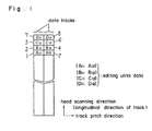
- Fig. 1 is a format chart on the recording medium recorded by the recoding method in the first embodiment of the present invention.
- N 2 in the dividing operation of one editing unit into a N number (N is an integer of two or more)
- the region where the data of one editing unit is occupied in the recording medium is distributed narrowly in the head scanning direction and widely in the track pitch direction as compared with the conventional example.
- the data of the editing unit in the other data track which are not shown in Fig. 1 is also allocated and recorded on the recording medium in the similar method.
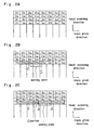
- Fig. 2 A through C are model charts showing the deterioration of the reproduction signals at the editing point to be caused in a case when the linearity of the track has been shifted in the the interchangeable reproduction by the recording method in the first embodiment of the present invention.
- the same drawing A shows the record pattern chart recorded in accordance with the recording method in the first embodiment of the present invention, the inserting edition is effected up to the editing points ("A21, A22") about the "All, A12", “A21, A22” through “A41, A42", “B11, B12", “B21, B22” through “B41, B42", “Cll, C12", “C21, C22” through “C41, C42", “D11, D12", “D21, D22” through “D41, d42” shown in the same drawing A, the same drawing B shows the recording pattern when the linearity of the track has been shifted by
- the same drawing C is a record pattern chart when the linearity of the track has been inversely shifted by X2 to the record pattern shown in the same drawing B through comparison with the record pattern of the same drawing A, with the connection record being effected after the editing point in the record pattern recorded like the same drawing B, namely, in the "A31, A32" and "A41, A42".
- the divided editing unit data are necessarily recorded and reproduced by the recording and reproducing apparatus having the same editing unit data, so that there is no possibility of receiving the interferences of the overlapped writing and the unerased remains between two adjacent data tracks (for example, between the division data "All, A12" in Fig. 2 C) with one editing unit of data being divided and being allocated thereinto.
- the region occupied by one editing unit data is distributed so as to be narrow in the head scanning direction and wide in the track pitch direction as compared with the conventional arrangement, the region to be affected upon deterioration of the track linearity during exchanging reproduction is consequently reduced.
- Fig. 3 is a format on the recording medium recorded by the recording method in the second embodiment of the present invention.
- the data (not shown) of the editing unit of the audio signals of four channels and the video signals are inputted as the "Al”, “A2" through “A6", the "Bl”, the “B2” through “B6", the "Cl”, the “C2” through “C6", the "D1", “D2” through “D6", the "V1", "V2” respectively in the time series order, and are to be recorded after having been divided.
- the data of the editing unit of the audio signal of four channels are respectively divided into two of "All, A12", the “A21, A22” through “A61, A62", the B11, B12", the “B21, B22” through the “B61, B62", the “Cll, C12", the “C21, C22” through “C61, C62", the "D11, D12", the “D21. D22” through “D61, D62” as in the first embodiment, also, the editing unit data "Vl", "V2" of the video signal are divided respectively into six of the "Vll, through V16", the "V21, through V26".
- each data of the audio signals of four channels are allocated, recorded onto the pairs (301, 302), (315, 316), (319, 320), (329, 330), (333, 324), (347, 348), and (303, 304), (313, 314), (317, 318), (331, 332), (335, 336), (345, 346), and (305, 306), (311, 312), (323, 324), (325, 326), (337, 338), (343, 344), and (307),308), (309, 310), (321, 322), (327, 328), (339, 340), (341, 342) of the adjacent two partial data tracks between the data tracks, and each data of the video signals are allocated, recorded onto the adjacent six partial data tracks (349 through 354) and (355 through 360) among the data tracks.
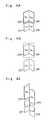
- FIG. 4 A through C there are shown patterns as to the way of arranging the partial data tracks 339, 340 with the data "D51", “D52” with the data "D5" of one editing unit being divided being allocated thereto.
- Fig. 4 A through C there is included only the data of one editing unit (in the same drawing, the editing unit data "D5").
- the present embodiment has, for example, one editing unit data "C5" divided into two, "C51", “C52” arranged in parallel contact into two tracks in the approximately vertical direction with respect to the head scanning direction, namely, the track pitch direction
- the data "C5" may be divided into three as in the "C51", “C52", “C53” (not shown) and be brought into parallel contact with the three tracks.
- the length of the head scanning direction of each division data may be made shorter as compared with the case of the two division, also the length of the track pitch direction becomes longer as compared with the two divisions, so that the deterioration of the reproduction signals caused by the track shift is reduced. Namely, as the number of the divisions becomes larger, the deterioration of the reproduction signals may be reduced.
- the order in which the respective signals are allocated is not restricted to it, so that the data of the editing unit of each signal may be divided, recorded so that the audio signals of four channels may be arranged continuously on the data track in the order of, for example, the audio signals of four channels, the video signal without the division into the respective two channels with the video signal being provided between the audio signals of four channels to effect the recording. Also, in this case, it is needless to say that the recording operation may be effected in the order of the video signal, and the audio signals of four channels.
- the video signal to be allocated originally into the one data track with one data track being provided as six partial data tracks is divided into two so as to divide the data of the editing unit of each signal in the order of the video signal, the audio signal of four channels, and the video signal so that they may be allocated, recorded onto six partial data tracks.
- Fig. 5 is a block diagram of the magnetic recording apparatus of the present invention, and the (1) through (11) are arranged to constitute one drawing with two.
- reference numeral 501 is a means for dividing the data of the editing unit into a plurality of data
- reference numeral 502 is a means for allocating each data divided to the partial data tracks so as to record them on the recording medium.
- Reference numerals 504, 505, 514 are circuits for processing various types of signals
- reference numerals 503, 506, 507, 508, 509 are split circuits
- reference numerals 510, 512, 516 are timing generating circuits
- reference numerals 511, 513 are change-over circuits
- reference numeral 515 is a rotary transformer
- reference numeral 517 is a cylinder
- reference numerals 518, 519 and 520, 521 are a pair of heads
- reference numerals 522 through 524 and reference numerals 529 through 532 are multiplexers (hereinafter referred to as MUX)
- reference numerals 525 through 528 are memories (hereinafter referred to as MEM)
- the apparatus of the present embodiment is composed of a means 501 for dividing the data (audio signals of four channels) "A1", “B1", “C1", “D1" of the four editing units inputted through the signal processing circuit 504 for correcting the errors, and so on respectively into two "All", “A12”, “Bll” through “D11”, “D12”, and a means 502 for allocating them into a plurality of partial data tracks adjacent among the data tracks so as to record them on the magnetic recording medium.
- the four editing units of data "Al”, “Bl” through “D1” inputted from the input terminals 540, 541, 542, 543 are inputted respectively into the split circuits 506 through 509 through the signal processing circuit 508.
- Each of the inputted data “A1”, “Bl” through “Dl” are divided into the data of the "All, A12", the "B11, B12” through “D11, D12” by the split circuits 506 through 509 with control signals to be obtained by the timing generating circuit 510 and are outputted into the change-over circuit 511.
- the "Vl" of the editing unit data of the video signals inputted from the input terminal 544 is inputted into the split circuit 503 through the signal processing circuit 504.
- the inputted data "V1" is divided to output the "V11", "V12" as the output data.
- the divided data "All", “A12”, “B11” through “D11”, “D12” and “V11”, “V12” are rearranged into the “All", “B11”, “V11”, “C11”, “D11” and “A12”, “B12”, “V12”, “C12”, “D12” in the time series order by the control signals to be obtained by the timing generating circuit 512 so as to output them respectively as the signals of CHO and CH1.
- the output signals CHO, CH1 outputted from the change-over circuit 511 are inputted into the change-over circuit 513 through the signal processing circuit 505 for effecting the digital/analog conversion and so on.
- the change-over circuit 513 is provided to record the signals CHO and CH1 on the recording medium bound on the cylinder 517 by the use of pair heads 518, 521 and pair heads 519, 520 mounted by 180 degrees in space on the cylinder 517.
- the signals CHO and CH1 are outputted with the control signals to be obtained by the timing generating circuit 516 with the switching operation being effected after a certain period into the pair heads 518, 519 and the pair heads 521, 520.
- Each of four output signals outputted by the change-over circuit 513 is sent to each head 518, 519, 520, 521 through a signal processing circuit 514 and a rotary transfer 515.
- the respective timing generating circuits 510, 512, 516 are adapted to output a control signal in accordance with an identifying signal (hereinafter referred as to ID signal) showing the type of the data to be outputted from the signal processing circuit 504 and the head switch (HSW).
- ID signal an identifying signal showing the type of the data to be outputted from the signal processing circuit 504 and the head switch (HSW).
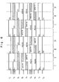
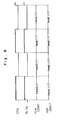
- Fig. 6 shows a control signal to be outputted from a timing generating circuit 510 in Fig. 5.
- Fig. 6 shows a digital control signal of high or low, with the oblique line portions showing that the signal may be high or low.
- Table 1 shows the operation modes of the MUX522, 523, 524, 529, 530 which are used in the split circuit 506 in Fig. 5. Namely, when the control signals to be inputted is high, the respective MUXs are switched onto the terminal side of the (a), (c), (e), (g), (i), when the control signal is low, the respective MUXs are switched onto the terminal side of the (b), (d), (f), (h), (j).
- Table 2 shows the operation modes of the MEM525 through 528 which are used in the split circuit 506 in Fig. 5. Namely, when the control signal to be inputted is high, each MEM becomes a storing (write) mode, and when it becomes low, each MEM becomes a reading (read) mode.
- Fig. 7 shows the condition of the operations of the respective MEM525 through 528 and the MUX522, 523, 524, 529, 530 by the control signals Tl through T9 in the periods of I, II, III, IV shown in Fig. 6.
- the MEM527, 528 are in the reading condition, and also, when the MEM525, 526 are in the reading condition, the MEM527, 528 are controlled to become the storing condition.
- the time series former half portion of one editing unit data "Al" of the inputted audio signal is controlled to be stored into the MEM525, MEM527, the time series latter half portion is controlled to be stored into the MEM 526, MEM528.
- the split circuits 507, 508, 509 are also composed of MUX, MEM and so on as in the split circuit 506 to effect the similar operations. Namely, the data "Bl”, “Cl”, “Dl” of the respective editing units inputted as in the split circuit 506 shown in Fig. 7 are divided into the data of the "B11” "B12", “C11” “C12”, “D11” "12” by the split circuits 507, 508, 509 in accordance with the control signal to be obtained by the timing generating circuit 510, and are outputted into the change-over circuit 511.
- Table 3 shows the operation modes of the MUX531 and MUX532 in the change-over circuit 511 of Fig. 5. Namely, in the MUX531 and MUX532, the respective terminals of the (k), (p) are adapted to be selected when the control signals T10, T11 to be inputted are 0, the respective terminals of the (1), (q) are adapted to be selected when the control signals to be inputted are one, the respective terminals of the (m), (r) are adapted to be selected when they are two, the respective terminals of the (n), (s) are adapted to be selected when they are three, the respective terminals of the (o), (t) are selected when they are four..
- Fig. 8 shows the change-over operation of the MUX531 and MUX532 by the control signals T10, T11 and the control signals T10, T11 to be obtained by the timing generating circuit 512 of Fig. 6, and the output signals of the MUX531 and the MUX532 to be obtained by the change-over operation.
- the data divided by the change-over circuit 511 is arranged in the time series order in accordance with the control signals T10, T11 to be obtained by the timing generating circuit 512 and are outputted respectively as the signals CHO, CH1.
- Table 4 shows the operation modes of the ASW533 and ASW534 of the change-over circuit 513 of Fig. 5.
- the terminals of the (u) and (w) are selected respectively, and when the control signal to be inputted is low, the terminals of the (v) and (x) are selected respectively.
- Fig. 9 shows how the ASW533 and the ASW534 are changed over by the control signals T12, T13 and the control signals T12, T13 to be obtained by the timing generating circuit 516 of Fig. 5.
- the change-over circuit 513 the signals CHO and CH1 are switched into the pair heads 518, 519 and the pair heads 521, 520 for each of the constant periods in accordance with the control signals T12, T13 to be obtained by the timing generating circuit 516, and may be outputted.
- the signals outputted from the change-over circuit 513 are fed respectively into the heads 518, 519, 520, 521 on the cylinder 517 through the signal processing circuit 514 for controlling the gain, the rotary transformer 515, and are recorded on the magnetic recording medium (not shown) by each head.
Landscapes
- Engineering & Computer Science (AREA)
- Signal Processing (AREA)
- Multimedia (AREA)
- Signal Processing For Digital Recording And Reproducing (AREA)
- Television Signal Processing For Recording (AREA)
- Management Or Editing Of Information On Record Carriers (AREA)
Applications Claiming Priority (3)
| Application Number | Priority Date | Filing Date | Title |
|---|---|---|---|
| JP257578/88 | 1988-10-13 | ||
| JP63257578A JP2553668B2 (ja) | 1988-10-13 | 1988-10-13 | 磁気記録方法 |
| PCT/JP1989/001058 WO1990004251A1 (fr) | 1988-10-13 | 1989-10-13 | Procede et appareil d'enregistrement |
Publications (3)
| Publication Number | Publication Date |
|---|---|
| EP0393207A1 true EP0393207A1 (de) | 1990-10-24 |
| EP0393207A4 EP0393207A4 (en) | 1993-03-03 |
| EP0393207B1 EP0393207B1 (de) | 1995-06-28 |
Family
ID=17308217
Family Applications (1)
| Application Number | Title | Priority Date | Filing Date |
|---|---|---|---|
| EP89911399A Expired - Lifetime EP0393207B1 (de) | 1988-10-13 | 1989-10-13 | Verfahren und gerät zur speicherung |
Country Status (6)
| Country | Link |
|---|---|
| US (1) | US5150262A (de) |
| EP (1) | EP0393207B1 (de) |
| JP (1) | JP2553668B2 (de) |
| KR (1) | KR0171406B1 (de) |
| DE (1) | DE68923267T2 (de) |
| WO (1) | WO1990004251A1 (de) |
Cited By (5)
| Publication number | Priority date | Publication date | Assignee | Title |
|---|---|---|---|---|
| EP0437316A1 (de) * | 1990-01-09 | 1991-07-17 | Matsushita Electric Industrial Co., Ltd. | Aufzeichnungsverfahren für digitale Signale und Gerät zur Aufzeichnung und Wiedergabe digitaler Signale |
| EP0467272A3 (en) * | 1990-07-16 | 1993-02-24 | Matsushita Electric Industrial Co., Ltd. | Video and audio signal recording/reproducing apparatus |
| EP0574238A1 (de) * | 1992-06-10 | 1993-12-15 | Matsushita Electric Industrial Co., Ltd. | Aufzeichnungs- und Wiedergabegerät für digitale Signale |
| EP0508779A3 (de) * | 1991-04-11 | 1994-02-16 | Matsushita Electric Industrial Co Ltd | |
| EP0831486A3 (de) * | 1996-09-24 | 1999-12-29 | Victor Company Of Japan, Ltd. | Informationsaufzeichnungs-/-wiedergabegerät und -methode |
Families Citing this family (11)
| Publication number | Priority date | Publication date | Assignee | Title |
|---|---|---|---|---|
| JP2969782B2 (ja) * | 1990-05-09 | 1999-11-02 | ソニー株式会社 | 符号化データ編集方法及び符号化データ編集装置 |
| US5272691A (en) * | 1991-05-30 | 1993-12-21 | Matsushita Electric Industrial Co., Ltd. | Method for recording and reproducing compressed data |
| US5274509A (en) * | 1992-09-10 | 1993-12-28 | Digital Equipment Corporation | On-the-fly splitting of disk data blocks using timed sampling of a data position indicator |
| EP0622956B1 (de) * | 1993-04-26 | 1999-03-03 | Matsushita Electric Industrial Co., Ltd. | Gerät zur Aufzeichnung von digitalen Video- und Audiosignalen |
| JPH09282849A (ja) * | 1996-04-08 | 1997-10-31 | Pioneer Electron Corp | 情報記録媒体並びにその記録装置及び再生装置 |
| US7085387B1 (en) * | 1996-11-20 | 2006-08-01 | Metcalf Randall B | Sound system and method for capturing and reproducing sounds originating from a plurality of sound sources |
| US6239348B1 (en) * | 1999-09-10 | 2001-05-29 | Randall B. Metcalf | Sound system and method for creating a sound event based on a modeled sound field |
| CA2499754A1 (en) * | 2002-09-30 | 2004-04-15 | Electro Products, Inc. | System and method for integral transference of acoustical events |
| WO2006050353A2 (en) * | 2004-10-28 | 2006-05-11 | Verax Technologies Inc. | A system and method for generating sound events |
| CA2598575A1 (en) * | 2005-02-22 | 2006-08-31 | Verax Technologies Inc. | System and method for formatting multimode sound content and metadata |
| US20100223552A1 (en) * | 2009-03-02 | 2010-09-02 | Metcalf Randall B | Playback Device For Generating Sound Events |
Family Cites Families (11)
| Publication number | Priority date | Publication date | Assignee | Title |
|---|---|---|---|---|
| JPS5656075A (en) * | 1979-09-21 | 1981-05-16 | Rca Corp | Tape format and system for recording and reproducing same |
| DE3340113A1 (de) * | 1983-11-05 | 1985-05-15 | Robert Bosch Gmbh, 7000 Stuttgart | System zur speicherung digital codierter signale auf magnetband |
| JPH07122966B2 (ja) * | 1984-03-19 | 1995-12-25 | 株式会社日立製作所 | 回転ヘッド型pcmレコーダの記録方法及び再生方法 |
| JPS6129454A (ja) * | 1984-07-20 | 1986-02-10 | Matsushita Electric Ind Co Ltd | デイジタル音声信号伝送方法 |
| GB2164479B (en) * | 1984-09-10 | 1988-09-07 | Sony Corp | Recording audio signals |
| JPS61148608A (ja) * | 1984-12-21 | 1986-07-07 | Mitsubishi Electric Corp | 磁気記録再生装置 |
| JPS61261874A (ja) * | 1985-05-15 | 1986-11-19 | Sony Corp | 記録再生装置 |
| US4761693A (en) * | 1986-02-19 | 1988-08-02 | Pioneer Electronic Corporation | Magnetic recording and reproducing device |
| JPS62234478A (ja) * | 1986-04-04 | 1987-10-14 | Matsushita Electric Ind Co Ltd | 映像信号の記録再生装置 |
| JP2576512B2 (ja) * | 1987-06-29 | 1997-01-29 | ソニー株式会社 | デ−タレコ−ダ |
| JPH06129454A (ja) * | 1992-01-21 | 1994-05-10 | Nisshinbo Ind Inc | 非石綿系摩擦材 |
-
1988
- 1988-10-13 JP JP63257578A patent/JP2553668B2/ja not_active Expired - Lifetime
-
1989
- 1989-10-13 DE DE68923267T patent/DE68923267T2/de not_active Expired - Fee Related
- 1989-10-13 EP EP89911399A patent/EP0393207B1/de not_active Expired - Lifetime
- 1989-10-13 KR KR1019900701258A patent/KR0171406B1/ko not_active Expired - Fee Related
- 1989-10-13 WO PCT/JP1989/001058 patent/WO1990004251A1/ja not_active Ceased
-
1990
- 1990-06-11 US US07/476,496 patent/US5150262A/en not_active Expired - Lifetime
Cited By (8)
| Publication number | Priority date | Publication date | Assignee | Title |
|---|---|---|---|---|
| EP0437316A1 (de) * | 1990-01-09 | 1991-07-17 | Matsushita Electric Industrial Co., Ltd. | Aufzeichnungsverfahren für digitale Signale und Gerät zur Aufzeichnung und Wiedergabe digitaler Signale |
| US5459621A (en) * | 1990-01-09 | 1995-10-17 | Matsushita Electric Industrial Co., Ltd. | Method and apparatus for rotary-head type signal recording and reproducing of digital video/audio signals |
| EP0467272A3 (en) * | 1990-07-16 | 1993-02-24 | Matsushita Electric Industrial Co., Ltd. | Video and audio signal recording/reproducing apparatus |
| US5457579A (en) * | 1990-07-16 | 1995-10-10 | Matsushita Electric Industrial Co., Ltd. | Apparatus for recording each editing unit of video and audio signals in an isolated area on a recording medium |
| EP0508779A3 (de) * | 1991-04-11 | 1994-02-16 | Matsushita Electric Industrial Co Ltd | |
| EP0574238A1 (de) * | 1992-06-10 | 1993-12-15 | Matsushita Electric Industrial Co., Ltd. | Aufzeichnungs- und Wiedergabegerät für digitale Signale |
| US5371604A (en) * | 1992-06-10 | 1994-12-06 | Matsushita Electric Industrial Co., Ltd. | Apparatus for edit recording of a compressed digital video signal on a recording tape |
| EP0831486A3 (de) * | 1996-09-24 | 1999-12-29 | Victor Company Of Japan, Ltd. | Informationsaufzeichnungs-/-wiedergabegerät und -methode |
Also Published As
| Publication number | Publication date |
|---|---|
| EP0393207B1 (de) | 1995-06-28 |
| JP2553668B2 (ja) | 1996-11-13 |
| JPH02105370A (ja) | 1990-04-17 |
| DE68923267D1 (de) | 1995-08-03 |
| WO1990004251A1 (fr) | 1990-04-19 |
| KR0171406B1 (ko) | 1999-04-15 |
| KR900702526A (ko) | 1990-12-07 |
| US5150262A (en) | 1992-09-22 |
| EP0393207A4 (en) | 1993-03-03 |
| DE68923267T2 (de) | 1996-02-15 |
Similar Documents
| Publication | Publication Date | Title |
|---|---|---|
| EP0393207B1 (de) | Verfahren und gerät zur speicherung | |
| EP0130091B1 (de) | Gerät zur Aufzeichnung und/oder Wiedergabe von digitalen Informationssignalen | |
| GB2092814A (en) | Magnetic recording and reproducing apparatus | |
| KR860001410A (ko) | 정지 헤드로서 디지탈 신호의 기록 및 재생을 위한 방법과 그 장치 | |
| EP0907257A2 (de) | Fehlerkorrektur verschachtelter Datenblöcke | |
| EP0335273A2 (de) | System zum Aufzeichnen und Wiedergeben von digitalen Audiosignalen | |
| KR950009383B1 (ko) | 디지틀음성신호기록방법 | |
| JPS6059646B2 (ja) | ビデオ信号の記録方法と記録装置 | |
| JPH0654587B2 (ja) | シャツフリング方法 | |
| US5809209A (en) | Video signal recording apparatus with varying interleaving of digital video signals | |
| US5459621A (en) | Method and apparatus for rotary-head type signal recording and reproducing of digital video/audio signals | |
| US4761693A (en) | Magnetic recording and reproducing device | |
| JPS6340077B2 (de) | ||
| KR100250235B1 (ko) | 데이터 기록방법 | |
| US5940575A (en) | Video signal recording apparatus | |
| KR960002151B1 (ko) | 영상 및 음성신호 기록재생장치 | |
| EP0622956B1 (de) | Gerät zur Aufzeichnung von digitalen Video- und Audiosignalen | |
| JP3592597B2 (ja) | エラー訂正装置及びプログラム記録媒体 | |
| JP3103565B2 (ja) | ビデオ信号処理方法 | |
| US5151831A (en) | Digital signal processing circuit | |
| JPH0750071A (ja) | デジタルデータ記録再生方法及び記録媒体 | |
| JPH0474365A (ja) | ディジタル記録方法 | |
| JPS6086983A (ja) | 磁気記録再生装置 | |
| JPS6320772A (ja) | 多チヤンネル型のデイジタル信号再生装置 | |
| JPH03185683A (ja) | ビデオ信号記録装置 |
Legal Events
| Date | Code | Title | Description |
|---|---|---|---|
| PUAI | Public reference made under article 153(3) epc to a published international application that has entered the european phase |
Free format text: ORIGINAL CODE: 0009012 |
|
| AK | Designated contracting states |
Kind code of ref document: A1 Designated state(s): DE FR GB NL |
|
| 17P | Request for examination filed |
Effective date: 19900919 |
|
| A4 | Supplementary search report drawn up and despatched |
Effective date: 19930111 |
|
| AK | Designated contracting states |
Kind code of ref document: A4 Designated state(s): DE FR GB NL |
|
| 17Q | First examination report despatched |
Effective date: 19931111 |
|
| GRAA | (expected) grant |
Free format text: ORIGINAL CODE: 0009210 |
|
| AK | Designated contracting states |
Kind code of ref document: B1 Designated state(s): DE FR GB NL |
|
| REF | Corresponds to: |
Ref document number: 68923267 Country of ref document: DE Date of ref document: 19950803 |
|
| ET | Fr: translation filed | ||
| PLBE | No opposition filed within time limit |
Free format text: ORIGINAL CODE: 0009261 |
|
| STAA | Information on the status of an ep patent application or granted ep patent |
Free format text: STATUS: NO OPPOSITION FILED WITHIN TIME LIMIT |
|
| 26N | No opposition filed | ||
| REG | Reference to a national code |
Ref country code: GB Ref legal event code: IF02 |
|
| PGFP | Annual fee paid to national office [announced via postgrant information from national office to epo] |
Ref country code: DE Payment date: 20071011 Year of fee payment: 19 Ref country code: NL Payment date: 20071015 Year of fee payment: 19 |
|
| PGFP | Annual fee paid to national office [announced via postgrant information from national office to epo] |
Ref country code: GB Payment date: 20071010 Year of fee payment: 19 Ref country code: FR Payment date: 20071009 Year of fee payment: 19 |
|
| GBPC | Gb: european patent ceased through non-payment of renewal fee |
Effective date: 20081013 |
|
| NLV4 | Nl: lapsed or anulled due to non-payment of the annual fee |
Effective date: 20090501 |
|
| REG | Reference to a national code |
Ref country code: FR Ref legal event code: ST Effective date: 20090630 |
|
| PG25 | Lapsed in a contracting state [announced via postgrant information from national office to epo] |
Ref country code: NL Free format text: LAPSE BECAUSE OF NON-PAYMENT OF DUE FEES Effective date: 20090501 |
|
| PG25 | Lapsed in a contracting state [announced via postgrant information from national office to epo] |
Ref country code: DE Free format text: LAPSE BECAUSE OF NON-PAYMENT OF DUE FEES Effective date: 20090501 |
|
| PG25 | Lapsed in a contracting state [announced via postgrant information from national office to epo] |
Ref country code: FR Free format text: LAPSE BECAUSE OF NON-PAYMENT OF DUE FEES Effective date: 20081031 |
|
| PG25 | Lapsed in a contracting state [announced via postgrant information from national office to epo] |
Ref country code: GB Free format text: LAPSE BECAUSE OF NON-PAYMENT OF DUE FEES Effective date: 20081013 |