EP0393386B1 - Dispositif de dosage - Google Patents
Dispositif de dosage Download PDFInfo
- Publication number
- EP0393386B1 EP0393386B1 EP90105764A EP90105764A EP0393386B1 EP 0393386 B1 EP0393386 B1 EP 0393386B1 EP 90105764 A EP90105764 A EP 90105764A EP 90105764 A EP90105764 A EP 90105764A EP 0393386 B1 EP0393386 B1 EP 0393386B1
- Authority
- EP
- European Patent Office
- Prior art keywords
- piston
- metering device
- hollow cylinder
- fluid
- liquid
- Prior art date
- Legal status (The legal status is an assumption and is not a legal conclusion. Google has not performed a legal analysis and makes no representation as to the accuracy of the status listed.)
- Expired - Lifetime
Links
- 239000012530 fluid Substances 0.000 claims 11
- 239000007788 liquid Substances 0.000 description 78
- KRKNYBCHXYNGOX-UHFFFAOYSA-N citric acid Chemical compound OC(=O)CC(O)(C(O)=O)CC(O)=O KRKNYBCHXYNGOX-UHFFFAOYSA-N 0.000 description 18
- 238000000502 dialysis Methods 0.000 description 12
- XLYOFNOQVPJJNP-UHFFFAOYSA-N water Substances O XLYOFNOQVPJJNP-UHFFFAOYSA-N 0.000 description 6
- 239000012141 concentrate Substances 0.000 description 4
- 238000000034 method Methods 0.000 description 3
- 239000000645 desinfectant Substances 0.000 description 2
- 239000000945 filler Substances 0.000 description 2
- 238000004519 manufacturing process Methods 0.000 description 2
- 230000002093 peripheral effect Effects 0.000 description 2
- 238000007789 sealing Methods 0.000 description 2
- BVKZGUZCCUSVTD-UHFFFAOYSA-M Bicarbonate Chemical compound OC([O-])=O BVKZGUZCCUSVTD-UHFFFAOYSA-M 0.000 description 1
- 238000004026 adhesive bonding Methods 0.000 description 1
- 239000003795 chemical substances by application Substances 0.000 description 1
- 238000004140 cleaning Methods 0.000 description 1
- 238000004891 communication Methods 0.000 description 1
- 230000000249 desinfective effect Effects 0.000 description 1
- 238000011161 development Methods 0.000 description 1
- 230000018109 developmental process Effects 0.000 description 1
- 238000005516 engineering process Methods 0.000 description 1
- 239000000203 mixture Substances 0.000 description 1
- 238000005192 partition Methods 0.000 description 1
- 229920001296 polysiloxane Polymers 0.000 description 1
- 238000000926 separation method Methods 0.000 description 1
- 238000004659 sterilization and disinfection Methods 0.000 description 1
- 239000000126 substance Substances 0.000 description 1
Images


Classifications
-
- A—HUMAN NECESSITIES
- A61—MEDICAL OR VETERINARY SCIENCE; HYGIENE
- A61M—DEVICES FOR INTRODUCING MEDIA INTO, OR ONTO, THE BODY; DEVICES FOR TRANSDUCING BODY MEDIA OR FOR TAKING MEDIA FROM THE BODY; DEVICES FOR PRODUCING OR ENDING SLEEP OR STUPOR
- A61M1/00—Suction or pumping devices for medical purposes; Devices for carrying-off, for treatment of, or for carrying-over, body-liquids; Drainage systems
- A61M1/14—Dialysis systems; Artificial kidneys; Blood oxygenators ; Reciprocating systems for treatment of body fluids, e.g. single needle systems for hemofiltration or pheresis
- A61M1/16—Dialysis systems; Artificial kidneys; Blood oxygenators ; Reciprocating systems for treatment of body fluids, e.g. single needle systems for hemofiltration or pheresis with membranes
- A61M1/168—Sterilisation or cleaning before or after use
- A61M1/169—Sterilisation or cleaning before or after use using chemical substances
-
- B—PERFORMING OPERATIONS; TRANSPORTING
- B67—OPENING, CLOSING OR CLEANING BOTTLES, JARS OR SIMILAR CONTAINERS; LIQUID HANDLING
- B67D—DISPENSING, DELIVERING OR TRANSFERRING LIQUIDS, NOT OTHERWISE PROVIDED FOR
- B67D1/00—Apparatus or devices for dispensing beverages on draught
- B67D1/08—Details
- B67D1/10—Pump mechanism
- B67D1/101—Pump mechanism of the piston-cylinder type
- B67D1/102—Pump mechanism of the piston-cylinder type for one liquid component only
-
- G—PHYSICS
- G01—MEASURING; TESTING
- G01F—MEASURING VOLUME, VOLUME FLOW, MASS FLOW OR LIQUID LEVEL; METERING BY VOLUME
- G01F11/00—Apparatus requiring external operation adapted at each repeated and identical operation to measure and separate a predetermined volume of fluid or fluent solid material from a supply or container, without regard to weight, and to deliver it
- G01F11/02—Apparatus requiring external operation adapted at each repeated and identical operation to measure and separate a predetermined volume of fluid or fluent solid material from a supply or container, without regard to weight, and to deliver it with measuring chambers which expand or contract during measurement
- G01F11/04—Apparatus requiring external operation adapted at each repeated and identical operation to measure and separate a predetermined volume of fluid or fluent solid material from a supply or container, without regard to weight, and to deliver it with measuring chambers which expand or contract during measurement of the free-piston type
-
- A—HUMAN NECESSITIES
- A61—MEDICAL OR VETERINARY SCIENCE; HYGIENE
- A61M—DEVICES FOR INTRODUCING MEDIA INTO, OR ONTO, THE BODY; DEVICES FOR TRANSDUCING BODY MEDIA OR FOR TAKING MEDIA FROM THE BODY; DEVICES FOR PRODUCING OR ENDING SLEEP OR STUPOR
- A61M1/00—Suction or pumping devices for medical purposes; Devices for carrying-off, for treatment of, or for carrying-over, body-liquids; Drainage systems
- A61M1/14—Dialysis systems; Artificial kidneys; Blood oxygenators ; Reciprocating systems for treatment of body fluids, e.g. single needle systems for hemofiltration or pheresis
- A61M1/16—Dialysis systems; Artificial kidneys; Blood oxygenators ; Reciprocating systems for treatment of body fluids, e.g. single needle systems for hemofiltration or pheresis with membranes
- A61M1/168—Sterilisation or cleaning before or after use
- A61M1/1686—Sterilisation or cleaning before or after use by heat
Definitions
- the invention relates to a metering device for supplying two liquids, at least one of which can be metered.
- the metering device can be used not only for two liquids, but also for two gaseous media, but in the following we will always speak of liquids.
- a metering device of the type under consideration can be used, for example, in the field of medical technology for disinfecting or cleaning devices.
- dialysis machines which are decalcified with citric acid after bicarbonate dialysis.
- a separate citric acid reservoir is usually connected to the machine. After the descaling process has been completed, this citric acid reservoir is disconnected, and then after changing the plug the rinse connector of the machine starts a rinse aid program.
- These two mutually independent programs extend over a relatively long period of 30 to 60 minutes, and an operator is required to carry out the associated operations on the machine. Due to the considerable time it takes to descale the dialysis machine and the necessary measures on the part of the operator, such an operation is associated with considerable costs.
- the present invention is based on the object of specifying a device with which two liquids, at least one of which is metered, can be introduced in a simple manner, for example into a liquid circuit of a machine.
- the metering device contains a hollow cylinder, on the inner wall of which a displaceable piston rests in a liquid-tight manner, which delimits a front and a rear cylinder chamber, the volume of which can be changed by the movement of the piston.
- the hollow cylinder In the rear end region, the hollow cylinder has a liquid inlet opening through which water can enter, for example, and in the front end region an opening through which another liquid can be filled into the front cylinder chamber, this being the case for example, a disinfectant or a decalcifying agent.
- the front opening also serves for the exit of both liquids, wherein a liquid passage device is also provided from the rear to the front cylinder chamber, which in a predetermined, preferably advanced position of the piston due to a pressure acting on the rear side of the piston of the associated liquid or one suction acting on the front side of the piston allows the liquid in the rear cylinder chamber to escape into the front cylinder chamber and out of the front opening of the hollow cylinder.
- the second liquid is filled by means of an automatic filling device under pressure in a predetermined amount through the front opening into the front cylinder chamber, the opening being able to be closed by a valve which can open under pressure in both directions.
- a spring device is arranged between the front hollow cylinder base and the piston, preferably in the form of an axial direction extending coil spring which is compressed when the piston is advanced in the area of the liquid passage means so that the spring force the piston back into a Pushes back the area in which it lies close to the cylinder inner wall when the piston is no longer acted upon by liquid pressure in the feed direction.
- the piston is automatically pushed back into a position in which the two cylinder chambers are separated from one another, so that the front chamber can be filled with a liquid again.
- the passage device between the rear and the front cylinder chamber can be formed by a plurality of axial bores which cut away peripheral sections of the inner wall of the inner front end section of the hollow cylinder from the outside through the front cylinder bottom.
- the cylinder base can then be closed by inserting, preferably gluing, cylindrical filler pieces which close the front cylinder base again. This leaves only widenings in the front end section of the cylinder inner wall, at which the liquid under pressure in the rear cylinder chamber can flow around the piston, which is preferably laterally sealed by an O-ring.
- This manufacturing method is particularly simple and inexpensive to carry out.
- Two connectors can be attached to the side of the metering device, with which the metering device can be attached, for example, to a dialysis machine, water being able to be introduced into the rear cylinder chamber through one of the connectors.
- a precisely defined amount of liquid can also be sucked into the front cylinder chamber by hand in the manner of a conventional syringe if the piston is provided with a rod which projects from the hollow cylinder and is brought into a rearward position can be determined, which determines the aspirated volume of the liquid.
- the first pressurized liquid e.g. water
- the first pressurized liquid can then be admitted through the rear inlet into the rear cylinder chamber, whereby the pressure of this second liquid pushes the piston, which in this case discharges the liquid from the front cylinder chamber.
- the liquid passage is released, which cancels the previous function of the piston as a partition between the front and rear chambers and allows the liquid in the rear cylinder chamber to escape into the front cylinder chamber.
- the first liquid then emerges from the front opening of the hollow cylinder, and also rinses out the rest of the other liquid still located in the front cylinder chamber.
- the two liquids can be supplied in a certain quantitative ratio, for example, to a machine in which the two liquids can be mixed with one another.
- the first liquid that is initially supplied through the rear cylinder chamber can also be metered in a suitable manner.
- the configuration can be such that the piston bears against the front end wall of the hollow cylinder when the passage is opened, so that the first liquid leaves the hollow cylinder directly through the front opening.
- connection piece can be attached in the region of the opening, the through bore of which is connected to the cylinder opening.
- This connecting piece can serve to connect the metering device according to the invention, for example, to the concentrate inlet of a dialysis machine, in order to initiate a rinse cycle with simultaneous decalcification after supplying citric acid from the front cylinder chamber and from water initially introduced into the rear cylinder chamber.
- the pull rod which extends through the rear end wall of the hollow cylinder can be a hollow tube which can be connected, for example, via a hose nozzle or another suitable fastening to a line which is connected to a source of the first liquid.
- the first liquid therefore only enters the hollow tube connected to the piston, but not into the rear cylinder chamber, which has the advantage that the pull rod does not have to be sealed in a liquid-tight manner with respect to the through hole which it penetrates. Since the pressure of the first liquid acting on the piston is limited to an area which is predetermined by the internal dimensions of the hollow tube, the pressure of the first liquid must be relatively high in order to advance the piston.
- the feed can also be effected by a suction acting on the front of the piston, which e.g. can be generated by a pump.
- the passage can be formed in that the piston has a through-bore provided with a shut-off member which connects the interior of the hollow tube with the front cylinder chamber and allows the liquid to escape when the shut-off member is set to an open position.
- the through bore of the piston can connect the rear cylinder chamber to the front cylinder chamber.
- the shut-off member can be a spring-loaded closure body, for example in the form of a ball, which is moved by a spring in the direction of the front end wall of the hollow cylinder into the closed position, i.e. against a valve seat.
- This valve can be opened in the advanced position of the piston in that the closure body runs onto a fixed projection which presses the closure body back into the open position against the force of the spring.
- the projection can be a press-on mandrel which is attached in the region of the front opening of the hollow cylinder and which can be provided with at least one through hole which is connected to the outlet opening from the hollow cylinder.
- a further opening for the entry of the first liquid into the rear cylinder chamber is preferably provided in the rear end wall of the hollow cylinder, optionally in addition to a through hole penetrated by a aforementioned pull rod.
- This opening can be provided with a connecting piece for a liquid line, for example a hose. Since in this case the first liquid enters the rear cylinder chamber, when a pull rod is arranged, the through hole penetrated by it must be provided with a seal which prevents the liquid from escaping at this point.
- At least one peripheral section of the inner wall of the hollow cylinder may be widened.
- the widening of the inner wall can be accomplished by one or more recesses, or by a gradation of the entire circumference of the inner wall with a corresponding increase in the inner diameter.
- the piston is expediently provided with bevelled outer walls so that it cannot adhere to the gradation.
- two liquids can be metered in a simple manner with the metering device according to the invention and, for example, fed to a downstream dialysis machine.
- the front cylinder chamber is first filled with citric acid, for example in the manner of a conventional syringe or by means of an automatic filling device, in a precisely predetermined amount.
- the output of the metering device according to the invention preferably the machine-specific connection piece provided for this purpose, is connected to the concentrate input of the dialysis machine via suitable connectors.
- the rear liquid inlet of the metering device is also connected to the sink inlet by means of suitable connectors. Then the rinsing program or a hot cleaning program is started.
- the metering device is emptied, ie the citric acid is discharged from the front cylinder chamber, the State, ie in the advanced position of the piston, the rinse inlet is connected to the concentrate inlet of the dialysis machine, so that all parts in the liquid circuit are rinsed out. This results in a considerably reduced processing effort for an operator.
- the metering device shown in Figure 1 contains a hollow cylinder 1, in which a piston 2 is slidably guided, which in this case divides the interior of the hollow cylinder 1 into a front cylinder chamber 3 and a rear cylinder chamber 4.
- the piston 2 bears in a liquid-tight manner on the inner wall of the hollow cylinder 1 by means of seals 5.
- a hollow tube 6 is attached as a pull rod, which passes through a through hole 7 in the rear end wall 8 of the hollow cylinder 1.
- the rear end portion of the hollow tube 6 is provided with a handle 9.
- the tube 6 is connected to a liquid supply line 10, which in turn is connected to a source, not shown, for a pressurized liquid, e.g. Water is in communication so that this liquid can be introduced into the interior 11 of the tube 6.
- a pressurized liquid e.g. Water
- the piston 2 is provided with a valve 12 which, in the open state, releases the flow of the liquid in the interior 11 of the tube 6 into the front cylinder chamber 3.
- the valve 12 is provided with a spherical valve body 13 which is pressed against a valve seat by a spring 14.
- an opening 16 is formed which is connected to a through hole 17 of a connecting piece 18 attached to the end wall 15. Through this Through hole 17, the liquid located in the front cylinder chamber 3 can leave the metering device.
- a mandrel 19 is attached to the inside of the end wall 15 and is provided with channels 20 which connect the interior of the front cylinder chamber 3 with the opening 16.
- the mandrel 19 is aligned with the valve body 13, which strikes the mandrel 19 when the piston 2 is advanced, which in this case opens the valve against the force of the spring 14.
- a liquid is first sucked through the through hole 17 of the connecting piece 18 into the front cylinder chamber 3 by pulling the piston 2 back by means of the tube 6 in the manner of a conventional syringe over a predetermined distance which defines the volume of the liquid sucked in.
- the connecting piece 18 of the metering device is then connected to the concentrate inlet of a dialysis machine, for example by means of suitable connectors.
- a further liquid is now supplied through the hose line 10 to the interior 11 of the tube 6, which is under pressure and the volume of which can also be predetermined by suitable means.
- a feed force is exerted on the piston 2, as a result of which the piston 2 is pushed forward (with a correspondingly high liquid pressure) and ejects the liquid located in the front cylinder chamber 3 from the metering device.
- valve 12 When the piston is advanced so far that the valve body 13 runs onto the mandrel 19, the valve 12 is opened so that the second liquid emerges from the metering device via the front cylinder chamber 3, the bores 20 of the mandrel 19 and the through bore 17 of the connecting piece 18 .
- the residual liquid still in the front cylinder chamber 3 is also rinsed out.
- the first liquid is not supplied to the interior of the pull rod 21 connected to the piston 20, but through a further opening 22 in the rear cylinder chamber 4.
- the rear cylinder chamber 4 is sealed in a liquid-tight manner with respect to the pull rod 21 by means of seals 23 on the through bore 7.
- the inner wall of the hollow cylinder 24 is widened in the front end region by a step 25 in such a way that, in the advanced position of the piston 20, a passage 26 is released from the rear cylinder chamber 4 to the front cylinder chamber, so that the rear liquid through the through bore 17 of the connecting piece 18th can leave the dosing device.
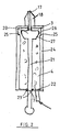
- the preferred metering device shown in FIG. 3 contains a hollow cylinder 28 in which a piston 29 can be moved back and forth, which divides the interior of the hollow cylinder 28 into a rear and a front cylinder space 30, 31.
- the piston 29 is sealed off from the inner wall of the cylinder 28 by means of an O-ring 32 made of silicone.
- the upper cylinder base 33 in the figure is glued to the tubular wall of the cylinder 28 and contains the upper or rear inlet opening 34 for a first liquid, e.g. Water, which is supplied through an inserted connector 35, with which the metering device can be attached, for example, to a dialysis machine.
- a further lateral connector 36 is also provided at the other axial end, which only serves for fastening, but not for supplying liquid.
- the two connectors 35, 36 can make an electrical contact with which the dialysis machine can be signaled that, for example, a chemical disinfection process is to be carried out.
- a central front opening 38 through which a second liquid can be introduced into the front cylinder chamber 31.
- the opening 38 is closed by means of a valve which can open in both directions under pressure.
- the front opening 38 also serves for the exit of the second liquid located in the front cylinder chamber 31 and for the exit of the first liquid of the rear cylinder chamber 30, if it can flow around the piston 29.
- a liquid passage device in the form of a plurality of circular bores 39 is provided in the front (lower) end region of the inner wall of the hollow cylinder 28. If the piston 29 is advanced so far that its sealing ring 32 is in the region of the widening created by the bores 39, the liquid in the rear cylinder chamber 30 can flow around the sealing ring 32 radially on the outside and reaches the front cylinder chamber 31, from which it carries out the remaining amount of liquid (eg disinfectant) and emerges from the opening 38 itself.
- liquid eg disinfectant
- the liquid passage device is formed in that several cylindrical bores are made from the lower end face, which are then closed again in the region of the cylinder bottom 37 by appropriately shaped fillers, which are glued in, for example. Thereafter, the cutouts shown in FIG. 3 remain in the cylinder inner wall.
- the piston 29 shown enlarged in FIG. 5 contains an annular groove 40 for receiving the O-ring 32 and a bore 41 for receiving the coil spring 42, the opposite seat of which is formed by the valve of the opening 38.
- the coil spring 42 is compressed so far that it pushes the piston 29 automatically pushes back out of the area of the widenings 39 when this is no longer acted upon by a liquid pressure. This again creates a liquid-tight separation between the rear and front cylinder chambers 30, 31, so that the front chamber 31 can be refilled without the liquid flowing to the rear chamber 30.
- the piston has the shape of a truncated cone on its (lower) front side, while the cylinder base 37 has a negative truncated cone shape on its inside.
- the angle of inclination of the piston is greater than that of the cylinder bottom. This shape facilitates the smooth running of the liquid in the front cylinder chamber 31 and the outflow of the liquid from the rear cylinder chamber.
- the metering device according to the invention is generally suitable for metering liquid or gaseous media, the piston being able to be advanced not only by excess pressure in the rear cylinder chamber, but also by negative pressure in the front cylinder chamber.
Landscapes
- Health & Medical Sciences (AREA)
- Engineering & Computer Science (AREA)
- Heart & Thoracic Surgery (AREA)
- Urology & Nephrology (AREA)
- Anesthesiology (AREA)
- Life Sciences & Earth Sciences (AREA)
- Chemical Kinetics & Catalysis (AREA)
- Emergency Medicine (AREA)
- Chemical & Material Sciences (AREA)
- Vascular Medicine (AREA)
- Mechanical Engineering (AREA)
- Biomedical Technology (AREA)
- Hematology (AREA)
- General Chemical & Material Sciences (AREA)
- Animal Behavior & Ethology (AREA)
- General Health & Medical Sciences (AREA)
- Public Health (AREA)
- Veterinary Medicine (AREA)
- Physics & Mathematics (AREA)
- Fluid Mechanics (AREA)
- General Physics & Mathematics (AREA)
- External Artificial Organs (AREA)
Claims (10)
- Dispositif de dosage pour l'amenée de deux liquides, desquels au moins un est dosé, caractérisé par un cylindre creux (1, 24, 28), à la paroi interne duquel un piston translatable (2, 20, 29) est adjacent en assurant une étanchéité aux liquides, qui limite une chambre de cylindre avant et une chambre de cylindre arrière (3, 4 ; 31, 30), une ouverture d'entrée (7, 22, 34) pour le premier liquide dans la région arrière du cylindre creux et une ouverture (16, 38) dans la région avant du cylindre creux, à travers laquelle le deuxième liquide dosé est amenable pour remplissage dans la chambre de cylindre avant (3, 31) et hors de laquelle, les deux liquides, par suite de l'avancée du piston, qui est rappelé par la pression du premier liquide agissant sur le côté arrière du piston où la succion agissant sur le côté avant du piston, peuvent sortir, et un dispositif de passage (12, 25, 39) pour le premier liquide, qui, dans une position prédéterminée du piston, permet la sortie du premier liquide dans la chambre de cylindre avant (3, 31) ou bien hors de l'ouverture avant (16, 38) du cylindre creux.
- Dispositif de dosage selon la revendication 1, caractérisé en ce que le passage dans la chambre de cylindre avant est libéré dans la position avancée du piston (2, 20, 29) .
- Dispositif de dosage selon la revendication 1 ou 2, caractérisé en ce que, entre le fond de cylindre creux avant (37) et le piston (29), un dispositif de ressort (42) est agencé, qui est comprimé, lorsque le piston est avancé dans la région du dispositif de passage (39), et dont la force de ressort repousse à nouveau le piston dans une région, dans laquelle celui-ci est adjacent de façon étanche à la paroi intérieure de cylindre, lorsque le piston n'est plus sollicité en direction d'avance par pression ou succion de liquide.
- Dispositif de dosage selon une des revendications 1 à 3, caractérisé en ce qu'avec le piston (2, 20) une tige de traction (6, 21) est reliée, qui, dans la position avancée du piston, fait saillie avec sa section d'extrémité arrière hors d'un perçage de passage ( 7 ) dans la paroi frontale arrière (8) du cylindre creux (1, 24).
- Dispositif de dosage selon la revendication 4, caractérisé en ce que la tige de traction pénétrant la paroi frontale arrière (8) du cylindre creux (1) est un tube (6) creux, qui est reliable avec un conduit (10), qui reste en liaison avec une source du premier liquide.
- Dispositif de dosage selon une des revendications 1 à 5, caractérisé en ce que le piston (2) présente un perçage de passage pourvu d'un organe d'obturation (13), qui permet le passage du premier liquide dans la chambre de cylindre avant (3), lorsque l'organe d'arrêt (13) est déplacé dans une position d'ouverture, que l'organe d'arrêt est un corps d'obturation (13), qui est sollicité, par un dispositif de ressort (14), en direction de la paroi frontale avant (15) du cylindre creux (1), dans la position d'obturation, et que dans la position avancée du piston (2) le corps d'obturation (13) vient en contact sur une partie en saillie (19) restant fixe, qui pousse le corps d'obturation dans la position d'ouverture.
- Dispositif de dosage selon la revendication 6, caractérisé en ce que la partie en saillie est un élément pointu (19) installé dans la région de l'ouverture avant (16) du cylindre creux (1), qui présente au moins un perçage de passage (20), qui reste en liaison avec l'ouverture (16).
- Dispositif de dosage selon une des revendications 1 à 7, caractérisé en ce qu'une ouverture (22, 34) est constituée pour l'entrée du premier liquide dans la chambre de cylindre arrière (4, 30).
- Dispositif de dosage selon les revendications 4 et 8, caractérisé en ce que le perçage de passage (7) pénétré par la tige de traction (21), dans la paroi frontale arrière du cylindre creux (24), est étanché avec étanchéité aux liquides vis-à-vis de la tige de traction.
- Dispositif de dosage selon l'une des revendications 1 à 4, 8 et 9, caractérisé en ce que, dans la région de la section d'extrémité avant du cylindre creux (24, 28), au moins une section périphérique de la paroi intérieure du cylindre creux est élargie, de sorte que dans cette région, un passage (26, 39) est libéré au bord du piston (20, 29).
Priority Applications (1)
| Application Number | Priority Date | Filing Date | Title |
|---|---|---|---|
| AT90105764T ATE92890T1 (de) | 1989-04-20 | 1990-03-27 | Dosiereinrichtung. |
Applications Claiming Priority (4)
| Application Number | Priority Date | Filing Date | Title |
|---|---|---|---|
| DE3913008A DE3913008A1 (de) | 1989-04-20 | 1989-04-20 | Dosiereinrichtung zum dosieren von fluessigkeiten |
| DE3913008 | 1989-04-20 | ||
| DE3941103 | 1989-12-13 | ||
| DE3941103A DE3941103A1 (de) | 1989-12-13 | 1989-12-13 | Desinfektionsverfahren eines dialysierfluessigkeitskreislaufes, geraet zur durchfuehrung derartiger desinfektionsverfahren, wasserversorgungseinrichtung fuer dialysegeraet und dosiereinrichtung zum dosieren von fluessigkeiten |
Publications (2)
| Publication Number | Publication Date |
|---|---|
| EP0393386A1 EP0393386A1 (fr) | 1990-10-24 |
| EP0393386B1 true EP0393386B1 (fr) | 1993-08-11 |
Family
ID=25880113
Family Applications (1)
| Application Number | Title | Priority Date | Filing Date |
|---|---|---|---|
| EP90105764A Expired - Lifetime EP0393386B1 (fr) | 1989-04-20 | 1990-03-27 | Dispositif de dosage |
Country Status (2)
| Country | Link |
|---|---|
| EP (1) | EP0393386B1 (fr) |
| DE (1) | DE59002248D1 (fr) |
Families Citing this family (1)
| Publication number | Priority date | Publication date | Assignee | Title |
|---|---|---|---|---|
| US5480565A (en) * | 1993-10-08 | 1996-01-02 | Levin; Nathan | Methods for disinfecting dialyzers |
Family Cites Families (2)
| Publication number | Priority date | Publication date | Assignee | Title |
|---|---|---|---|---|
| GB1402476A (en) * | 1972-06-19 | 1975-08-06 | Alfa Laval Ab | Fluid apparatus such as liquid measuring apparatus |
| MA18615A1 (fr) * | 1978-11-14 | 1980-07-01 | Xeda Internat Sa | Dispositif de dosage de petites quantites de produits fluides |
-
1990
- 1990-03-27 DE DE9090105764T patent/DE59002248D1/de not_active Expired - Fee Related
- 1990-03-27 EP EP90105764A patent/EP0393386B1/fr not_active Expired - Lifetime
Also Published As
| Publication number | Publication date |
|---|---|
| DE59002248D1 (de) | 1993-09-16 |
| EP0393386A1 (fr) | 1990-10-24 |
Similar Documents
| Publication | Publication Date | Title |
|---|---|---|
| DE69626249T2 (de) | Verteiler für intranasale medikamente | |
| DE69007660T2 (de) | Hydraulisches Komprimierwerkzeug mit Druckentlastungs- und Überdruckventil. | |
| DE602004001374T3 (de) | Tintenpatrone und Tintenstrahldrucker | |
| DE60303675T2 (de) | Verbindungselement und verbindungsvorrichtung für rohre | |
| DE60311866T2 (de) | Mechanisch und hydrodynamisch betriebene aufbrüheinheit | |
| DE19852982C1 (de) | Kartuschenhalter für eine Dialysemaschine | |
| DE3486370T2 (de) | Vorrichtung mit abnehmbarem Behälter für Reinigungsgerät. | |
| DE2953673T1 (de) | Manuelle Flussigkeits-Abgabevorrichtung | |
| DE3308728A1 (de) | Waschvorrichtung fuer ein endoskop | |
| DE3316157A1 (de) | Brueheinrichtung fuer eine selbsttaetig arbeitende kaffeemaschine | |
| DE3637823C2 (de) | Hilfskraftbetätigtes Spannfutter | |
| EP1670380A1 (fr) | Jet dentaire et manche de jet dentaire | |
| EP1467781A1 (fr) | Appareil de traitement dentaire | |
| DE2338267B2 (de) | Zweistufiger pneumatisch-hydraulischer Druckwandler | |
| DE10324307B3 (de) | Schnellkupplungseinheit mit integriertem Rückschlagventil | |
| DE69511336T2 (de) | Ventilvorrichtung zum Ansaugen einer Pumpe, insbesondere für Kaffeemaschinen | |
| EP0285551A2 (fr) | Buse d'injection pour matière thermoplastique | |
| EP3912709B1 (fr) | Dispositif et procédé de mélange des liquides | |
| DE2630569A1 (de) | Zahnbuerstenfuellhalter | |
| EP3258101A1 (fr) | Module de pompe et dispositif de production d'un jet de liquide | |
| DE2349452A1 (de) | Schmelzklebstoff-auftragpistole | |
| EP0436855B1 (fr) | Procédé et dispositif pour la désinfection d'un circuit de dialysat | |
| EP0393386A1 (fr) | Dispositif de dosage | |
| DE102008014281B4 (de) | Verfahren, Mischsystem und Vorrichtung zum Erzeugen eines desinfizierenden Schaumes | |
| DE3913008C2 (fr) |
Legal Events
| Date | Code | Title | Description |
|---|---|---|---|
| PUAI | Public reference made under article 153(3) epc to a published international application that has entered the european phase |
Free format text: ORIGINAL CODE: 0009012 |
|
| AK | Designated contracting states |
Kind code of ref document: A1 Designated state(s): AT BE CH DE DK ES FR GB GR IT LI NL SE |
|
| 17P | Request for examination filed |
Effective date: 19901230 |
|
| 17Q | First examination report despatched |
Effective date: 19921029 |
|
| GRAA | (expected) grant |
Free format text: ORIGINAL CODE: 0009210 |
|
| ITF | It: translation for a ep patent filed | ||
| AK | Designated contracting states |
Kind code of ref document: B1 Designated state(s): AT BE CH DE DK ES FR GB GR IT LI NL SE |
|
| PG25 | Lapsed in a contracting state [announced via postgrant information from national office to epo] |
Ref country code: SE Effective date: 19930811 Ref country code: NL Effective date: 19930811 Ref country code: GR Free format text: LAPSE BECAUSE OF FAILURE TO SUBMIT A TRANSLATION OF THE DESCRIPTION OR TO PAY THE FEE WITHIN THE PRESCRIBED TIME-LIMIT Effective date: 19930811 Ref country code: GB Effective date: 19930811 Ref country code: ES Free format text: THE PATENT HAS BEEN ANNULLED BY A DECISION OF A NATIONAL AUTHORITY Effective date: 19930811 Ref country code: DK Effective date: 19930811 Ref country code: BE Effective date: 19930811 |
|
| REF | Corresponds to: |
Ref document number: 92890 Country of ref document: AT Date of ref document: 19930815 Kind code of ref document: T |
|
| REF | Corresponds to: |
Ref document number: 59002248 Country of ref document: DE Date of ref document: 19930916 |
|
| ET | Fr: translation filed | ||
| NLV1 | Nl: lapsed or annulled due to failure to fulfill the requirements of art. 29p and 29m of the patents act | ||
| PGFP | Annual fee paid to national office [announced via postgrant information from national office to epo] |
Ref country code: FR Payment date: 19940124 Year of fee payment: 5 |
|
| GBV | Gb: ep patent (uk) treated as always having been void in accordance with gb section 77(7)/1977 [no translation filed] |
Effective date: 19930811 |
|
| PGFP | Annual fee paid to national office [announced via postgrant information from national office to epo] |
Ref country code: CH Payment date: 19940309 Year of fee payment: 5 |
|
| PGFP | Annual fee paid to national office [announced via postgrant information from national office to epo] |
Ref country code: AT Payment date: 19940331 Year of fee payment: 5 |
|
| PLBE | No opposition filed within time limit |
Free format text: ORIGINAL CODE: 0009261 |
|
| STAA | Information on the status of an ep patent application or granted ep patent |
Free format text: STATUS: NO OPPOSITION FILED WITHIN TIME LIMIT |
|
| 26N | No opposition filed | ||
| PG25 | Lapsed in a contracting state [announced via postgrant information from national office to epo] |
Ref country code: DE Effective date: 19941201 |
|
| PG25 | Lapsed in a contracting state [announced via postgrant information from national office to epo] |
Ref country code: AT Effective date: 19950327 |
|
| PG25 | Lapsed in a contracting state [announced via postgrant information from national office to epo] |
Ref country code: LI Effective date: 19950331 Ref country code: CH Effective date: 19950331 |
|
| PG25 | Lapsed in a contracting state [announced via postgrant information from national office to epo] |
Ref country code: FR Free format text: LAPSE BECAUSE OF NON-PAYMENT OF DUE FEES Effective date: 19951130 |
|
| REG | Reference to a national code |
Ref country code: CH Ref legal event code: PL |
|
| REG | Reference to a national code |
Ref country code: FR Ref legal event code: ST |
|
| PG25 | Lapsed in a contracting state [announced via postgrant information from national office to epo] |
Ref country code: IT Free format text: LAPSE BECAUSE OF NON-PAYMENT OF DUE FEES;WARNING: LAPSES OF ITALIAN PATENTS WITH EFFECTIVE DATE BEFORE 2007 MAY HAVE OCCURRED AT ANY TIME BEFORE 2007. THE CORRECT EFFECTIVE DATE MAY BE DIFFERENT FROM THE ONE RECORDED. Effective date: 20050327 |