EP0393433A2 - Méthode pour le revêtement de la paroi intérieure d'un tuyau en béton et dispositif pour sa mise en oeuvre - Google Patents
Méthode pour le revêtement de la paroi intérieure d'un tuyau en béton et dispositif pour sa mise en oeuvre Download PDFInfo
- Publication number
- EP0393433A2 EP0393433A2 EP90106562A EP90106562A EP0393433A2 EP 0393433 A2 EP0393433 A2 EP 0393433A2 EP 90106562 A EP90106562 A EP 90106562A EP 90106562 A EP90106562 A EP 90106562A EP 0393433 A2 EP0393433 A2 EP 0393433A2
- Authority
- EP
- European Patent Office
- Prior art keywords
- coating
- wall
- layer
- pipe
- spacers
- Prior art date
- Legal status (The legal status is an assumption and is not a legal conclusion. Google has not performed a legal analysis and makes no representation as to the accuracy of the status listed.)
- Withdrawn
Links
Images

Classifications
-
- B—PERFORMING OPERATIONS; TRANSPORTING
- B28—WORKING CEMENT, CLAY, OR STONE
- B28B—SHAPING CLAY OR OTHER CERAMIC COMPOSITIONS; SHAPING SLAG; SHAPING MIXTURES CONTAINING CEMENTITIOUS MATERIAL, e.g. PLASTER
- B28B21/00—Methods or machines specially adapted for the production of tubular articles
- B28B21/92—Methods or apparatus for treating or reshaping
- B28B21/94—Methods or apparatus for treating or reshaping for impregnating or coating by applying liquids or semi-liquids
-
- F—MECHANICAL ENGINEERING; LIGHTING; HEATING; WEAPONS; BLASTING
- F16—ENGINEERING ELEMENTS AND UNITS; GENERAL MEASURES FOR PRODUCING AND MAINTAINING EFFECTIVE FUNCTIONING OF MACHINES OR INSTALLATIONS; THERMAL INSULATION IN GENERAL
- F16L—PIPES; JOINTS OR FITTINGS FOR PIPES; SUPPORTS FOR PIPES, CABLES OR PROTECTIVE TUBING; MEANS FOR THERMAL INSULATION IN GENERAL
- F16L58/00—Protection of pipes or pipe fittings against corrosion or incrustation
- F16L58/02—Protection of pipes or pipe fittings against corrosion or incrustation by means of internal or external coatings
- F16L58/04—Coatings characterised by the materials used
- F16L58/10—Coatings characterised by the materials used by rubber or plastics
- F16L58/1009—Coatings characterised by the materials used by rubber or plastics the coating being placed inside the pipe
- F16L58/1027—Coatings characterised by the materials used by rubber or plastics the coating being placed inside the pipe the coating being a sprayed layer
Definitions
- the invention relates to a method for coating the inner wall of a concrete pipe with a preferably reactive curing and solvent-free coating composition based on synthetic resin.
- the invention has for its object to provide a method which allows the application of a coating composition in the most uniform layer thickness possible, especially in the case of smaller pipe diameters.
- a coating composition with thixotropic properties is introduced as a supply quantity at one end, preferably the lower pipe end, into the interior of the vertically oriented pipe, liquefied by introducing pulsating forces into the supply quantity and at an essentially constant inflow via an annular gap the inner wall is applied as a layer and is progressively painted in at least one pass in the axial direction.
- This method has the advantage that coating compositions can be applied in a layer thickness that can neither be achieved by hand in the painting nor in the spatula process. It is essential here that a coating with an almost uniform layer thickness can be applied both over the pipe circumference and over the pipe length.
- the method is fundamentally independent of the respective pipe diameter, but can be used with particular advantage for pipes with small nominal widths, the interior of which is no longer "accessible” in the sense that the entire pipe length can be reached by hand from both pipe ends using a hand tool is.
- the use of a thixotropic coating composition ensures that not only is the supply quantity liquefied by the introduction of the pulsating forces, but that the layer is also applied to the inner wall under the influence of the pulsating forces.
- a thin resin film forms on both boundary layers of the coating, both on the sides facing the inner wall and on the free surface, so that there is an overall pore-free inner surface.
- a synthetic resin mortar is preferably used as the coating material, which is essentially composed of a synthetic resin, preferably based on epoxy or polyester resin, and contains at least one, preferably mineral filler and thixotropic agent. Since, for water protection reasons, such resins have to be processed without solvents, it is advisable to use the usual epoxy resin mixtures, in which two resin components reactively harden after mixing. Fire-dried quartz sands are primarily used as mineral fillers, their grain spectrum for thin coatings, ie when applying a coating up to 2 mm thick, is between 0 and 0.35 ⁇ m and their grain spectrum for thick coatings up to 7 mm is 0.06 to 0 .7 mm.
- the axially progressive coating movement is superimposed on a movement pulsating in the axial direction. Due to this superimposed, pulsating movement, the fluidity of the coating composition is maintained until the layer to be applied is smoothed out on the inner wall of the pipe.
- this measure ensures that even with a synthetic resin composition with a high proportion of mineral additives, a thin resin film is formed at least on the free layer surface, which causes a dense surface.
- a base layer is applied in a first operation for applying a thick layer and a fine layer is applied in a second operation after curing.
- a base layer is applied in a first operation for applying a thick layer and a fine layer is applied in a second operation after curing.
- Another embodiment of the invention provides that, in particular for the application of a thin layer after the coating composition has been applied, the surface of the layer is smoothed out in a continuous sweeping movement with superimposed pulsating movement without mass inflow.
- the use of the method according to the invention is advantageous for rough and open-pore concrete surfaces, since the coating here leads to a pore-free surface. Under the effect of the pulsating forces and movements, all pores in the concrete surface are filled and a smooth surface is achieved. Pretreatment of the surface is not necessary.
- a manual coating for the applied surface coating gave an adhesive tensile strength of 3 to 4 N / mm2 and a coating according to the method of the invention gave an adhesive tensile strength of 5 to 5.5 N / mm2. This shows that the anchoring of the coating has been improved by the influence of the pulsating movement during application and the resistance to detachment of the coating is increased.
- the invention further relates to a device for coating the inner wall of a concrete pipe with a coating composition, preferably a reactive curing and solvent-free coating composition based on synthetic resin, in particular for carrying out the method according to the invention with its embodiments.
- a coating composition preferably a reactive curing and solvent-free coating composition based on synthetic resin
- an essentially cylindrical filler body is provided, which is connected to a drive means for the axial passage through the pipe to be coated, and which runs in the circumferential direction and ends at a distance from the inner wall of the pipe in accordance with the intended layer thickness
- Has a scraper edge which, seen in the pulling direction, merges into a conical inlet surface, that at least one inlet opening for the coating composition opens onto the inlet surface, which is connected to a mass supply device, and that an oscillation generator is provided for generating an oscillating movement extending in the pulling direction, which at least least the area of the inlet opening vibrates.
- This arrangement ensures that the thixotropic coating composition flows over the conical inlet surface into the annular gap defined by the coating edge on the one hand and the inner wall of the tube on the other. Since the inlet surface forms a wedge-shaped inlet to the annular gap together with the inner wall, the coating composition still flowing on the inlet surface is pressed against the inner wall of the pipe. The compressive forces acting through the coating edge on the coating material already in contact with the inner pipe wall receive or again cause a certain liquefaction of the compound, so that it can flow into all pores and roughness of the inner pipe wall.
- At least one smoothing sleeve extending in the circumferential direction and made of an elastically deformable material is arranged on the spatula body in the pulling direction behind the coating edge.
- the smoothing sleeve is provided on its inside with a circumferential inflatable body which can be acted upon by a pressure medium. This inflatable body offers the possibility of exerting an additional influence on the layer thickness, in particular compensating for roundness errors in the tube.
- the diameter of the filler body can be increased somewhat, so that behind the (rigid) brushing edge a further (elastic) "brushing edge" forms, through which the layer applied by the rigid coating edge is reworked and in the circumferential direction due to the elastic Adjustment of the smoothing sleeve is evenly distributed.
- This embodiment is particularly suitable for applying a thin coating with a layer thickness of max. 2 mm.
- the filler body is provided with a plurality of spacers distributed uniformly over the circumference, which are on the inner wall of the pipe issue.
- This has the advantage that errors in shape of the pipe to be coated are compensated for much better, and further the advantage that a large number of pipes standing side by side can be coated one after the other without additional manipulations, since only the spatula need be inserted into the pipe interior in each case.
- the particular advantage lies in the fact that the tube provided with a coating that has not yet cured can stand still, so that due to the thixotropic properties of the applied coating composition, any vibration such as that which would bring about transportation is avoided.
- the spacers are preferably attached to the smoothing sleeve in the area of the inflatable body.
- This arrangement has the advantage that roundness errors are compensated for, because the interaction of the smoothing sleeve pressed outwards by the inflatable body on the one hand and the spacers connected to the smoothing sleeve on the other hand allows a layer thickness defined by the height of the spacers to be applied even if the cross sections the pipes are not exactly round.
- the grooves that run in the axial direction when the layer is applied through the spacers in the applied mass layer and are caused by the spacers can then be smoothed out consistently and reliably in a second pass with a spatula without spacers with a low mass supply.
- detachable spacers it is possible with the spatula body that can be used for a defined nominal width Apply layers with different layer thicknesses to the application, since the height of the spacers determines the layer thickness to be applied. It has turned out to be particularly expedient, however, if the spatula body has two smoothing sleeves arranged at a distance from one another. Here, the smoothing sleeve immediately adjacent to the coating edge is provided with the spacers.
- the subsequent smoothing sleeve is continuously smooth.
- Both smoothing sleeves are provided with an inflatable body, wherein the two inflatable bodies can be pressurized independently of one another.
- the coating material can be applied in one operation and the grooves drawn through the spacers can be smoothed out immediately afterwards. Due to the separate pressurization of the second smoothing sleeve, the contact pressure and thus the surface formation can be influenced.
- the mass supply device is formed by a storage container which is arranged on the spatula body and is connected to the vibration generator.
- This arrangement has the advantage that, in particular when using reactive hardening synthetic resin mortar as coating material, a precisely measured supply quantity can be used, which is easy to handle due to the thixotropic properties and only after the filler body has been introduced into the interior of the pipe under the influence of those generated by the vibration generator pulsating movements liquefied and then runs towards the coating edge.
- the inlet opening opening onto the inlet surface is formed by a circumferential slot in the bottom region of the storage container. The coating composition then flows over the preferably adjustable slot width in a uniform layer of mass to the coating edge, so that the amount tapering in layers is practically only pressed against the inner wall and smoothed out.
- the storage container is formed by a collar which is fastened in a height-adjustable manner on the spatula body, which tapers conically in the pulling direction.
- the collar forms the side wall of the storage container, while the lower edge of the collar facing the conically tapering part of the spatula defines the inlet opening with its spacing.
- the vibration generator is arranged in the spatula body, preferably below the storage container.
- the advantage of this arrangement is that the oscillating movements running in the axial direction make the thixotropic coating composition located in the storage container flowable and that the flowability is then maintained during the feed to the coating edge. Since the oscillating movements occurring in the axial direction are superimposed on the constant pulling movement, the coating mass pressed against the inner wall of the tube is then "rubbed" by the surface of the smoothing collar, the coating mass being pressed into the pores of the inner wall of the tube and any air bubbles being pressed out of the mass will. This also results in an optimal introduction of the vibration energy.
- two unbalances which are adjustable in speed and are driven in opposite directions are provided as vibration generators.
- This arrangement has the advantage that both the forces and the frequency of the pulsating movements can be set precisely, so that, depending on different thixotropy properties of the coating compositions used, an optimal flow behavior of the coating composition used in each case can be set when applied to the inner wall.
- the spatula body is connected at its upper end to a support tube extending in the pulling direction, which is several times longer than the spatula body and which is attached with its free end to a hoist as a drive means and through which the Power supply lines for vibrators and inflatable bodies are passed through.
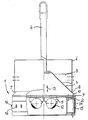
- a spatula body 1 which consists of a substantially cylindrical base body 2, which is followed by a conical head part 3 at the top.
- a support tube 4 is fastened to the tapered head part 3, with which the spatula body can be moved in the vertical direction via a lifting device.
- a collar 6 is fastened via narrow webs 5 in such a way that it can be adjusted with its lower edge 7 at a distance from the conical head part 3 is.
- the collar 6 with the conical head part 3 lying in its interior forms a storage container for receiving the coating material.
- the collar 6 is smaller in diameter than the cylindrical base part, so that a free inlet surface 10 is present between the lower edge 7 of the collar 6 defining a slot-shaped passage opening 8 and a brush edge 9 formed at the transition between the cylindrical base part 2 and the conical head part 3 , on which the liquefied coating material emerging from the storage container can spread in a pre-layering.
- two counter-rotating, controllable electric motors 11 are arranged, which are only indicated schematically here, by means of which two unbalances 12 are operated in opposite directions to one another, so that the spatula body 1 can be set in pulsating movements in the direction of arrow 13 .
- a pressure medium, preferably compressed air, can be supplied via the inflatable body by means of a hose line, not shown here, so that the smoothing sleeve is inflated to a certain extent, but is at least elastically supported with respect to the cylindrical base body 2.
- web-shaped spacers 16 are detachably attached evenly distributed over the circumference and come into contact with the inner wall of the tube during operation. The height of the web-shaped spacers 16 determines the layer thickness to be applied.
- the support tube 4 is attached at its upper end with the interposition of a suspension member provided with a damping member on a hoist, not shown here, so that the spatula body 1 inserted into a vertical tube can be moved slowly from bottom to top and at the same time via the counter-rotating Imbalance of this progressive movement an oscillating up and down movement can be superimposed in the same orientation.
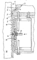
- Fig. 2 shows the top view of the filler body in a half section.
- a coating material with thixotropic properties for example a synthetic resin mortar on a two-component epoxy resin base with thixotropic agent and fire-dried fine-grained quartz sand as filler, has been introduced into the storage container defined by the conical head part 3 and the collar 6, the filler body is inserted into a filler by means of the lifting device vertically standing concrete pipe so far that the brushing edge 9 is at the level of the end edge of the pipe standing on the bell end.
- the vibration generator 11 is put into operation, so that the pulsating movements of the plastic mortar in the storage container become flowable and run through the continuously slit-shaped inlet opening 8 against the inner wall 17 of the concrete pipe 18 to be coated, thereby forming a "ring" on the Inner wall 17 creates.
- the filler body is slowly lifted over the hoist, so that the "ring" of coating compound in the remaining space 19 between the inner wall manure 17 and the cylindrical peripheral surface of the filler body 1 is drawn and passed on the inner wall 17.
- the smoothing sleeve 14 is moved against the inner wall 17 of the tube, so that the spacers 16 come to rest on the surface. Since the spacers 16 are evenly distributed on the circumference and their distance from one another on the one hand and the thickness of the smoothing sleeve 14 are dimensioned such that the cylindrical basic shape of the smoothing sleeve is retained, the smoothing sleeve adapts to the cross-sectional contour of the pipe to be coated at any time, so that all out-of-roundness is compensated for and a gap with the same thickness arises over the circumference and the coating material applied is thus smoothed out in the same thickness.
- the coating composition loses its fluidity due to the thixotropic property, so that despite the vertical alignment of the tube, the applied layer "stands" on the inner wall and no longer runs downwards can. After the filler body has been completely pulled out of the pipe, it must remain at rest until the coating composition has hardened completely.
- the small excess of coating material is smoothed by hand on the end face of the tip end, so that this area is also provided with a corrosion protection layer.
- the same spatula body with the spacers removed or another spatula body with a smooth sleeve is again inserted into the tube, with a correspondingly small amount in the storage container is included in coating composition.
- the coating compound is liquefied again by the pulsating movements and runs over the inlet surface 10 to the scraper edge 9 and is then drawn into the small gap between the scraper edge 9 and the surface of the hardened coating when the filler body moves upwards. In the area of the longitudinal grooves remaining from the first operation, these are filled with coating compound and completely filled out via the smoothing sleeve, which may be pre-tensioned via the inflatable body.
- the energy supply for the vibration generator and the supply of the pressure medium to the inflatable body 15 takes place via corresponding feed lines, which are introduced through the support tube 4 into the filler body in a manner not shown are. Since the support tube 4 is several times longer than the height of the filler body, the filler body 1 can also be pulled through a concrete pipe from bottom to top using a simple cable hoist, for example a crane with slow lift, from top to bottom.
Landscapes
- Engineering & Computer Science (AREA)
- Mechanical Engineering (AREA)
- General Engineering & Computer Science (AREA)
- Manufacturing & Machinery (AREA)
- Chemical & Material Sciences (AREA)
- Ceramic Engineering (AREA)
- Application Of Or Painting With Fluid Materials (AREA)
- Protection Of Pipes Against Damage, Friction, And Corrosion (AREA)
Applications Claiming Priority (2)
| Application Number | Priority Date | Filing Date | Title |
|---|---|---|---|
| DE19893912933 DE3912933A1 (de) | 1989-04-20 | 1989-04-20 | Verfahren zum beschichten der innenwandung eines betonrohres und vorrichtung zur durchfuehrung des verfahrens |
| DE3912933 | 1989-04-20 |
Publications (2)
| Publication Number | Publication Date |
|---|---|
| EP0393433A2 true EP0393433A2 (fr) | 1990-10-24 |
| EP0393433A3 EP0393433A3 (fr) | 1991-12-18 |
Family
ID=6379030
Family Applications (1)
| Application Number | Title | Priority Date | Filing Date |
|---|---|---|---|
| EP19900106562 Withdrawn EP0393433A3 (fr) | 1989-04-20 | 1990-04-05 | Méthode pour le revêtement de la paroi intérieure d'un tuyau en béton et dispositif pour sa mise en oeuvre |
Country Status (3)
| Country | Link |
|---|---|
| EP (1) | EP0393433A3 (fr) |
| DD (1) | DD298753A5 (fr) |
| DE (1) | DE3912933A1 (fr) |
Cited By (13)
| Publication number | Priority date | Publication date | Assignee | Title |
|---|---|---|---|---|
| WO1996006298A1 (fr) * | 1994-08-24 | 1996-02-29 | Thyssen Schachtbau Rohrtechnik Gmbh | Procede de renovation de conduites et de puits d'alimentation et d'elimination |
| WO1996006299A1 (fr) * | 1994-08-20 | 1996-02-29 | Thyssen Schachtbau Rohrtechnik Gmbh | Procede de revetement interieur de corps creux |
| WO1996006710A1 (fr) * | 1994-08-29 | 1996-03-07 | Gevi Gesellschaft Für Entwicklung Und Vertrieb Industrieller, Zerstörungsfreier Und Umweltfreundlicher Verfahrenstechniken Zur Innensanierung Von Rohrleitungen Mbh | Procede permettant de renover des canalisations |
| US6739950B1 (en) | 2002-12-09 | 2004-05-25 | Joerg Kruse | Pipe renovating system and method |
| US7160574B1 (en) | 2002-08-28 | 2007-01-09 | Pipe Restoration Technologies, Llc | Barrier coating corrosion control methods and systems for interior piping systems |
| US7348039B2 (en) | 2005-12-21 | 2008-03-25 | Jak Aklian | Method of making a newly installed plumbing system renewable |
| US7858149B2 (en) | 2002-08-28 | 2010-12-28 | Pipe Restoration Technologies, Llc | Methods and systems for coating and sealing inside piping systems |
| US8399813B2 (en) | 2002-08-28 | 2013-03-19 | Pipe Restoration Technologies, Llc | Portable heating apparatus for heating interior piping systems |
| US8524320B1 (en) | 2002-08-28 | 2013-09-03 | Pipe Restoration Technologies, Llc | Process for coating the interior surface of water service lines |
| CN103411096A (zh) * | 2013-08-15 | 2013-11-27 | 复旦大学 | 一种大口径耐磨耐蚀三元复合变径管的制作方法 |
| US8696823B1 (en) * | 2002-08-28 | 2014-04-15 | Pipe Restoration Technologies, Llc | Methods and systems for abrasive cleaning and barrier coating/sealing of pipes |
| US9611973B2 (en) | 2002-08-28 | 2017-04-04 | Pipe Restoration Technologies, Llc | Process for coating the interior surface of water service lines |
| EP3470724A1 (fr) * | 2017-10-10 | 2019-04-17 | Kipp Umwelttechnik GmbH | Procédé et dispositif de revêtement intérieur des tuyaux et / ou de conduites |
Families Citing this family (1)
| Publication number | Priority date | Publication date | Assignee | Title |
|---|---|---|---|---|
| DE10005943A1 (de) * | 2000-02-09 | 2001-10-31 | Mekuma Mecklenburgische Kunsts | Verfahren und Anlage zur Innenbeschichtung eines rohrförmigen Außenkörpers |
Family Cites Families (7)
| Publication number | Priority date | Publication date | Assignee | Title |
|---|---|---|---|---|
| DE1577735C3 (de) * | 1965-11-30 | 1975-02-06 | Felten & Guilleaume Carlswerk Ag, 5000 Koeln | Vorrichtung zum Herstellen einer dünnen dielektrischen Schicht auf der Innenwand des Metallrohres eines Hohlleiters |
| FR2405798A1 (fr) * | 1977-08-25 | 1979-05-11 | Ato Chimie | Dispositif pour le revetement interieur de tuyaux de grand diametre |
| DE3115985A1 (de) * | 1981-04-22 | 1982-11-11 | H.W. Steenweg GmbH, 4440 Rheine | Verfahren zur herstellung von mit einer innenauskleidung aus kunststoff o.dgl. versehenen betonrohren sowie vorrichtung zur durchfuehrung des verfahrens |
| GB2122300B (en) * | 1982-06-11 | 1985-07-24 | William John Appleton | Repairing drains and underground pipelines |
| DD237986A1 (de) * | 1985-06-07 | 1986-08-06 | Wasserbau Spezialbau Kom | Vorrichtung zur innenauskleidung von hohlkoerpern |
| JPH0720568B2 (ja) * | 1986-11-05 | 1995-03-08 | 株式会社ハツコ− | 管内面ライニング用ピグ |
| CH674172A5 (fr) * | 1987-07-09 | 1990-05-15 | Intertechno Ag |
-
1989
- 1989-04-20 DE DE19893912933 patent/DE3912933A1/de not_active Withdrawn
-
1990
- 1990-04-05 EP EP19900106562 patent/EP0393433A3/fr not_active Withdrawn
- 1990-04-06 DD DD33954690A patent/DD298753A5/de not_active IP Right Cessation
Cited By (35)
| Publication number | Priority date | Publication date | Assignee | Title |
|---|---|---|---|---|
| WO1996006299A1 (fr) * | 1994-08-20 | 1996-02-29 | Thyssen Schachtbau Rohrtechnik Gmbh | Procede de revetement interieur de corps creux |
| WO1996006298A1 (fr) * | 1994-08-24 | 1996-02-29 | Thyssen Schachtbau Rohrtechnik Gmbh | Procede de renovation de conduites et de puits d'alimentation et d'elimination |
| WO1996006710A1 (fr) * | 1994-08-29 | 1996-03-07 | Gevi Gesellschaft Für Entwicklung Und Vertrieb Industrieller, Zerstörungsfreier Und Umweltfreundlicher Verfahrenstechniken Zur Innensanierung Von Rohrleitungen Mbh | Procede permettant de renover des canalisations |
| US5924913A (en) * | 1994-08-29 | 1999-07-20 | Gevi | Process for renovating pipes |
| US8795768B2 (en) | 2002-08-28 | 2014-08-05 | Pipe Restoration Technologies, Llc | Methods and systems for coating and sealing inside of piping systems |
| US9744561B2 (en) | 2002-08-28 | 2017-08-29 | Pipe Restoration Technologies, Llc | Barrier coating corrosion control methods and systems for interior walls of pipe in underground piping |
| US10449569B2 (en) | 2002-08-28 | 2019-10-22 | Pipe Restoration Technologies, Llc | Process for coating the interior surface of non-metallic pipes with metal valves and metal fittings |
| US7517409B1 (en) | 2002-08-28 | 2009-04-14 | Pipe Restoration Technologies, Llc | Barrier coating corrosion control methods and systems for interior piping systems |
| US7858149B2 (en) | 2002-08-28 | 2010-12-28 | Pipe Restoration Technologies, Llc | Methods and systems for coating and sealing inside piping systems |
| US8206783B2 (en) | 2002-08-28 | 2012-06-26 | Pipe Restoration Technologies, Llc | Barrier coating corrosion control methods and systems for interior piping systems |
| US8343579B2 (en) | 2002-08-28 | 2013-01-01 | Pipe Restoration Technologies, Llc | Methods and systems for coating and sealing inside of piping systems |
| US8354140B2 (en) | 2002-08-28 | 2013-01-15 | Pipe Restoration Technologies, Llc | Barrier coating corrosion control methods and systems for interior piping systems |
| US8399813B2 (en) | 2002-08-28 | 2013-03-19 | Pipe Restoration Technologies, Llc | Portable heating apparatus for heating interior piping systems |
| US8524320B1 (en) | 2002-08-28 | 2013-09-03 | Pipe Restoration Technologies, Llc | Process for coating the interior surface of water service lines |
| US10279375B2 (en) | 2002-08-28 | 2019-05-07 | Pipe Restoration Technologies, Llc | Process for coating the interior surface of non-metallic pipes with metal valves and metal fittings |
| US8696823B1 (en) * | 2002-08-28 | 2014-04-15 | Pipe Restoration Technologies, Llc | Methods and systems for abrasive cleaning and barrier coating/sealing of pipes |
| US10076770B2 (en) | 2002-08-28 | 2018-09-18 | Pipe Restoration Technologies, Llc | Processes for coating the interior surfaces of nonmetal materials |
| US8887660B2 (en) | 2002-08-28 | 2014-11-18 | Pipe Restoration Technologies, Llc | Barrier coating corrosion control methods and systems for interior piping systems |
| US8895905B2 (en) | 2002-08-28 | 2014-11-25 | Pipe Restoration Technologies, Llc | Portable heating apparatus for heating interior piping systems |
| US10076769B2 (en) | 2002-08-28 | 2018-09-18 | Pipe Restoration Technologies, Llc | Processes for coating the interior surfaces of nonmetal pipes |
| US9352357B2 (en) | 2002-08-28 | 2016-05-31 | Pipe Restoration Technologies, Llc | Methods and systems for coating and sealing inside piping systems |
| US9446429B2 (en) | 2002-08-28 | 2016-09-20 | Pipe Restoration Technologies, Llc | Barrier coating corrosion control methods and systems for interior piping systems |
| US9555453B2 (en) | 2002-08-28 | 2017-01-31 | Pipe Restoration Technologies, Llc | Methods and systems for abrasive cleaning and barrier coating/sealing of pipes |
| US9611973B2 (en) | 2002-08-28 | 2017-04-04 | Pipe Restoration Technologies, Llc | Process for coating the interior surface of water service lines |
| US9889470B2 (en) | 2002-08-28 | 2018-02-13 | Pipe Restoration Technologies, Llc | Processes for coating the interior surfaces of nonmetal pipes |
| US9724730B2 (en) | 2002-08-28 | 2017-08-08 | Pipe Restoration Technologies, Llc | Methods and systems for coating and sealing inside piping systems |
| US7160574B1 (en) | 2002-08-28 | 2007-01-09 | Pipe Restoration Technologies, Llc | Barrier coating corrosion control methods and systems for interior piping systems |
| US9764354B2 (en) | 2002-08-28 | 2017-09-19 | Pipe Restoration Technologies, Llc | Process for coating the interior surface of underground pipes |
| US9889469B2 (en) | 2002-08-28 | 2018-02-13 | Pipe Restoration Technologies, Llc | Process for coating the interior surfaces of pipes made of nonmetal materials |
| US6739950B1 (en) | 2002-12-09 | 2004-05-25 | Joerg Kruse | Pipe renovating system and method |
| US7348039B2 (en) | 2005-12-21 | 2008-03-25 | Jak Aklian | Method of making a newly installed plumbing system renewable |
| US9273815B2 (en) | 2012-02-07 | 2016-03-01 | Pipe Restoration Technologies, Llc | Process for coating the interior surface of water service lines |
| CN103411096B (zh) * | 2013-08-15 | 2017-06-06 | 复旦大学 | 一种大口径耐磨耐蚀三元复合变径管的制作方法 |
| CN103411096A (zh) * | 2013-08-15 | 2013-11-27 | 复旦大学 | 一种大口径耐磨耐蚀三元复合变径管的制作方法 |
| EP3470724A1 (fr) * | 2017-10-10 | 2019-04-17 | Kipp Umwelttechnik GmbH | Procédé et dispositif de revêtement intérieur des tuyaux et / ou de conduites |
Also Published As
| Publication number | Publication date |
|---|---|
| EP0393433A3 (fr) | 1991-12-18 |
| DE3912933A1 (de) | 1990-10-25 |
| DD298753A5 (de) | 1992-03-12 |
Similar Documents
| Publication | Publication Date | Title |
|---|---|---|
| DE69519567T2 (de) | Verfahren und vorrichtung zum aufspritzen von mörtel auf die innenwand eines mannlochs | |
| EP0393433A2 (fr) | Méthode pour le revêtement de la paroi intérieure d'un tuyau en béton et dispositif pour sa mise en oeuvre | |
| AT412015B (de) | Verfahren und vorrichtung zum auskleiden einer rohrleitung oder eines kanals | |
| DE2752072C2 (de) | Verfahren und Vorrichtung zum Abdichten von undichten Muffenverbindungen an Rohrleitungen, insbesondere an unterirdisch verlegten | |
| CH636649A5 (de) | Voroeffnerwalze fuer eine offenend-spinnmaschine. | |
| DE3235506A1 (de) | Wiederherstellungseinrichtung fuer stroemungsmittelkanaele | |
| DE1955488A1 (de) | Verfahren und Vorrichtung zum Herabsetzen des Stroemungswiderstandes und/oder zum Abdichten von Rohrleitungen | |
| DE3400910A1 (de) | Leitungsrohr fuer stark abrasive, stroemungsfaehige medien und verfahren zu seiner herstellung | |
| EP0151930A2 (fr) | Procédé pour la fabrication d'un élément tubulaire et tuyau composite obtenu par ledit procédé | |
| DE102013108498A1 (de) | Verfahren und Vorrichtung zur Herstellung von beschichteten und insbesondere lackierten Bauplatten und zugehörige lackierte Bauplatte | |
| CH677076A5 (fr) | ||
| DE4026116A1 (de) | Verfahren und vorrichtung zum sanieren von rohren | |
| DE3807511A1 (de) | Verfahren zur herstellung von betonrohren und rohrpresse zur durchfuehrung des verfahrens | |
| DD284737A5 (de) | Verfahren und vorrichtung zum verlegen von kunststoffrohren | |
| AT393312B (de) | Verfahren zur reparatur von rohrleitungen und einrichtung zur durchfuehrung dieses verfahrens | |
| DE69302906T2 (de) | Vorrichtung und verfahren zum herstellen von bauelementen aus beton | |
| DE3123376A1 (de) | Verfahren und vorrichtung zum instandsetzen alter, aus einzelnen rohren zusammengesetzter, erdverlegter rohrleitungen | |
| CH685568A5 (de) | Verfahren zum Ausfugen von Pflastersteinanordnungen. | |
| EP0699862B1 (fr) | Procédé pour la rénovation de canalisations penchées | |
| DE4004539C2 (fr) | ||
| EP0509502B1 (fr) | Buse pour l'application de mortier PCC prêt-à-l'emploi | |
| DE3801469A1 (de) | Verfahren zum sanieren einer im erdreich verlegten rohrleitung | |
| DE63765C (de) | Walzverfahren zur Herstellung von Hohlgegenständen aus plastischer Masse | |
| DE4226938C1 (fr) | ||
| DE20308360U1 (de) | Vorrichtung zur Herstellung von mehrschichtigen Betonrohren |
Legal Events
| Date | Code | Title | Description |
|---|---|---|---|
| PUAI | Public reference made under article 153(3) epc to a published international application that has entered the european phase |
Free format text: ORIGINAL CODE: 0009012 |
|
| AK | Designated contracting states |
Kind code of ref document: A2 Designated state(s): AT BE CH DE FR LI LU NL |
|
| PUAL | Search report despatched |
Free format text: ORIGINAL CODE: 0009013 |
|
| AK | Designated contracting states |
Kind code of ref document: A3 Designated state(s): AT BE CH DE FR LI LU NL |
|
| STAA | Information on the status of an ep patent application or granted ep patent |
Free format text: STATUS: THE APPLICATION IS DEEMED TO BE WITHDRAWN |
|
| 18D | Application deemed to be withdrawn |
Effective date: 19920620 |