EP0393596A2 - Vorrichtung zum Steuern der Drehmomentverteilung für ein Fahrzeug mit Allradantrieb - Google Patents
Vorrichtung zum Steuern der Drehmomentverteilung für ein Fahrzeug mit Allradantrieb Download PDFInfo
- Publication number
- EP0393596A2 EP0393596A2 EP90107276A EP90107276A EP0393596A2 EP 0393596 A2 EP0393596 A2 EP 0393596A2 EP 90107276 A EP90107276 A EP 90107276A EP 90107276 A EP90107276 A EP 90107276A EP 0393596 A2 EP0393596 A2 EP 0393596A2
- Authority
- EP
- European Patent Office
- Prior art keywords
- wheel speed
- vehicle
- determining
- driving force
- control system
- Prior art date
- Legal status (The legal status is an assumption and is not a legal conclusion. Google has not performed a legal analysis and makes no representation as to the accuracy of the status listed.)
- Granted
Links
- 230000001133 acceleration Effects 0.000 claims description 27
- 230000007423 decrease Effects 0.000 claims description 6
- 230000002159 abnormal effect Effects 0.000 description 2
- 230000005540 biological transmission Effects 0.000 description 2
- 230000003247 decreasing effect Effects 0.000 description 2
- 238000000034 method Methods 0.000 description 2
- 238000010586 diagram Methods 0.000 description 1
- 230000000694 effects Effects 0.000 description 1
- 238000009434 installation Methods 0.000 description 1
Images


Classifications
-
- B—PERFORMING OPERATIONS; TRANSPORTING
- B60—VEHICLES IN GENERAL
- B60K—ARRANGEMENT OR MOUNTING OF PROPULSION UNITS OR OF TRANSMISSIONS IN VEHICLES; ARRANGEMENT OR MOUNTING OF PLURAL DIVERSE PRIME-MOVERS IN VEHICLES; AUXILIARY DRIVES FOR VEHICLES; INSTRUMENTATION OR DASHBOARDS FOR VEHICLES; ARRANGEMENTS IN CONNECTION WITH COOLING, AIR INTAKE, GAS EXHAUST OR FUEL SUPPLY OF PROPULSION UNITS IN VEHICLES
- B60K23/00—Arrangement or mounting of control devices for vehicle transmissions, or parts thereof, not otherwise provided for
- B60K23/08—Arrangement or mounting of control devices for vehicle transmissions, or parts thereof, not otherwise provided for for changing number of driven wheels, for switching from driving one axle to driving two or more axles
- B60K23/0808—Arrangement or mounting of control devices for vehicle transmissions, or parts thereof, not otherwise provided for for changing number of driven wheels, for switching from driving one axle to driving two or more axles for varying torque distribution between driven axles, e.g. by transfer clutch
-
- B—PERFORMING OPERATIONS; TRANSPORTING
- B60—VEHICLES IN GENERAL
- B60W—CONJOINT CONTROL OF VEHICLE SUB-UNITS OF DIFFERENT TYPE OR DIFFERENT FUNCTION; CONTROL SYSTEMS SPECIALLY ADAPTED FOR HYBRID VEHICLES; ROAD VEHICLE DRIVE CONTROL SYSTEMS FOR PURPOSES NOT RELATED TO THE CONTROL OF A PARTICULAR SUB-UNIT
- B60W2520/00—Input parameters relating to overall vehicle dynamics
- B60W2520/12—Lateral speed
- B60W2520/125—Lateral acceleration
-
- B—PERFORMING OPERATIONS; TRANSPORTING
- B60—VEHICLES IN GENERAL
- B60W—CONJOINT CONTROL OF VEHICLE SUB-UNITS OF DIFFERENT TYPE OR DIFFERENT FUNCTION; CONTROL SYSTEMS SPECIALLY ADAPTED FOR HYBRID VEHICLES; ROAD VEHICLE DRIVE CONTROL SYSTEMS FOR PURPOSES NOT RELATED TO THE CONTROL OF A PARTICULAR SUB-UNIT
- B60W2520/00—Input parameters relating to overall vehicle dynamics
- B60W2520/28—Wheel speed
Definitions
- the present invention relates to a torque split control system for controlling a driving force distribution between front and rear wheels of a four wheel drive vehicle, and more specifically to a torque split control system which can control the driving force distribution adequately in accordance with a wheel speed difference between front and rear wheels without receiving undesired influences of a tire diameter difference between the front and rear wheels.
- Japanese Patent Provisional (unexamined, KOKAI) Publication No. 63-13331 shows a conventional driving force distribution control system which controls a driving force distribution between front and rear wheels by controlling an engagement force of a torque distributing transfer clutch in accordance with a wheel speed difference between front and rear wheel speeds detected by wheel speed sensors.
- this conventional control system tends to increases the clutch engagement force excessively especially in a high vehicle speed range when the front and rear wheel tire diameters become different from each other.
- the measured wheel speed difference DVw between the front and rear wheels is equal to a sum of a wheel speed difference DVs due to drive wheel slip, and a wheel speed difference DVt due to a difference between the front wheel tire diameter and the rear wheel tire diameter
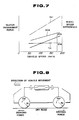
- this conventional control system increases the clutch engagement force as shown by a line Tm′ in Fig. 7, in accordance with the measured wheel speed difference DVw, without considering the wheel speed difference DVt due to the tire diameter difference.
- there arise undesired up-and-down vibrations and an excessive increase in differential oil temperature due to excessive heat generated by clutch slippage ( DVs + DVt).
- the tire diameters of the front and rear wheels are more or less unequal because of difference in operating condition such as tire air pressure and wheel load, inequality in tire wear, intentional installation of tires of different sizes, or usage of a tomporary spare tire.
- a driving force distribution control system for a vehicle comprises a torque distributing means, first and second sensing means, and first, second and third processing means.
- the driving force distributing means comprises a primary drive means for transmitting a driving force from an engine of the vehicle to primary drive wheels such as rear wheels of the vehicle, and a secondary drive means for transmitting a driving force from the engine to secondary drive wheels such as front wheels of the vehicle through a torque distributing clutch capable of varying the driving force transmitted to the secondary drive wheels in response to a control signal.
- the first sensing means determines a measured wheel speed difference between a primary wheel speed of the primary wheels and a secondary wheel speed of the secondsary wheels.
- the second sensing means determines a vehicle speed of the vehicle.
- the first processing means determines a correction quantity in accordance with the vehicle speed.
- the second processing means determines a corrected wheel speed difference which is a difference resulting from subtraction of the correction quantity from the measured wheel speed difference determined by the first sensing means.
- the third processing means determines a desired clutch engagement force in accordance with the corrected wheel speed difference, and produces the above-mentioned control signal representing the desired clutch engagement force.
- Fig. 1 shows one example of the control system according to the invention.
- the control system of this example includes the primary drive means 102 for transmitting the driving force from the engine 101 to the primary drive wheels 103, the secondary drive means 104 for transmitting the driving force from the engine to the secondary drive wheels 105 through the torque distributing clutch 106, the first sensing means 107 for determining the measured wheel speed difference, the second sensing means 108 for determining the vehicle speed, the first processing means 109 for determining the correction quantity, the second processing means 110 for determining the corrected wheel speed difference, and the third processing means 111 for determining the desired clutch engagement force and producing the control signal.
- the control system may further includes a third sensing means 112 for sensing a lateral acceleration of the vehicle, and a gain determining means 113 for determining a control gain as in the illustrated embodiment.
- FIGs. 2-6 One embodiment of the present invention is shown in Figs. 2-6.
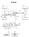
- Fig. 2 shows a 4WD vehicle equipped with a torque split control system (driving force distribution control system).
- the vehicle has a drive system which includes an engine 1, a transmission 2, a transfer input shaft 3, a rear propeller shaft 4, a rear differential 5, rear wheels 6, a transfer output shaft 7, a front propeller shaft 8, a front differential 9, front wheels 10, and a transfer 11.
- the rear wheels 6 are primary drive wheels
- the front wheels 10 are secondary drive wheels.
- engine torque is transmitted to the rear wheels 6 through a rear drive line which serves as a primary drive means for transmitting engine torque directly to the primary drive wheels, and transmitted to the front wheels 10 through a front drive line which serves as a secondary drive means having a torque distribution clutch (or a transfer clutch).
- the torque distribution clutch is a wet type multiple disc clutch provided in the transfer 11.
- the engine torque is transmitted directly to the rear wheels 6.
- the engine torque is transmitted to the front wheels 10 through the torque distributing clutch which is capable of continuously varying the torque transmitted to the front wheels, and completely disconnecting the front wheels 10 from the engine 1.
- the transfer and its torque distributing clutch are illustrated and explained more in detailin commonly assigned United States Patents Numbers 4,754,834; 4,757,870; 4,773,500; 4,776,424; 4,846,298; 4,874,056 and 4,887,689, and commonly assigned United States Applications Serial Nos. 07/254,875; 07/255,820; 07/277,377 and 07/255,939.
- the related explanations and figures of these patents are herein incorporated by reference.
- the torque split (driving force distribution) control system further includes a hydraulic system 20 for producing a control oil pressure Pc supplied to the distributing clutch, a group of various sensors 30, and a torque split control unit 40.
- the control unit 40 produces a dither current i* in accordance with output signals of the sensors 30, and controls the clutch engagement force of the torque distribution clutch of the transfer 11 by sending the dither current to a solenoid valve 28 of the hydraulic system 20.
- the hydraulic system 20 includes a relief switch 21, a motor 22, an oil reservoir tank 23, an oil pressure pump 24, a check valve 25, an accumulator 26, and the above-mentioned solenoid valve 28.
- the motor 22 is turned on and off by the relief switch 21, and drives the oil pump 24 which sucks the oil from the reservoir tank 23.
- the oil pressure discharged from the pump 24 (primary oil pressure) is supplied through the check valve 25, and stored in the accumulator 26.
- the solenoid valve 28 receives a line pressure (secondary pressure) from the accumulator 26, and produces the control oil pressure Pc in accordance with the dither current i* sent from the control unit 40.
- the control oil pressure Pc is supplied to the torque distributing clutch of the transfer 11 through an oil pipe 29. In this way, the control unit 40 can continuously vary the engagement force of the torque distributing clutch.
- the sensor group 30 of this embodiment includes a front left wheel rotation sensor 30a for sensing the number of revolutions Nfl of the front left wheel 10, a front right wheel rotation sensor 30b for sensing the number of revolutions Nfr of the front right wheel 10, a rear left wheel rotation sensor 30C for sensing the number of revolutions Nrl of the rear left wheel 6, a rear right wheel rotation sensor 30d for sensing the number of revolutions Nrr of the rear right wheel 6, a first lateral acceleration sensor 30e, and a second lateral acceleration sensor 30f.
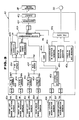
- the torque split control unit 40 includes a circuit 40a for receiving the signal of the front left wheel rotation sensor 30a and determining a front left wheel speed Vwfl, a circuit 40b for receiving the signal of the front right wheel rotation sensor 30b and determining a front right wheel speed Vwfr, a circuit 40c for receiving the signal of the rear left wheel rotation sensor 30c and determining a rear left wheel speed Vwrl, and a circuit 40d for receiving the signal of the rear right wheel rotation sensor 30d and determining a rear right wheel speed Vwrr.
- the torque split control unit 40 further includes a circuit 40e connected with the circuits 40a and 40b, for determining a front wheel speed Vwf, a circuit 40f connected with the circuits 40c and 40d, for determining a rear wheel speed Vwr, and a circuit 40g connected with the circuits 40e and 40f, for determining a measured front and rear wheel speed difference DVw.
- the front wheel speed Vwf is an average (arithmetic mean) of Vwfl and Vwfr
- the rear wheel speed Vwr is an average (arithmetic mean) of Vwrl and Vwrr.
- the measured front and rear wheel speed difference DVw is a difference obtained by subtracting the front wheel speed Vwf (i.e. a secondary wheel speed) from the rear wheel speed Vwr (i.e. a primary wheel speed).
- the torque split control unit 40 of this embodiment further includes a circuit 40h for computing a desired clutch engagement force Tm, a Tm-i converting circuit 40i for converting the output signal of the circuit 40h to a current signal i, an output circuit 40j for outputting the dither current i*, a circuit 40k for determining a correction quantity Qi, a circuit 401 for determining a lateral acceleration Yg of the vehicle by using an output signal Yg1 of the first lateral acceleration sensor 30e and an output signal Yg2 of the second lateral acceleration sensor 30f, a circuit 40m for determining a gain Kh in accordance with the lateral acceleration Yg, a circuit 40n for detecting an abnormal condition such as a broken connection which breaks the continuity of each rotation sensor, a ⁇ circuit 40o for detecting a short-circuit of each rotation sensor, a circuit 40p for detecting an abnormal condition in the lateral acceleration sensors, and a fail-safe circuit 40q.
- the control unit 40 further includes analog-to-
- the torque split control unit 40 of this embodiment controls the driving force distribution according to a control procedure shown in Fig. 4.
- the control unit 40 reads the front left wheel speed Vwfl, the front right wheel speed Vwfr, the rear left wheel speed Vwrl, the rear right wheel speed Vwrr, the first lateral acceleration Yg1, and the second lateral acceleration Yg2.
- the control unit 40 determines the front wheel speed Vwf, the rear wheel speed Vwr, the lateral acceleration Yg and the vehicle speed Vi.
- the front wheel speed Vwf is the average of the front left and front right wheel speeds Vwfl and Vwfr
- the rear wheel speed Vwr is the average of the rear left and rear right wheel speeds Vwrl and Vwrr
- the lateral acceleration Yg is the average of the first and second lateral accelerations Yg1 and Yg2.
- the vehicle speed Vi is set equal to the front wheel speed Vwf.
- the control unit 40 determines the measured wheel speed difference DVw which is a difference obtained by subtracting the front wheel speed Vwf (that is, the secondary wheel speed) from the rear wheel speed Vwr (that is the primary wheel speed).
- the control unit 40 determines a proportionality factor (or proportionality constant) Ki in accordance with the reciprocal of the lateral acceleration Yg.
- the control unit 40 determines the correction quantity Qi by using the proportionality factor Ki and the vehicle speed Vi.
- the correction quantity Qi is proportional to the vehicle speed, and determined by the following equation.
- Qi Ki x Vi
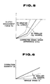
- Fig. 6 shows a relationship between the correction quantity Qi and the vehicle speed Vi, employed in this embodiment.
- the correction quantity Qi increases as the vehicle speed increases, and the rate of increase of the correction quantity is decreased as the lateral acceleration Yg increases.
- the control unit 40 determines a control gain Kh in accordance with the reciprocal of the lateral acceleration Yg.
- the control gain Kh is inversely proportional to the lateral acceleration Yg, and determined by using the following equation.
- the control unit 40 determines the desired clutch engagement force Tm by using the control gain Kh and the correctedd wheel speed difference CDVw.
- the control unit 40 of this embodiment holds the desired clutch engagement force equal to zero when the measured wheel speed difference DVw is negative, and when the corrected wheel speed difference CDVw is negative. However, it is possible to increases the clutch engagement force as the absolute value of the measure wheel speed difference increases or to control the clutch engagement force in any known manner in the negative range in which the measured wheel speed difference is smaller than zero.
- the control unit 40 converts the signal representing Tm determined at the step 87, into the solenoid drive current i by using a predetermined Tm-i characteristic table.
- the control unit 40 delivers the dither current i* (for example, i ⁇ 0.1A, 100 Hz), to the solenoid valve 28.
- the measured wheel speed difference DVw which contains a front and rear wheel speed difference DVs due to drive wheel slip, and a front and rear wheel speed difference DVt due to tire diameter difference between the front and rear wheels, as shown in Fig. 7.
- the front tire diameter is slightly greater than the rear tire diameter.
- the wheel speed difference DVt due to tire diameter difference increases as the vehicle speed increases, as shown in Fig. 7.
- the control system of the embodiment subtracts the correction quantity Qi increasing with the vehicle speed, from the measured wheel speed difference DVw, and employs, as the input to the controller element, the corrected wheel speed difference CDVw which is the result of the subtraction.
- the correction quantity Qi corresponds to the wheel speed difference DVt due to tire diameter difference
- the corrected wheel speed difference CDVw becomes approximately equal to the wheel speed difference DVs due to drive wheel slip.
- the control system of the invention increases the clutch engagement force of the torque distributing transfer clutch adequately in accordance with the drive wheel slip by increasing the magnitude of the control signal in accordance with the corrected wheel speed difference, and by so doing prevents an excess in the clutch engagement force due to the tire diameter difference between the front and rear wheeels.
- the control system of the invention holds the clutch engagement force Tm relatively low even in a high vehicle speed range. Therefore, the control system of the invention can prevent unpleasant up-and-down vibrations and severe clutch slippage resulting in increase in the temperature of the differential oil.
- the control system of the embodiment determines the correction quantity Qi by multiplying the vehicle speed Vi by the proportionality factor Ki which decreases as the lateral acceleration Yg increases, and thereby decreases the correction quantity Qi as the lateral acceleration Yg increases.
- Ki proportionality factor
- a vehicle body roll during cornering weakens the feeling to vibrations, so that the up-and-down vibrations are not so annoying, and the cornering operation does not continue long time, so that the temperature of the differential oil is not increaed too much.
- the control system of this embodiment decreases the correction quantity Qi with increase of the lateral acceleration Yg, as shown in Fig. 6, and thereby refrains from correcting the measured wheel speed difference during a cornering operation.
- control system of the embodiment efficiently prevents the undesired effect of tight corner braking on a high friction coefficient road by decreasing the control gain Kh with increase in the lateral acceleration, and minimizes the drive wheel slip on a low friction coefficient road by increasing the control gain Kh with decrease in the lateral acceleration.
- the present invention is applicable to a 4WD vehicle in which the front wheels are the primary drive wheels, and the rear wheels are the secondary drive wheels.
Landscapes
- Engineering & Computer Science (AREA)
- Chemical & Material Sciences (AREA)
- Combustion & Propulsion (AREA)
- Transportation (AREA)
- Mechanical Engineering (AREA)
- Arrangement And Driving Of Transmission Devices (AREA)
Applications Claiming Priority (2)
| Application Number | Priority Date | Filing Date | Title |
|---|---|---|---|
| JP99745/89 | 1989-04-19 | ||
| JP1099745A JPH0794207B2 (ja) | 1989-04-19 | 1989-04-19 | 四輪駆動車の駆動力配分制御装置 |
Publications (3)
| Publication Number | Publication Date |
|---|---|
| EP0393596A2 true EP0393596A2 (de) | 1990-10-24 |
| EP0393596A3 EP0393596A3 (de) | 1991-03-13 |
| EP0393596B1 EP0393596B1 (de) | 1996-02-28 |
Family
ID=14255549
Family Applications (1)
| Application Number | Title | Priority Date | Filing Date |
|---|---|---|---|
| EP90107276A Expired - Lifetime EP0393596B1 (de) | 1989-04-19 | 1990-04-17 | Vorrichtung zum Steuern der Drehmomentverteilung für ein Fahrzeug mit Allradantrieb |
Country Status (4)
| Country | Link |
|---|---|
| US (1) | US5060747A (de) |
| EP (1) | EP0393596B1 (de) |
| JP (1) | JPH0794207B2 (de) |
| DE (1) | DE69025487T2 (de) |
Cited By (8)
| Publication number | Priority date | Publication date | Assignee | Title |
|---|---|---|---|---|
| GB2239921A (en) * | 1989-11-15 | 1991-07-17 | Honda Motor Co Ltd | Power transmission apparatus for a four-wheel drive vehicle |
| GB2295872A (en) * | 1994-12-09 | 1996-06-12 | Ford Motor Co | Four-wheel drive transfer case control compensates for differences in effective wheel diameter |
| EP0799740A3 (de) * | 1996-04-06 | 1999-05-19 | Volkswagen Aktiengesellschaft | Verfahren zum Steuern einer steuerbaren Kupplung eines Kraftfahrzeuges mit Vierradantrieb |
| US5954778A (en) * | 1996-11-26 | 1999-09-21 | Ford Global Technologies, Inc. | Four-wheel drive transfer case controller with torque decrement strategy |
| US5979584A (en) * | 1997-07-25 | 1999-11-09 | Ford Global Technologies, Inc. | Four-wheel drive transfer case controller |
| US6047231A (en) * | 1997-06-06 | 2000-04-04 | Ford Global Technologies, Inc. | Four wheel drive transfer case controller compatible with a spare tire |
| EP1188597A3 (de) * | 2000-09-19 | 2004-05-19 | Nissan Motor Co., Ltd. | Front/ Heck- Drehmomentverteilungs- Steuerungssystem und -verfahren für vierradgetriebenes Fahrzeug |
| WO2004058532A1 (de) * | 2002-12-20 | 2004-07-15 | Bayerische Motoren Werke Aktiengesellschaft | Verfahren zum steuern einer schaltbaren kupplung in einem antriebsstrang eines kraftfahrzeugs mit vierradantrieb |
Families Citing this family (39)
| Publication number | Priority date | Publication date | Assignee | Title |
|---|---|---|---|---|
| NL9000860A (nl) * | 1990-04-12 | 1991-11-01 | Doornes Transmissie Bv | Elektronisch geregelde continu variabele transmissie. |
| JP3221873B2 (ja) * | 1990-04-20 | 2001-10-22 | マツダ株式会社 | 4輪駆動車のトルク配分制御装置 |
| JP2639173B2 (ja) * | 1990-04-20 | 1997-08-06 | 日産自動車株式会社 | 車両用差動制限制御装置 |
| US5265020A (en) * | 1990-04-20 | 1993-11-23 | Mazda Motor Corporation | Torque distribution control apparatus for four wheel drive |
| US5164903A (en) * | 1990-09-07 | 1992-11-17 | General Motors Corporation | Electronic control of tractive force proportioning for a class of four wheel drive vehicles |
| JP2833199B2 (ja) * | 1990-11-20 | 1998-12-09 | 日産自動車株式会社 | トルク配分制御装置 |
| JPH04283665A (ja) * | 1991-03-12 | 1992-10-08 | Sumitomo Electric Ind Ltd | 車輪速度補正装置 |
| US5301768A (en) * | 1992-05-04 | 1994-04-12 | Aisin Aw Co., Ltd. | Four-wheel drive torque transfer mechanism |
| JP2768134B2 (ja) * | 1992-05-20 | 1998-06-25 | 日産自動車株式会社 | 四輪駆動車の駆動力配分制御装置 |
| JP2903867B2 (ja) * | 1992-06-08 | 1999-06-14 | 日産自動車株式会社 | 四輪駆動車の駆動力配分制御装置 |
| US5407024A (en) * | 1992-06-24 | 1995-04-18 | Borg-Warner Automotive, Inc. | On demand vehicle drive system |
| US6000488A (en) * | 1992-06-24 | 1999-12-14 | Borg-Warner Automotive, Inc. | Motor vehicle transfer case |
| DE4222159A1 (de) * | 1992-07-06 | 1994-01-13 | Bosch Gmbh Robert | Antriebsschlupfregelsystem |
| US5802491A (en) * | 1992-09-10 | 1998-09-01 | Robert Bosch Gmbh | Motor vehicle control system and method |
| JP2914040B2 (ja) * | 1992-09-22 | 1999-06-28 | 日産自動車株式会社 | 四輪駆動車の駆動力配分制御装置 |
| JP3407359B2 (ja) * | 1993-11-05 | 2003-05-19 | 住友電気工業株式会社 | 車輪速度検出装置 |
| JP3301183B2 (ja) * | 1993-11-24 | 2002-07-15 | 日産自動車株式会社 | 車両の前後輪間駆動力配分制御装置 |
| US5492194A (en) * | 1993-12-23 | 1996-02-20 | Borg-Warner Automotive, Inc. | On demand vehicle drive system |
| JP2990413B2 (ja) * | 1994-12-12 | 1999-12-13 | 本田技研工業株式会社 | 車両の車輪速度補正装置 |
| JP3427529B2 (ja) * | 1994-12-26 | 2003-07-22 | 日産自動車株式会社 | 四輪駆動車の駆動力分配制御装置 |
| JP3853858B2 (ja) * | 1995-05-24 | 2006-12-06 | 株式会社デンソー | 自動変速機の油圧制御装置 |
| US5704444A (en) * | 1995-12-11 | 1998-01-06 | Borg-Warner Automotive, Inc. | Adaptive vehicle drive system for extreme operating conditioning |
| KR980010679A (ko) * | 1996-03-29 | 1998-04-30 | 헨리 D.G 웰레스 | 차량의 제어방법 및 그 장치 |
| DE19635809A1 (de) * | 1996-09-04 | 1998-03-05 | Bayerische Motoren Werke Ag | Verfahren und Vorrichtung zur Verbesserung der Fahrstabilität im Schubbetrieb |
| JP3299682B2 (ja) * | 1997-02-27 | 2002-07-08 | 住友電気工業株式会社 | 初期補正係数演算装置 |
| EP1152938A1 (de) * | 1999-12-08 | 2001-11-14 | Robert Bosch Gmbh | Verfahren und vorrichtung zur einstellung der brems- und/oder antriebswirkung an den rädern eines kraftfahrzeugs |
| DE19963651C1 (de) * | 1999-12-30 | 2001-09-13 | Gkn Viscodrive Gmbh | Viscokupplung mit symmetrischem Freilauf |
| US6353399B1 (en) | 2000-10-11 | 2002-03-05 | Ford Global Technologies, Inc. | Robust encoding scheme for a shift motor encoder assembly and a system using the same |
| JP4223255B2 (ja) * | 2002-09-24 | 2009-02-12 | 富士重工業株式会社 | 4輪駆動車のスリップ制御装置 |
| DE10333650A1 (de) * | 2003-07-24 | 2005-02-24 | Bayerische Motoren Werke Ag | Steuersystem für ein zumindest zeitweise vierradgetriebenes Kraftfahrzeug |
| DE10333654B4 (de) * | 2003-07-24 | 2005-09-29 | Bayerische Motoren Werke Ag | Steuervorrichtung für ein zumindest zeitweise vierradgetriebenes Kraftfahrzeug |
| US7630812B2 (en) * | 2004-02-09 | 2009-12-08 | Ford Global Technologies, Llc | Method and system for controlling a transfer case clutch to protect against excessive heat |
| US7363118B2 (en) * | 2004-08-02 | 2008-04-22 | Volvo Trucks North America, Inc. | Methods and apparatus for reducing vehicle tire wear |
| DE102007038151A1 (de) * | 2007-08-13 | 2009-02-19 | Magna Powertrain Ag & Co Kg | Verfahren zum Nachjustieren eines Aktuators einer Allradkupplung |
| US8098054B2 (en) | 2007-10-10 | 2012-01-17 | John Alexander Verschuur | Optimal load controller method and device |
| DE102008000304B4 (de) * | 2008-02-15 | 2017-09-14 | Zf Friedrichshafen Ag | Verfahren zum Betreiben einer Ventileinrichtung einer Getriebeeinrichtung |
| US10065501B2 (en) | 2012-09-05 | 2018-09-04 | Magna Powertrain Ag & Co Kg | Control system for an all-wheel clutch |
| JP6212917B2 (ja) * | 2013-04-15 | 2017-10-18 | 日産自動車株式会社 | 駆動力配分装置 |
| JP6122757B2 (ja) | 2013-10-17 | 2017-04-26 | 本田技研工業株式会社 | 車両の駆動力配分制御装置 |
Family Cites Families (14)
| Publication number | Priority date | Publication date | Assignee | Title |
|---|---|---|---|---|
| JPS58180324A (ja) * | 1982-04-14 | 1983-10-21 | Fuji Heavy Ind Ltd | 4輪駆動車の切換制御装置 |
| DE3608059C1 (en) * | 1984-10-12 | 1987-07-09 | Porsche Ag | Arrangement for controlling the power transmission of a four-wheel drive vehicle |
| JPS61169326A (ja) * | 1985-01-21 | 1986-07-31 | Nissan Motor Co Ltd | 4輪駆動車の駆動力配分制御装置 |
| US4757870A (en) * | 1985-02-20 | 1988-07-19 | Nissan Motor Co., Ltd. | Four wheel drive system having driving force distribution control responsive to front and rear wheel speed difference |
| JPS6231529A (ja) * | 1985-08-05 | 1987-02-10 | Nissan Motor Co Ltd | 4輪駆動車の駆動力配分制御装置 |
| DE3631180A1 (de) * | 1985-09-13 | 1987-04-02 | Nissan Motor | Steuersystem fuer die verteilung des antriebsdrehmoments bei einem 4-rad-antrieb fuer ein fahrzeug |
| JP2518228B2 (ja) * | 1986-09-29 | 1996-07-24 | トヨタ自動車株式会社 | 四輪駆動装置の制御方法 |
| JPH0635261B2 (ja) * | 1986-12-03 | 1994-05-11 | 日産自動車株式会社 | 四輪駆動車の駆動力配分制御装置 |
| JP2507468B2 (ja) * | 1987-08-31 | 1996-06-12 | 日産自動車株式会社 | 四輪駆動車の駆動力配分制御装置 |
| JPH0729555B2 (ja) * | 1987-10-14 | 1995-04-05 | 日産自動車株式会社 | 四輪駆動車の駆動力配分制御装置 |
| JP2528485B2 (ja) * | 1987-11-30 | 1996-08-28 | 日産自動車株式会社 | 四輪駆動車の駆動力配分制御装置 |
| JP2528484B2 (ja) * | 1987-11-30 | 1996-08-28 | 日産自動車株式会社 | 四輪駆動車の駆動力配分制御装置 |
| JP2628882B2 (ja) * | 1988-03-05 | 1997-07-09 | マツダ株式会社 | 4輪駆動車の伝達トルク制御装置 |
| DE3811214C2 (de) * | 1988-04-02 | 1994-04-21 | Porsche Ag | Anordnung zur Steuerung der Kraftübertragung auf wenigstens zwei Achsen eines Kraftfahrzeuges |
-
1989
- 1989-04-19 JP JP1099745A patent/JPH0794207B2/ja not_active Expired - Lifetime
-
1990
- 1990-04-02 US US07/502,684 patent/US5060747A/en not_active Expired - Lifetime
- 1990-04-17 EP EP90107276A patent/EP0393596B1/de not_active Expired - Lifetime
- 1990-04-17 DE DE69025487T patent/DE69025487T2/de not_active Expired - Lifetime
Cited By (13)
| Publication number | Priority date | Publication date | Assignee | Title |
|---|---|---|---|---|
| GB2239921A (en) * | 1989-11-15 | 1991-07-17 | Honda Motor Co Ltd | Power transmission apparatus for a four-wheel drive vehicle |
| GB2239921B (en) * | 1989-11-15 | 1993-07-21 | Honda Motor Co Ltd | Power transmission apparatus for a four-wheel drive vehicle |
| GB2295872A (en) * | 1994-12-09 | 1996-06-12 | Ford Motor Co | Four-wheel drive transfer case control compensates for differences in effective wheel diameter |
| GB2295872B (en) * | 1994-12-09 | 1998-04-22 | Ford Motor Co | A four-wheel drive transfer case controller |
| US5809443A (en) * | 1994-12-09 | 1998-09-15 | Ford Motor Company | Four-wheel drive transfer case controller with compensation for tires with different diameters |
| EP0799740A3 (de) * | 1996-04-06 | 1999-05-19 | Volkswagen Aktiengesellschaft | Verfahren zum Steuern einer steuerbaren Kupplung eines Kraftfahrzeuges mit Vierradantrieb |
| US5954778A (en) * | 1996-11-26 | 1999-09-21 | Ford Global Technologies, Inc. | Four-wheel drive transfer case controller with torque decrement strategy |
| US6047231A (en) * | 1997-06-06 | 2000-04-04 | Ford Global Technologies, Inc. | Four wheel drive transfer case controller compatible with a spare tire |
| US5979584A (en) * | 1997-07-25 | 1999-11-09 | Ford Global Technologies, Inc. | Four-wheel drive transfer case controller |
| EP1188597A3 (de) * | 2000-09-19 | 2004-05-19 | Nissan Motor Co., Ltd. | Front/ Heck- Drehmomentverteilungs- Steuerungssystem und -verfahren für vierradgetriebenes Fahrzeug |
| WO2004058532A1 (de) * | 2002-12-20 | 2004-07-15 | Bayerische Motoren Werke Aktiengesellschaft | Verfahren zum steuern einer schaltbaren kupplung in einem antriebsstrang eines kraftfahrzeugs mit vierradantrieb |
| US7143855B2 (en) | 2002-12-20 | 2006-12-05 | Bayerische Motoren Werke Aktiengesellschaft | Method for controlling a shiftable clutch in the drive train of a 4-wheel drive motor vehicle |
| CN100360335C (zh) * | 2002-12-20 | 2008-01-09 | 宝马股份公司 | 用于控制在四轮驱动汽车传动系中的可切换离合器的方法 |
Also Published As
| Publication number | Publication date |
|---|---|
| JPH02279427A (ja) | 1990-11-15 |
| US5060747A (en) | 1991-10-29 |
| DE69025487D1 (de) | 1996-04-04 |
| EP0393596A3 (de) | 1991-03-13 |
| JPH0794207B2 (ja) | 1995-10-11 |
| EP0393596B1 (de) | 1996-02-28 |
| DE69025487T2 (de) | 1996-07-11 |
Similar Documents
| Publication | Publication Date | Title |
|---|---|---|
| EP0393596B1 (de) | Vorrichtung zum Steuern der Drehmomentverteilung für ein Fahrzeug mit Allradantrieb | |
| US4986388A (en) | Driving force distribution control system for 4wd vehicle | |
| US5010974A (en) | 4WD vehicle with driving force distribution control | |
| US5461568A (en) | Torque split control apparatus | |
| US6575261B2 (en) | Drive-force distribution controller | |
| EP1232900B1 (de) | Verfahren und Vorrichtung zum Steuern eines Fahrzeugs mit Allradantrieb | |
| JPH02171330A (ja) | 四輪駆動車の駆動力配分制御装置 | |
| US6145614A (en) | Four-wheel drive vehicle having differential-limiting control | |
| EP0313371B1 (de) | Steuersystem zum Verteilen der Antriebskraft für vierradangetriebene Kraftfahrzeuge | |
| US10889290B2 (en) | Control apparatus for four-wheel-drive vehicle | |
| US11285809B2 (en) | Travel control apparatus for four-wheel drive vehicle | |
| JP2646820B2 (ja) | 四輪駆動車の駆動力配分制御装置 | |
| US5752575A (en) | Torque distribution control system in vehicle | |
| JP2770670B2 (ja) | 前後輪と左右輪の駆動力配分総合制御装置 | |
| JPH0740041B2 (ja) | 横加速度センサ出力値補正装置及び四輪駆動車の駆動力配分制御装置 | |
| JPH02278157A (ja) | 横加速度センサ異常検出装置 | |
| JP2507608B2 (ja) | 駆動力配分制御装置 | |
| JPH02267028A (ja) | 四輪駆動車の駆動力配分制御装置 | |
| JPH0752677A (ja) | 差動制限トルク制御装置 | |
| JPH02284069A (ja) | 横加速度センサ出力値補正装置 | |
| JP3409418B2 (ja) | 差動制限トルク制御装置 | |
| JPH0740042B2 (ja) | 前後加速度センサ異常検出装置 | |
| JP2936912B2 (ja) | 四輪駆動車の駆動力配分制御装置 | |
| JPH01121760A (ja) | 車両のコーナリング限界警報装置 | |
| JPH06144066A (ja) | 車両用差動制限制御装置 |
Legal Events
| Date | Code | Title | Description |
|---|---|---|---|
| PUAI | Public reference made under article 153(3) epc to a published international application that has entered the european phase |
Free format text: ORIGINAL CODE: 0009012 |
|
| 17P | Request for examination filed |
Effective date: 19900417 |
|
| AK | Designated contracting states |
Kind code of ref document: A2 Designated state(s): DE FR GB |
|
| PUAL | Search report despatched |
Free format text: ORIGINAL CODE: 0009013 |
|
| AK | Designated contracting states |
Kind code of ref document: A3 Designated state(s): DE FR GB |
|
| 17Q | First examination report despatched |
Effective date: 19921127 |
|
| RBV | Designated contracting states (corrected) |
Designated state(s): DE GB |
|
| GRAA | (expected) grant |
Free format text: ORIGINAL CODE: 0009210 |
|
| AK | Designated contracting states |
Kind code of ref document: B1 Designated state(s): DE GB |
|
| REF | Corresponds to: |
Ref document number: 69025487 Country of ref document: DE Date of ref document: 19960404 |
|
| PLBE | No opposition filed within time limit |
Free format text: ORIGINAL CODE: 0009261 |
|
| STAA | Information on the status of an ep patent application or granted ep patent |
Free format text: STATUS: NO OPPOSITION FILED WITHIN TIME LIMIT |
|
| 26N | No opposition filed | ||
| REG | Reference to a national code |
Ref country code: GB Ref legal event code: IF02 |
|
| PGFP | Annual fee paid to national office [announced via postgrant information from national office to epo] |
Ref country code: DE Payment date: 20090409 Year of fee payment: 20 |
|
| PGFP | Annual fee paid to national office [announced via postgrant information from national office to epo] |
Ref country code: GB Payment date: 20090415 Year of fee payment: 20 |
|
| REG | Reference to a national code |
Ref country code: GB Ref legal event code: PE20 Expiry date: 20100416 |
|
| PG25 | Lapsed in a contracting state [announced via postgrant information from national office to epo] |
Ref country code: GB Free format text: LAPSE BECAUSE OF EXPIRATION OF PROTECTION Effective date: 20100416 |
|
| PG25 | Lapsed in a contracting state [announced via postgrant information from national office to epo] |
Ref country code: DE Free format text: LAPSE BECAUSE OF EXPIRATION OF PROTECTION Effective date: 20100417 |