EP0393733B1 - Single- or polyphase medium-voltage switching device and distribution installation assembled therewith - Google Patents
Single- or polyphase medium-voltage switching device and distribution installation assembled therewith Download PDFInfo
- Publication number
- EP0393733B1 EP0393733B1 EP90200556A EP90200556A EP0393733B1 EP 0393733 B1 EP0393733 B1 EP 0393733B1 EP 90200556 A EP90200556 A EP 90200556A EP 90200556 A EP90200556 A EP 90200556A EP 0393733 B1 EP0393733 B1 EP 0393733B1
- Authority
- EP
- European Patent Office
- Prior art keywords
- container
- housing
- uprights
- bottom wall
- metal
- Prior art date
- Legal status (The legal status is an assumption and is not a legal conclusion. Google has not performed a legal analysis and makes no representation as to the accuracy of the status listed.)
- Expired - Lifetime
Links
- 238000009434 installation Methods 0.000 title claims abstract description 22
- 239000002184 metal Substances 0.000 claims abstract description 21
- 238000009413 insulation Methods 0.000 claims abstract description 10
- 239000007787 solid Substances 0.000 claims abstract description 10
- 238000010276 construction Methods 0.000 claims abstract description 8
- 238000005538 encapsulation Methods 0.000 claims description 8
- 238000007789 sealing Methods 0.000 claims description 2
- 238000005266 casting Methods 0.000 abstract description 16
- 239000011347 resin Substances 0.000 abstract description 16
- 229920005989 resin Polymers 0.000 abstract description 16
- 230000003014 reinforcing effect Effects 0.000 description 4
- 239000004020 conductor Substances 0.000 description 2
- 230000008878 coupling Effects 0.000 description 2
- 238000010168 coupling process Methods 0.000 description 2
- 238000005859 coupling reaction Methods 0.000 description 2
- 238000010616 electrical installation Methods 0.000 description 2
- 239000000463 material Substances 0.000 description 2
- 238000007665 sagging Methods 0.000 description 2
- 230000000694 effects Effects 0.000 description 1
- 239000011810 insulating material Substances 0.000 description 1
- 239000012774 insulation material Substances 0.000 description 1
- 238000011068 loading method Methods 0.000 description 1
- 238000005192 partition Methods 0.000 description 1
Images


Classifications
-
- H—ELECTRICITY
- H02—GENERATION; CONVERSION OR DISTRIBUTION OF ELECTRIC POWER
- H02B—BOARDS, SUBSTATIONS OR SWITCHING ARRANGEMENTS FOR THE SUPPLY OR DISTRIBUTION OF ELECTRIC POWER
- H02B13/00—Arrangement of switchgear in which switches are enclosed in, or structurally associated with, a casing, e.g. cubicle
- H02B13/02—Arrangement of switchgear in which switches are enclosed in, or structurally associated with, a casing, e.g. cubicle with metal casing
- H02B13/035—Gas-insulated switchgear
- H02B13/0354—Gas-insulated switchgear comprising a vacuum switch
-
- H—ELECTRICITY
- H02—GENERATION; CONVERSION OR DISTRIBUTION OF ELECTRIC POWER
- H02B—BOARDS, SUBSTATIONS OR SWITCHING ARRANGEMENTS FOR THE SUPPLY OR DISTRIBUTION OF ELECTRIC POWER
- H02B11/00—Switchgear having carriage withdrawable for isolation
- H02B11/26—Arrangements of fuses, resistors, voltage arresters or the like
Definitions
- the invention relates to a single- or polyphase medium-voltage switching device comprising a metal housing in which one or more switches provided with an actuating mechanism are accommodated, solid insulation being used for insulating and suspending the switches from the metal housing, said housing being constructed from an essentially rectangular metal container having side walls, a bottom wall and uprights fitted near the corner points of the bottom wall, in which container the actuating mechanism of the switching device is accommodated, the housing being closed by means of metal plates attached to the uprights and the container being closed by means of a metal top plate.
- a switching device of this type in particular a polyphase medium-voltage switching device, is described by US-A-2,362,798.
- the switches or circuit breakers of each phase are, in one embodiment, suspended and insulated from the top wall of the housing.
- the circuit-breaker operating and controlling means are located in the container positioned beneath the circuit breakers.
- the circuit breakers are supported on and insulated from the bottom wall of the housing, the container accommodating the circuit breaker actuating means being positioned above the circuit breakers.
- the individual circuit breakers are enclosed by a solid insulating material.
- a mechanically rigid housing is required in order to prevent, inter alia, the casting resin from being subjected to undesirable torsion stresses.
- Such mechanical loadings cause cracks and breakage of the casting resin, as a consequence of which the grade of insulation is reduced and the switching device no longer meets its specifications.
- Housings known in practice for accomodating components insulated with casting resin usually comprise a frame provided with a web of connecting rods, partitions etc. in order to achieve the desired mechanical rigidity.
- One of the consequences of these measures is that, in addition to its complexity, the total quantity of material required and, consequently, also the weight of the overall housing structure also increases appreciably, as does the time which is needed to assemble the housing.
- the reinforcing structure makes a direct coupling of a plurality of housings difficult, if not impossible.
- the object of the invention is therefore to provide a single or polyphase medium-voltage switching device having a relatively simple housing structure, such as known from US-A-2,362,798, which is adequate, in particular for accommodating electrical components insulated with casting resin.
- the invention makes use of the fact that the actuating mechanism of the switching installation, which mechanism comprises, in general, a plurality of levers, locking pawls and the like which act on one another, should be accommodated in a mechanically rigid container in order to guarantee its reliable functioning.
- said container is now used as the base for mounting the solid-insulated components.
- attachment to the bottom plate of the container is in principle adequate, which container should per se be of a mechanically rigid construction, if only for the purpose of the reliable functioning of the actuating mechanism.
- a stable and contact-safe housing is obtained by subsequently fitting side, rear, front and top plates and, if desired, a bottom plate.
- a housing manufactured in this manner weighs about one third of the weight of the conventional housings. Such a weight saving is advantageous because less difficult requirements are imposed thereby on transportation and lifting devices for transporting and siting such switching devices and also on the foundations needed therefor.
- said further components comprise one or more high-voltage blow-out fuses and one or more cylindrical holders constructed of solid insulation having an opening for receiving a blow-out fuse, each holder being suspended in the housing from said encapsulation in an inclined position such that its receiving opening is situated opposite the bottom wall of the container and is accessible from one side of the housing, the plate of said side being divided into two halves, the half situated near the container being of detachable construction for fitting or removing a blow-out fuse.
- the inclined arrangement of the holders for the blow-out fuses achieves the result that said holders can be suspended as an entity from the encapsulation of the switches and that only half the front plate needs to be removed to fit and remove blow-out fuses, which does not have a disadvantageous effect on the rigidity of the housing.
- Medium-voltage switching devices are generally used in electrical distribution networks for connecting a ring conductor to a transformer. To protect the transformer, a switching device provided with blow-out fuses is then generally required. In order to be able to interrupt the ring conductor from both the one side and the other side, two switching devices are used which are provided essentially with the switches alone. As a consequence of the relatively simple housing construction according to the invention, which is uniform in terms of dimensions, two or more such switching devices can be combined in a simple manner to form a medium-voltage distribution installation having a desired mechanical rigidity.
- the invention consequently also relates to a medium-voltage distribution installation comprising two or more medium-voltage switching devices as described above, characterized in that the separate switching devices are arranged adjacent to one another, the containers and uprights situated next to one another being mutually coupled and provided at least in pairs with a common top plate.
- the uniform housing discussed above offers many application possibilities, in particular for accommodating the components needed in medium-voltage switching and distribution installations, such as switches, fuses, transformers and the like, especially provided with casting resin insulation.
- the possibility of coupling switching devices being desirable, for example, in connection with the expected extensions of electrical installations.
- the invention therefore also relates to a housing for use with a switching device or a medium-voltage distribution installation, comprising at least one essentially rectangular container having side walls and a bottom wall provided with feed-through openings for the actuating mechanism of one or more electrical switching or safety arrangements to be accommodated in the housing, said at least one container being provided with uprights near the corner points of the bottom wall, having metal plates attached to the uprights for sealing off the space bounded thereby beneath the bottom wall of the at least one container and having a top plate which seals off the least one container, characterized by the bottom wall of the at least one container having means for suspending switches and further components, the top plate extending at least over two containers in the case of a plurality of containers arranged adjacently to one another.
- the embodiment, shown diagrammatically in section in Figure 1, of a medium-voltage switching device according to the invention is suitable for 12-24 kV high-voltage installations.
- the switching installation is provided with an actuating mechanism 1 comprising diverse levers, locking pawls etc., which mechanism is accommodated in a metal container 2 which is provided with side walls 3, 4, 5, 6 and a bottom wall 7.
- the walls 3-7 of the container 2 have a thickness such that a mechanically rigid construction is obtained, and this is necessary in order to be able to guarantee a reliable operation of the actuating mechanism.
- a vacuum contact breaker 8 Provided in the bottom wall 7 of the container 2 are feed-through openings which lead to, respectively, a vacuum contact breaker 8, a selection switch 9 and a holder 10 for a blow-out fuse 11.
- the vacuum contact breaker 8 and the selection switch 9, together with the rail system 12 coupled thereto, are surrounded by a casting resin encapsulation 13 as a structural entity which is suspended with the aid of bolts 14 from the bottom wall 7 of the container.
- the holder 10 for a blow-out fuse 11 can optionally be present and coupled to the vacuum contact breaker 8, and is consequently provided with its own casting resin encapsulation.
- the container 2 is provided at its corners with uprights 15 such as L, H, U sections, tubes or the like. Although the uprights 15 permit a certain rotation with respect to the longitudinal axis of the housing, this does not result in any undesirable torsion stresses in the casting resin insulation because, as a consequence of the rigid construction of the container 2, the bottom wall 7 forms a stable supporting surface.
- uprights 15 such as L, H, U sections, tubes or the like.
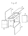
- Figure 2 shows the housing according to the invention diagrammatically and in perspective, and from this it can clearly be seen that the container 2 for the switching mechanism extends at the top of the housing over the entire transverse surface thereof.
- metal plates 16 of various dimensions which are attached to the uprights 15 are provided.
- a separate top plate 17 is provided for the container 2.
- the holder 10 for the blow-out fuse 11 with its receiving opening 18 is arranged at an angle in the direction of the bottom plate 7 of the container 2 and is accessible from the actuation side 19 of the switching device.
- the advantage of this arrangement of the holder 10 at an angle lies in the fact that, to remove or fit a blow-out fuse in the holder 10, only one section of the plate needs to be removed at the actuation side 19 so that the other parts of the switching device remain protected in a contact-safe manner.
- the arrangement of the holder 10 at an angle furthermore has the advantage that relatively little space is needed outside the housing of the switching device for manoeuvring with a blow-out fuse 11. This last feature makes this switching device particularly suitable for use in small distribution stations, transformer housings etc.
- the angle at which the holder 11 is arranged is chosen in a manner such that the replacement of a blow-out fuse 11 can be carried out within the overall height of the housing by means of the gripping device 20 which is provided therefor and which also serves as a cap for connecting a terminal electrode of the blow-out fuse 11 to the other parts of the switching device.
- the housing according to the invention is eminently suitable for a modular system with which two or more switching devices can be combined to form a single distribution installation.
- Figures 3 and 4 diagrammatically show the two most important embodiments of medium-voltage switching devices for constructing such a distribution installation.
- Figure 3 shows a module comprising a combination of a selection switch 9 and a contact breaker 8, to which a blow-out fuse 11 is added in the module according to Figure 4. Both modules have uniform dimensions.
- the associated electrical circuits are drawn in single-phase form, it will be obvious to a person skilled in the art that each module is provided with three circuits as shown in, for example, a three-phase electrical installation.
- Figure 5 shows a typical construction of a medium-voltage distribution installation for use in a ring mains.
- the distribution installation is constructed from two modules as shown in Figure 3 and one module as shown in Figure 4 which leads, for example, to a transformer.
- the modules arranged next to one another are provided with a common top plate 17'.
- housing the bottom surfaces 7 of the separate modules form a torsion-free reference surface.
- the back wall of the distribution installation i.e. the wall opposite the actuation side 19 of the switching devices, may also be constructed as a common plate (not shown).
- FIG 6 shows diagrammatically another type of distribution installation constructed from modules having a housing according to the invention.
- the centremost module comprises a so-called test section in which transformers 21, 22 are incorporated for test purposes.
- the top plates 17', 17'' extend over three or two, respectively, switching devices arranged next to one another.
- the backwall of the distribution installation may also be constructed of plates extending over two or more devices (not shown).
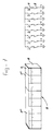
- Figure 7 shows an extended distribution installation constructed from eight modules according to Figure 3.
- a top plate 17''' which extend over five modules
- a top plate 17'' which extends over two modules
- the invention provides modular medium-voltage devices having a relatively simple housing structure with which distribution installations can be constructed with a mechanically adequate rigid structure permitting the use of components insulated with casting resin. It is obvious to the person skilled in the art that a large number of combinations is possible in which, instead of being arranged side-by-side as shown, the separate modules may also be arranged, for example, with their backs to one another and also provided with top plates extending over a plurality of modules to provide a desired mechanically rigid housing.
Landscapes
- Engineering & Computer Science (AREA)
- Power Engineering (AREA)
- Patch Boards (AREA)
- Gas-Insulated Switchgears (AREA)
- Rectifiers (AREA)
- Supply And Distribution Of Alternating Current (AREA)
- Generation Of Surge Voltage And Current (AREA)
- Switch Cases, Indication, And Locking (AREA)
Applications Claiming Priority (2)
| Application Number | Priority Date | Filing Date | Title |
|---|---|---|---|
| NL8900709A NL8900709A (nl) | 1989-03-22 | 1989-03-22 | Een of meerfasige middenspannings-schakelinrichting en een hiermee samengestelde middenspannings-verdeelinrichting. |
| NL8900709 | 1989-03-22 |
Publications (2)
| Publication Number | Publication Date |
|---|---|
| EP0393733A1 EP0393733A1 (en) | 1990-10-24 |
| EP0393733B1 true EP0393733B1 (en) | 1994-07-20 |
Family
ID=19854340
Family Applications (1)
| Application Number | Title | Priority Date | Filing Date |
|---|---|---|---|
| EP90200556A Expired - Lifetime EP0393733B1 (en) | 1989-03-22 | 1990-03-08 | Single- or polyphase medium-voltage switching device and distribution installation assembled therewith |
Country Status (9)
| Country | Link |
|---|---|
| EP (1) | EP0393733B1 (da) |
| AT (1) | ATE108956T1 (da) |
| AU (1) | AU618458B2 (da) |
| DE (1) | DE69010741T2 (da) |
| DK (1) | DK0393733T3 (da) |
| ES (1) | ES2059988T3 (da) |
| IE (1) | IE65645B1 (da) |
| NL (1) | NL8900709A (da) |
| NZ (1) | NZ233016A (da) |
Cited By (1)
| Publication number | Priority date | Publication date | Assignee | Title |
|---|---|---|---|---|
| JP2007104754A (ja) * | 2005-09-30 | 2007-04-19 | Mitsubishi Electric Corp | ガス絶縁開閉装置の絶縁ガス封入方法及びガス絶縁開閉装置の製造方法 |
Families Citing this family (6)
| Publication number | Priority date | Publication date | Assignee | Title |
|---|---|---|---|---|
| NL1017797C2 (nl) * | 2001-04-09 | 2002-10-10 | Holec Holland Nv | Een- of meerfasenschakelinrichting in een omhullende behuizing. |
| WO2008006915A1 (es) | 2006-07-13 | 2008-01-17 | Ormazabal Y Cia, S.A. | Equipo eléctrico encapsulado modular para redes de distribución eléctrica |
| EP2075817A1 (en) | 2007-12-27 | 2009-07-01 | Ormazabal Y Cia., S.A. | Actuation transmission system for electrical equipment |
| WO2020012599A1 (ja) * | 2018-07-12 | 2020-01-16 | 三菱電機株式会社 | スイッチギヤ |
| ES1276579Y (es) | 2021-03-23 | 2021-11-15 | Ormazabal Y Cia S L U | Aparamenta eléctrica aislada en gas para redes de distribución eléctrica de media y alta tensión |
| ES1295907Y (es) | 2022-06-15 | 2023-03-14 | Ormazabal Y Cia S L U | Dispositivo de interconexión eléctrica |
Family Cites Families (5)
| Publication number | Priority date | Publication date | Assignee | Title |
|---|---|---|---|---|
| US2362798A (en) * | 1942-06-30 | 1944-11-14 | Gen Electric | Electric switchgear |
| AT217547B (de) * | 1956-04-06 | 1961-10-10 | Calor Emag Elektrizitaets Ag | Schaltanlage für hohe Spannungen |
| DD113829A1 (da) * | 1974-08-07 | 1975-06-20 | ||
| FR2556169B1 (fr) * | 1983-12-01 | 1986-09-05 | Merlin Gerin | Coffret pour appareillage electrique susceptible d'etre assemble lors de l'installation |
| SE448416B (sv) * | 1985-06-28 | 1987-02-16 | Ericsson Telefon Ab L M | Skap for exempelvis elektrisk utrustning |
-
1989
- 1989-03-22 NL NL8900709A patent/NL8900709A/nl not_active Application Discontinuation
-
1990
- 1990-03-08 DE DE69010741T patent/DE69010741T2/de not_active Expired - Fee Related
- 1990-03-08 ES ES90200556T patent/ES2059988T3/es not_active Expired - Lifetime
- 1990-03-08 AT AT90200556T patent/ATE108956T1/de not_active IP Right Cessation
- 1990-03-08 EP EP90200556A patent/EP0393733B1/en not_active Expired - Lifetime
- 1990-03-08 DK DK90200556.0T patent/DK0393733T3/da active
- 1990-03-21 AU AU52059/90A patent/AU618458B2/en not_active Ceased
- 1990-03-21 IE IE104590A patent/IE65645B1/en not_active IP Right Cessation
- 1990-03-21 NZ NZ233016A patent/NZ233016A/en unknown
Cited By (1)
| Publication number | Priority date | Publication date | Assignee | Title |
|---|---|---|---|---|
| JP2007104754A (ja) * | 2005-09-30 | 2007-04-19 | Mitsubishi Electric Corp | ガス絶縁開閉装置の絶縁ガス封入方法及びガス絶縁開閉装置の製造方法 |
Also Published As
| Publication number | Publication date |
|---|---|
| NL8900709A (nl) | 1990-10-16 |
| DE69010741D1 (de) | 1994-08-25 |
| NZ233016A (en) | 1993-01-27 |
| IE901045L (en) | 1990-09-22 |
| EP0393733A1 (en) | 1990-10-24 |
| AU5205990A (en) | 1990-09-27 |
| AU618458B2 (en) | 1991-12-19 |
| IE901045A1 (en) | 1991-06-19 |
| DK0393733T3 (da) | 1994-10-31 |
| DE69010741T2 (de) | 1994-10-27 |
| IE65645B1 (en) | 1995-11-15 |
| ATE108956T1 (de) | 1994-08-15 |
| ES2059988T3 (es) | 1994-11-16 |
Similar Documents
| Publication | Publication Date | Title |
|---|---|---|
| RU2344529C2 (ru) | Газоизолированное распределительное устройство с закрытыми ячейками | |
| US20120138575A1 (en) | Electric circuit breaker and switchgear panel with circuit breaker | |
| US3793562A (en) | With insulating battle supporting terminal conductors | |
| CA2147085A1 (en) | Metal-enclosed gas-filled switchgear units | |
| EP0393733B1 (en) | Single- or polyphase medium-voltage switching device and distribution installation assembled therewith | |
| US6459569B1 (en) | Switchgear | |
| US3746817A (en) | Metal-enclosed switchgear | |
| JPH08340610A (ja) | ガス絶縁開閉装置 | |
| EP0428220B1 (en) | Metal-encased modular mediumvoltage distribution system | |
| US4342067A (en) | Electric power substation for use at very high voltages | |
| JPH04133218A (ja) | 負荷開閉設備 | |
| JPS6035431A (ja) | ガス絶縁開閉装置 | |
| JPH0522815A (ja) | ガス絶縁開閉装置 | |
| EP0430446A1 (en) | Enclosures for electrical switchgear | |
| JPH07193925A (ja) | ガス絶縁開閉装置 | |
| JPH076651Y2 (ja) | ガス絶縁開閉装置 | |
| JPS6149884B2 (da) | ||
| JP2762654B2 (ja) | ガス絶縁開閉装置 | |
| JPS6013208Y2 (ja) | 閉鎖配電盤 | |
| JPS6124886B2 (da) | ||
| JPS60187217A (ja) | ガス絶縁開閉装置 | |
| JP2590659Y2 (ja) | ガス絶縁開閉装置 | |
| JPS61167307A (ja) | ガス絶縁開閉装置 | |
| JPH0620328B2 (ja) | ガス絶縁開閉装置 | |
| JPH06303708A (ja) | ガス絶縁開閉装置 |
Legal Events
| Date | Code | Title | Description |
|---|---|---|---|
| PUAI | Public reference made under article 153(3) epc to a published international application that has entered the european phase |
Free format text: ORIGINAL CODE: 0009012 |
|
| AK | Designated contracting states |
Kind code of ref document: A1 Designated state(s): AT BE CH DE DK ES FR GB GR IT LI LU NL SE |
|
| 17P | Request for examination filed |
Effective date: 19901122 |
|
| 17Q | First examination report despatched |
Effective date: 19921221 |
|
| GRAA | (expected) grant |
Free format text: ORIGINAL CODE: 0009210 |
|
| AK | Designated contracting states |
Kind code of ref document: B1 Designated state(s): AT BE CH DE DK ES FR GB GR IT LI LU NL SE |
|
| REF | Corresponds to: |
Ref document number: 108956 Country of ref document: AT Date of ref document: 19940815 Kind code of ref document: T |
|
| REF | Corresponds to: |
Ref document number: 69010741 Country of ref document: DE Date of ref document: 19940825 |
|
| ET | Fr: translation filed | ||
| ITF | It: translation for a ep patent filed | ||
| REG | Reference to a national code |
Ref country code: DK Ref legal event code: T3 |
|
| REG | Reference to a national code |
Ref country code: ES Ref legal event code: FG2A Ref document number: 2059988 Country of ref document: ES Kind code of ref document: T3 |
|
| REG | Reference to a national code |
Ref country code: GR Ref legal event code: FG4A Free format text: 3013208 |
|
| EAL | Se: european patent in force in sweden |
Ref document number: 90200556.0 |
|
| PLBE | No opposition filed within time limit |
Free format text: ORIGINAL CODE: 0009261 |
|
| STAA | Information on the status of an ep patent application or granted ep patent |
Free format text: STATUS: NO OPPOSITION FILED WITHIN TIME LIMIT |
|
| 26N | No opposition filed | ||
| REG | Reference to a national code |
Ref country code: CH Ref legal event code: NV Representative=s name: PATENTANWALTSBUREAU R. A. MASPOLI |
|
| REG | Reference to a national code |
Ref country code: CH Ref legal event code: PUE Owner name: HOLEC SYSTEMEN & COMPONENTEN B.V. TRANSFER- HOLEC |
|
| NLS | Nl: assignments of ep-patents |
Owner name: HOLEC HOLLAND N.V. |
|
| REG | Reference to a national code |
Ref country code: GB Ref legal event code: 732E |
|
| REG | Reference to a national code |
Ref country code: ES Ref legal event code: PC2A |
|
| REG | Reference to a national code |
Ref country code: FR Ref legal event code: TP |
|
| REG | Reference to a national code |
Ref country code: GB Ref legal event code: IF02 |
|
| NLS | Nl: assignments of ep-patents |
Owner name: EATON HOLDING INTERNATIONAL I BV Owner name: EATON ELECTRIC N.V. |
|
| REG | Reference to a national code |
Ref country code: GB Ref legal event code: 732E |
|
| REG | Reference to a national code |
Ref country code: GB Ref legal event code: 732E |
|
| BECA | Be: change of holder's address |
Owner name: *EATON ELECTRIC N.V.EUROPALAAN 202, NL-7559 SC HEN Effective date: 20040610 |
|
| BECH | Be: change of holder |
Owner name: *EATON ELECTRIC N.V.EUROPALAAN 202, NL-7559 SC HEN Effective date: 20040610 |
|
| REG | Reference to a national code |
Ref country code: CH Ref legal event code: PUE Owner name: EATON HOLDING INTERNATIONAL I BV Free format text: HOLEC HOLLAND N.V.#TUINDORPSTRAAT 61#7555 CS HENGELO (NL) -TRANSFER TO- EATON HOLDING INTERNATIONAL I BV#BOEING AVENUE 11#1119 PC SCHIPHOL-RIJK (NL) Ref country code: CH Ref legal event code: PUE Owner name: EATON ELECTRIC N.V. Free format text: EATON HOLDING INTERNATIONAL I BV#BOEING AVENUE 11#1119 PC SCHIPHOL-RIJK (NL) -TRANSFER TO- EATON ELECTRIC N.V.#P.O. BOX 23#7550 AA HENGELO (NL) |
|
| PGFP | Annual fee paid to national office [announced via postgrant information from national office to epo] |
Ref country code: LU Payment date: 20041220 Year of fee payment: 16 |
|
| PGFP | Annual fee paid to national office [announced via postgrant information from national office to epo] |
Ref country code: GR Payment date: 20050118 Year of fee payment: 16 |
|
| PGFP | Annual fee paid to national office [announced via postgrant information from national office to epo] |
Ref country code: GB Payment date: 20050207 Year of fee payment: 16 Ref country code: DK Payment date: 20050207 Year of fee payment: 16 Ref country code: AT Payment date: 20050207 Year of fee payment: 16 |
|
| PGFP | Annual fee paid to national office [announced via postgrant information from national office to epo] |
Ref country code: NL Payment date: 20050209 Year of fee payment: 16 |
|
| PGFP | Annual fee paid to national office [announced via postgrant information from national office to epo] |
Ref country code: FR Payment date: 20050302 Year of fee payment: 16 |
|
| PGFP | Annual fee paid to national office [announced via postgrant information from national office to epo] |
Ref country code: SE Payment date: 20050303 Year of fee payment: 16 |
|
| PGFP | Annual fee paid to national office [announced via postgrant information from national office to epo] |
Ref country code: ES Payment date: 20050314 Year of fee payment: 16 |
|
| PGFP | Annual fee paid to national office [announced via postgrant information from national office to epo] |
Ref country code: CH Payment date: 20050317 Year of fee payment: 16 |
|
| REG | Reference to a national code |
Ref country code: FR Ref legal event code: TP |
|
| PGFP | Annual fee paid to national office [announced via postgrant information from national office to epo] |
Ref country code: DE Payment date: 20050331 Year of fee payment: 16 |
|
| PGFP | Annual fee paid to national office [announced via postgrant information from national office to epo] |
Ref country code: BE Payment date: 20050412 Year of fee payment: 16 |
|
| PG25 | Lapsed in a contracting state [announced via postgrant information from national office to epo] |
Ref country code: GB Free format text: LAPSE BECAUSE OF NON-PAYMENT OF DUE FEES Effective date: 20060308 Ref country code: AT Free format text: LAPSE BECAUSE OF NON-PAYMENT OF DUE FEES Effective date: 20060308 |
|
| PG25 | Lapsed in a contracting state [announced via postgrant information from national office to epo] |
Ref country code: SE Free format text: LAPSE BECAUSE OF NON-PAYMENT OF DUE FEES Effective date: 20060309 Ref country code: ES Free format text: LAPSE BECAUSE OF NON-PAYMENT OF DUE FEES Effective date: 20060309 |
|
| PG25 | Lapsed in a contracting state [announced via postgrant information from national office to epo] |
Ref country code: LU Free format text: LAPSE BECAUSE OF NON-PAYMENT OF DUE FEES Effective date: 20060331 Ref country code: LI Free format text: LAPSE BECAUSE OF NON-PAYMENT OF DUE FEES Effective date: 20060331 Ref country code: DK Free format text: LAPSE BECAUSE OF NON-PAYMENT OF DUE FEES Effective date: 20060331 Ref country code: CH Free format text: LAPSE BECAUSE OF NON-PAYMENT OF DUE FEES Effective date: 20060331 Ref country code: BE Free format text: LAPSE BECAUSE OF NON-PAYMENT OF DUE FEES Effective date: 20060331 |
|
| PGFP | Annual fee paid to national office [announced via postgrant information from national office to epo] |
Ref country code: IT Payment date: 20060331 Year of fee payment: 17 |
|
| PG25 | Lapsed in a contracting state [announced via postgrant information from national office to epo] |
Ref country code: NL Free format text: LAPSE BECAUSE OF NON-PAYMENT OF DUE FEES Effective date: 20061001 |
|
| PG25 | Lapsed in a contracting state [announced via postgrant information from national office to epo] |
Ref country code: DE Free format text: LAPSE BECAUSE OF NON-PAYMENT OF DUE FEES Effective date: 20061003 |
|
| REG | Reference to a national code |
Ref country code: DK Ref legal event code: EBP |
|
| REG | Reference to a national code |
Ref country code: CH Ref legal event code: PL |
|
| EUG | Se: european patent has lapsed | ||
| GBPC | Gb: european patent ceased through non-payment of renewal fee |
Effective date: 20060308 |
|
| NLV4 | Nl: lapsed or anulled due to non-payment of the annual fee |
Effective date: 20061001 |
|
| REG | Reference to a national code |
Ref country code: FR Ref legal event code: ST Effective date: 20061130 |
|
| REG | Reference to a national code |
Ref country code: ES Ref legal event code: FD2A Effective date: 20060309 |
|
| BERE | Be: lapsed |
Owner name: *EATON ELECTRIC N.V. Effective date: 20060331 |
|
| PG25 | Lapsed in a contracting state [announced via postgrant information from national office to epo] |
Ref country code: FR Free format text: LAPSE BECAUSE OF NON-PAYMENT OF DUE FEES Effective date: 20060331 |
|
| PG25 | Lapsed in a contracting state [announced via postgrant information from national office to epo] |
Ref country code: GR Free format text: LAPSE BECAUSE OF NON-PAYMENT OF DUE FEES Effective date: 20061002 |
|
| PG25 | Lapsed in a contracting state [announced via postgrant information from national office to epo] |
Ref country code: IT Free format text: LAPSE BECAUSE OF NON-PAYMENT OF DUE FEES Effective date: 20070308 |