EP0394561A2 - Rouleaux encreurs oléphiles hydrophobes et microporeux - Google Patents
Rouleaux encreurs oléphiles hydrophobes et microporeux Download PDFInfo
- Publication number
- EP0394561A2 EP0394561A2 EP89124065A EP89124065A EP0394561A2 EP 0394561 A2 EP0394561 A2 EP 0394561A2 EP 89124065 A EP89124065 A EP 89124065A EP 89124065 A EP89124065 A EP 89124065A EP 0394561 A2 EP0394561 A2 EP 0394561A2
- Authority
- EP
- European Patent Office
- Prior art keywords
- ink
- coupling agent
- roller
- metering roller
- titanate
- Prior art date
- Legal status (The legal status is an assumption and is not a legal conclusion. Google has not performed a legal analysis and makes no representation as to the accuracy of the status listed.)
- Granted
Links
Images
Classifications
-
- B—PERFORMING OPERATIONS; TRANSPORTING
- B41—PRINTING; LINING MACHINES; TYPEWRITERS; STAMPS
- B41N—PRINTING PLATES OR FOILS; MATERIALS FOR SURFACES USED IN PRINTING MACHINES FOR PRINTING, INKING, DAMPING, OR THE LIKE; PREPARING SUCH SURFACES FOR USE AND CONSERVING THEM
- B41N7/00—Shells for rollers of printing machines
- B41N7/06—Shells for rollers of printing machines for inking rollers
-
- B—PERFORMING OPERATIONS; TRANSPORTING
- B41—PRINTING; LINING MACHINES; TYPEWRITERS; STAMPS
- B41N—PRINTING PLATES OR FOILS; MATERIALS FOR SURFACES USED IN PRINTING MACHINES FOR PRINTING, INKING, DAMPING, OR THE LIKE; PREPARING SUCH SURFACES FOR USE AND CONSERVING THEM
- B41N2207/00—Location or type of the layers in shells for rollers of printing machines
- B41N2207/02—Top layers
-
- B—PERFORMING OPERATIONS; TRANSPORTING
- B41—PRINTING; LINING MACHINES; TYPEWRITERS; STAMPS
- B41N—PRINTING PLATES OR FOILS; MATERIALS FOR SURFACES USED IN PRINTING MACHINES FOR PRINTING, INKING, DAMPING, OR THE LIKE; PREPARING SUCH SURFACES FOR USE AND CONSERVING THEM
- B41N2207/00—Location or type of the layers in shells for rollers of printing machines
- B41N2207/10—Location or type of the layers in shells for rollers of printing machines characterised by inorganic compounds, e.g. pigments
-
- B—PERFORMING OPERATIONS; TRANSPORTING
- B41—PRINTING; LINING MACHINES; TYPEWRITERS; STAMPS
- B41N—PRINTING PLATES OR FOILS; MATERIALS FOR SURFACES USED IN PRINTING MACHINES FOR PRINTING, INKING, DAMPING, OR THE LIKE; PREPARING SUCH SURFACES FOR USE AND CONSERVING THEM
- B41N2207/00—Location or type of the layers in shells for rollers of printing machines
- B41N2207/14—Location or type of the layers in shells for rollers of printing machines characterised by macromolecular organic compounds
-
- Y—GENERAL TAGGING OF NEW TECHNOLOGICAL DEVELOPMENTS; GENERAL TAGGING OF CROSS-SECTIONAL TECHNOLOGIES SPANNING OVER SEVERAL SECTIONS OF THE IPC; TECHNICAL SUBJECTS COVERED BY FORMER USPC CROSS-REFERENCE ART COLLECTIONS [XRACs] AND DIGESTS
- Y10—TECHNICAL SUBJECTS COVERED BY FORMER USPC
- Y10T—TECHNICAL SUBJECTS COVERED BY FORMER US CLASSIFICATION
- Y10T29/00—Metal working
- Y10T29/49—Method of mechanical manufacture
- Y10T29/49544—Roller making
- Y10T29/4956—Fabricating and shaping roller work contacting surface element
- Y10T29/49563—Fabricating and shaping roller work contacting surface element with coating or casting about a core
Definitions
- Fadner and Hycner in U.S. Patent 4,537,127 and Fadner in U.S. Patent 4,603,634 have disclosed advantageous method and means wherein the surface of an ink metering roller will possess the dual property of being both hydrophobic and oleophilic, that is water-repelling and oil attracting. This dual property can be present whether the lithographic ink metering roller surface is formed with ink retaining dimensioned cells or is formed with a surface possessing irregularly spaced cavities capable of retaining ink.
- Fadner, et al, prior art references also teach that even when consistent ink metering is assured by providing a meterlng roller surface that is both hydrophobic and oleophilic, the water contents of the ink films on the inking rollers may vary across the press width, depending upon the relative amounts of ink and water consumed in satisfying the format being printed.
- To accomplish uniform ink availability across the press during a printing run it is necessary to assure that a constant ink composition is continuously available to all portions of the printing plate. Unless constant ink composition is available across the press width, the water content tends to increase in regions of low print density and undesirable print quality occurs.
- Means for obtaining press wide uniformity of ink composition are disclosed in the Fadner, et al U.S. Patent 4,690,055.
- hydrophilic regions are purposefully included in either a random or in geometrically uniform manner, such as the land areas of the celled metering roller disclosed in U.S. Patent 4,637,310 by Sato and Harada or as in the non-celled or smooth-surfaced metering roller disclosed in U.S. Patent 4,287,827 by Warner, it might be reasoned that predictability of ink metering will be achieved because any water interference due to debonding of ink from the hydrophilic regions would be in accord with the pattern selected when forming the hydrophilic regions.
- the through-puts of water and ink across the press width and therefore the relative amounts of each required are determined by the image and non-image format on the printing plate being used at any given time.
- Printing formats are not uniform generally and are rarely the same from press-run to press-run. Consequently, the extent of ink debonding by water when operating an apparatus utilizing the oleophilic and hydrophilic technology will depend upon the instantaneous amounts of water present in the ink at various locations on the metering roller. These locations correspond in turn to the various cross-press ink and water amounts required to print the format on the printing plate. The higher the water content in the ink at a hydrophilic/region, the greater will be the propensity for loss of ink carrying capability because of debonding of ink in the corresponding localized region. The result is variable ink input from press-run to press-run as the printed format is changed, with concomitant printed regions of unexpectedly low or unexpectedly high optical density.
- Hard ceramic materials such as chromium and aluminum oxides and tungsten carbide are naturally high energy materials and correspondingly tend to be hydrophilic in the presence of water and tend to be oleophilic in the presence only of oily materials.
- Metering rollers manufactured using these materials while often used successfully in conjunction with either water based inks or with oil based inks in letterpress printing, fail to deliver consistent quantities of ink during lithographic printing utilizing oil-based inks having water present.
- the extent of ink delivery inconsistency is determined by whether water present in the ink has displaced or debonded ink from the roller's ceramic surface. As previously noted, the extent of debonding depends upon the water content of the ink at any selected cross-press location, which water content in turn depends upon the format being printed.
- Fadner U.S. Patent 4,601,242 discloses one means to use the advantageously hard and wear-resistant ceramic property to obtain reasonably long lithographic ink metering roller lifetimes.
- ceramic powder, and in particular alumina is flame sprayed in a purposefully thin layer of less than about 2 mils thickness over a copper-plated metering roller base. Copper is naturally hydrophobic and oleophilic. This procedure results in a hard, wear-resistant surface that has sufficient inter-particle porosity relative to ink and water interactions that the surface acts as if it was copper, therefore retaining ink in preference to water, yet simultaneously acts as a wear-resistant ceramic material relative to scraping blade wearing action.
- this type of roll has a lifetime on a printing press of about 20 to 30 million printing impressions, because the ceramic layer must be kept relatively thin to assure that the oleophilic property of the underlying copper is not negated by the hydrophilic properties exhibited by the ceramic layer. Further, the ceramic layer, which is naturally hydrophilic, may become increasing hydrophilic due to accumulation of contaminants associated with use and cleaning of printing presses.
- a primary object of this invention is to provide a simple, inexpensive ink metering roller that ensures long operational lifetimes in keyless lithographic printing press systems where the presence of water in the ink is involved.
- An additional object of this invention is to provide a process for producing an ink metering roll having a micro-porous wear-resistant surface layer that is infused with a substantially organic material that reacts with the ceramic to form a reaction product surface layer that is oleophilic and hydrophobic.
- Still another object of this invention is to provide means whereby hard and wear-resistant but naturally hydrophilic ceramic materials can be rendered hydrophobic and oleophilic without detracting from their naturally excellent wear-resistant quality.
- a further object of this invention is to provide an improved inking roller having a composite structure that combines high degrees of wear resistance with a preferential attraction for and retention of oil inks in the presence of water.
- This invention relates to an improved ink metering roll for metering ink in modern, high-speed lithographic printing press systems, and to an inking system wherein keyless means are provided to simplify the inking system and to simplify the degree of operator control or attention required during operation of the printing press.
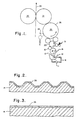
- a press using a keyless inking system will comprise an ink reservoir or sump 10, a pump 11 and piping 12 interconnecting an ink pan 13, within which a metering roller 13′ is located, to supply ink to a frictionally driven ink transfer roller 15.
- a reverse angle scraping or metering blade 16 operates against the metering roller 13′ to remove all of the ink on the metering roller 13′ except that in cells, when present.
- Ink from transfer roller 15 is passed onto a substantially smooth inking drum 20 where it is combined with water supplied from dampener 21.
- Dampening fluid can be supplied by any appropriate means, either to the ink roll 20 as shown or directly to the plate roll 25, as indicated by the phantom lines at 26.
- the scraping blade 16 (or other ink removal means) operating against the metering roll 13′ is present to continuously remove substantially all of the excess ink film therefrom.
- All of the aforesaid elements function to supply a uniform film of ink to the printing plate 28 mounted on press driven plate cylinder 25.
- the plate on cylinder 25 in turn supplies ink in the form of an image, for example, to a paper web 30 being fed through the printing nip formed by the coacting blanket cylinder 31 and impression cylinder 32.
- All of the rollers in Figs. 1 and 2 are configured substantially axially parallel.
- the amount of ink reaching the printing plate may be controlled by the dimensions of depressions or ink receiving cells formed in the surface of the ink metering roller in conjunction with a coextensive scraping or doctor blade that continuously removes virtually all of the ink from the celled metering roller except that carried in the cells or recesses.
- the ink metering roller is composed of a steel or aluminum or comparable core material of suitable strength, length and diameter that is suitably coated with a relatively thick wear-resistant ceramic material. While the roll surface need not be engraved in all instances laser engraving can be used to form accurately dimensioned and positioned cells or recesses, which cells together with a scraping doctor blade serve to precisely meter a required volume of ink. To ensure accurate and continuous metering of ink by all regions of the roller surface for the wear-related useful lifetime of the roller, the ceramic materials are infused with a material that reacts with the ceramic matrix to form a hydrophobic and oleophilic reaction product.
- Fig. 2 is a cross-sectional view of one form of this invention in which the base roller used to produce metering roller 14 is engraved before application of the ceramic coating indicated by numeral 35.
- the celled metering roller 13′ illustrated in the drawings may be, as previously mentioned, mechanically-engraved and then coated or may be first coated and then laser-engraved to form patterned cells of depressions in the coated surface of the roller.
- the volume and frequency of the depressions are selected based on the volume of ink required to meet the printed optical density specifications and in accordance with known practices.
- the roller may have a nominally smooth face with the hard, oleophilic and hydrophobic surface properties added as herein described.
- Roller 13′ is employed typically together with a scraping or doctoring blade 16 to meter the input of ink into the press system.
- Roller 20 may instead be typically employed as the metering roller in a position closer to the printing plate and function together with a scraping blade (not shown) that removes from the printing system virtually all of used return ink that exists at that location.
- Rollers 13′ and 15 are then not needed.
- the return film of ink that is the unused portion of the input ink, is continuously scraped off and led to sump 10 for subsequent continuous recirculation by pump 11 back to the celled metering roller 13′.
- Many of these keyless lithography press operational elements are described in more detail in Fadner, et al U.S. Patent 4,690,055.
- hydrophilic or water-loving surfaces such as ceramic materials are, in the absence of water, oleophilic or oil loving.
- the ink When fresh, unused, water-free lithographic ink is applied to a ceramic, the ink initially exhibits good adhesion to and wetting of the roller surface. Under these initial conditions, normal ink-metering performance is observed.
- a condition is reached where a combination of roller nip pressure and increasing water content in the ink force water through the ink layer to the ceramic metering roller surface. By adhering preferentially to the rollers' surface, the water debonds the ink from that surface, thereby disallowing subsequent pickup of ink from the ink input means.
- a steel or aluminum or other suitable roller may be mechanically engraved in patterns similar for instance to those shown in Fig. 2, then flame-spray ceramic coated to the maximum thickness that substantially retains the cell structure originally present in the core's surface, about 5 to 8 mils.
- the roller can be given a hard anodizing treatment to form the ceramic-like layer in situ.
- the deposition process normally requires repeated thin-application passes of the ceramic coating apparatus, and may be followed by infusion with a selected organic substance, as elsewhere described herein.
- the roller core is similarly mechanically engraved, then one-pass flame-spray coated with a thin film of ceramic powder to a coating thickness typically less than about 0.1 to 0.2 mil, then infused with the material that reacts with the ceramic to form the oleophilic and hydrophobic substance, then given another ceramic coating pass, then another infusion treatment and so on until the desired 5 to 8 mil thick ceramic coating is built-up by successive coating and infusion treatments.
- the desired microporous layer can be obtained also by subjecting a steel or aluminum roller core to a multiple-pass flame-spray coating with the selected ceramic particles to build up a thick, from 3 to about 10 mil or more coating.
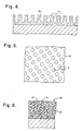
- This coating such as indicated by numeral 40 in Figs. 4 and 5, is then laser engraved to create cell patterns 41 for instance as depicted in Fig. 3, after which the reactive agent is infused into the ceramic surface.
- the same sort of structure can be obtained where the reactive agent is applied after each flame-spray coating pass in a series of about 6 to 20 or so sequences, to achieve the desired oleophilic and hydrophobic ceramic coating thickness, then laser engraved to create the required ink carrying capacity.
- Reactive agents are here meant to mean those organic substances that can be infused into and react with and thereby become chemically attached to the microporous ceramic to form a reaction product that has oleophilic and hydrophobic properties. These are generally dissolvable solids or liquids that can therefore be applied by mist, spray, dip or other well known application methods.
- One primary objective in applying the reactive agent is to render as much as possible of the microporous ceramic powder coating surfaces oleophilic and hydrophobic by penetration of the hydrophobe as deep into the coating as possible.
- Highly mobile liquid systems are preferred.
- Simple spray-painting techniques are appropriate as are dip-coating with roller rotation. Dilute solutions of the reactive agent in solvents that allow seconds to minutes open-time will help to provide penetration deep into the interstices of the ceramic coating.
- the ultimate oleophilic and hydrophobic reaction product must be rendered essentially immobile and firmly adhered to or entrapped within the ceramic powder coating's voids and surfaces.
- the objects of this invention are achieved through the infusion of materials that are chemically reactive with high energy surfaces to form hydrophobic and oleophilic films. Generally, these will be long chain hydrocarbons or substantially hydrocarbon polymeric materials having chemically reactive groups incorporated thereto. Materials which fulfill the requirements are those selected from the group consisting of titanate coupling agents marketed by Kenrich Petrochemicals of Bayonne, N.J. and silane agents marketed by Lord Chemical Co. of Erie, PA.
- Effective titanate coupling agents are: isopropyl, tri (dioctylpyrophosphato) titanate; titaniium di (octylpyrophosphato) oxyacetate; isopropy, triisosteroyl titanate; tetra diallyloxy-methyl 1-1 butoxy titanium di (ditridecyl) phosphite; and di (dioctylphosphato) ethylene titanate.
- Effective silane coupling agents are isobutyltrimethoxysilane and n-octyltriethoxysilane.
- Fig. 6 of the drawings illustrates the manner in which the reactive agent is infused into the interstitial voids formed by the ceramic coating.
- numeral 50 indicates generally the composite wear resistant layer
- numeral 51 identifies the particles of ceramic material
- numeral 52 the infused substance which reacts with particles 51 to form the required oleophilic and hydrophobic reaction product.
- the entire interconnecting network of voids formed by the deposited ceramic layer be infused substantially completely throughout the volume of the layer.
- the important criterion for the resulting roller's use as a lithographic inking roller can be more-or-less predicted by measuring the degree to which droplets of ink oil and of water will spontaneously spread out on the surface of the treated roller.
- the sessile drop technique as described in standard surface chemistry textbooks is suitable for measuring this quality.
- oleophilic and hydrophobic roller materials will have an ink oil (Flint Ink Co.) contact angle of nearly 0° and a distilled water contact angle of about 90° or higher and these values serve to define an oleophilic and hydrophobic material.
- Best Water contact angle 90° or higher Ink Oil contact angle 10° or lower and spreading. Maybe Acceptable Water contact angle 80° or higher. Ink Oil contact angle 10° or lower and spreading. Probably Not Acceptable Water contact angle less than about 80° Ink Oil contact angle greater than 10° and/or non-spreading.
Landscapes
- Inking, Control Or Cleaning Of Printing Machines (AREA)
- Printing Plates And Materials Therefor (AREA)
- Impression-Transfer Materials And Handling Thereof (AREA)
- Laminated Bodies (AREA)
Applications Claiming Priority (2)
| Application Number | Priority Date | Filing Date | Title |
|---|---|---|---|
| US343556 | 1989-04-27 | ||
| US07/343,556 US4977830A (en) | 1989-04-27 | 1989-04-27 | Hydrophobic and oleophilic microporous inking rollers |
Publications (3)
| Publication Number | Publication Date |
|---|---|
| EP0394561A2 true EP0394561A2 (fr) | 1990-10-31 |
| EP0394561A3 EP0394561A3 (fr) | 1991-01-30 |
| EP0394561B1 EP0394561B1 (fr) | 1995-04-12 |
Family
ID=23346598
Family Applications (1)
| Application Number | Title | Priority Date | Filing Date |
|---|---|---|---|
| EP89124065A Expired - Lifetime EP0394561B1 (fr) | 1989-04-27 | 1989-12-28 | Rouleaux encreurs oléphiles hydrophobes et microporeux |
Country Status (6)
| Country | Link |
|---|---|
| US (1) | US4977830A (fr) |
| EP (1) | EP0394561B1 (fr) |
| JP (1) | JPH07427B2 (fr) |
| AU (1) | AU633535B2 (fr) |
| CA (1) | CA2005577C (fr) |
| DE (2) | DE394561T1 (fr) |
Cited By (1)
| Publication number | Priority date | Publication date | Assignee | Title |
|---|---|---|---|---|
| DE4442235A1 (de) * | 1993-12-01 | 1995-06-08 | Roland Man Druckmasch | Formzylinder und Walzen in einer Druckmaschine |
Families Citing this family (7)
| Publication number | Priority date | Publication date | Assignee | Title |
|---|---|---|---|---|
| FI83439C (fi) * | 1989-08-24 | 1991-07-10 | Valmet Paper Machinery Inc | Vals i pappersmaskin och foerfarande foer framstaellning av denna. |
| US5111568A (en) * | 1989-08-24 | 1992-05-12 | Valmet Paper Machinery Inc. | Paper machine roll |
| US5257966A (en) * | 1990-10-08 | 1993-11-02 | Yamauchi Corporation | Press roll for paper machines |
| US5207158A (en) * | 1991-02-19 | 1993-05-04 | Rockwell International | Long lived, variable-delivery ink metering method, system and roller for keyless lithography |
| DE4210529A1 (de) * | 1991-12-11 | 1993-10-07 | Kochsmeier Hans Hermann | Dosiervorrichtung für flüssige Auftragsmittel |
| DE10104164B4 (de) * | 2001-01-30 | 2005-11-10 | Nanogate Coating Systems Gmbh | Gegenstand mit Versiegelung und dessen Verwendung in einer Druckmaschine |
| US6673391B1 (en) * | 2002-08-09 | 2004-01-06 | Alcoa Inc. | Ceramic applicator device and method of use |
Family Cites Families (9)
| Publication number | Priority date | Publication date | Assignee | Title |
|---|---|---|---|---|
| US3163534A (en) * | 1961-03-13 | 1964-12-29 | Harris Intertype Corp | Lithographic plate including a hydrophilic barrier layer comprising a silane, an acrylic compound, and an organic metal ester |
| US3694251A (en) * | 1964-02-27 | 1972-09-26 | Eastman Kodak Co | Coated article having a layer of boehmite and alkyl titanate |
| DE1299661B (de) * | 1964-02-27 | 1969-07-24 | Eastman Kodak Co | Verfahren zur Verbesserung der hydrophilen Eigenschaften der Traeger von fuer Flachdruckverfahren geeigneten Druckplatten |
| US4301730A (en) * | 1977-09-29 | 1981-11-24 | Pamarco Incorporated | Anilox roll and method of making the same |
| US4179537A (en) * | 1978-01-04 | 1979-12-18 | Rykowski John J | Silane coupling agents |
| GB2049102A (en) * | 1979-05-03 | 1980-12-17 | Csi Corp | Transfer roll |
| JPS5856855A (ja) * | 1981-09-30 | 1983-04-04 | Tokyo Kikai Seisakusho:Kk | オフセツト印刷用メツシユロ−ル |
| DE3316348C2 (de) * | 1983-05-05 | 1985-03-07 | PTG Plasma-Oberflächentechnik GmbH, 7240 Horb | Verfahren zum Beschichten eines Werkstückes |
| JPS6044394A (ja) * | 1983-08-22 | 1985-03-09 | Mitsubishi Heavy Ind Ltd | インキロ−ラ |
-
1989
- 1989-04-27 US US07/343,556 patent/US4977830A/en not_active Expired - Lifetime
- 1989-12-14 CA CA002005577A patent/CA2005577C/fr not_active Expired - Fee Related
- 1989-12-28 EP EP89124065A patent/EP0394561B1/fr not_active Expired - Lifetime
- 1989-12-28 DE DE198989124065T patent/DE394561T1/de active Pending
- 1989-12-28 DE DE68922211T patent/DE68922211T2/de not_active Expired - Fee Related
-
1990
- 1990-01-09 AU AU47834/90A patent/AU633535B2/en not_active Ceased
- 1990-03-06 JP JP2054792A patent/JPH07427B2/ja not_active Expired - Fee Related
Cited By (2)
| Publication number | Priority date | Publication date | Assignee | Title |
|---|---|---|---|---|
| DE4442235A1 (de) * | 1993-12-01 | 1995-06-08 | Roland Man Druckmasch | Formzylinder und Walzen in einer Druckmaschine |
| DE4442235C2 (de) * | 1993-12-01 | 2002-12-05 | Roland Man Druckmasch | Verfahren zur Herstellung einer Druckform für einen Formzylinder einer Druckmaschine und danach hergestellte Druckform |
Also Published As
| Publication number | Publication date |
|---|---|
| EP0394561A3 (fr) | 1991-01-30 |
| JPH07427B2 (ja) | 1995-01-11 |
| DE394561T1 (de) | 1991-02-28 |
| AU4783490A (en) | 1990-11-01 |
| EP0394561B1 (fr) | 1995-04-12 |
| CA2005577A1 (fr) | 1990-10-27 |
| JPH02299890A (ja) | 1990-12-12 |
| DE68922211T2 (de) | 1995-11-02 |
| US4977830A (en) | 1990-12-18 |
| CA2005577C (fr) | 1993-10-19 |
| DE68922211D1 (de) | 1995-05-18 |
| AU633535B2 (en) | 1993-02-04 |
Similar Documents
| Publication | Publication Date | Title |
|---|---|---|
| US4601242A (en) | Copper and ceramic composite ink metering roller | |
| CA1240206A (fr) | Rouleau a strates de cuivre et de nickel doseur d'encrage | |
| CA1224081A (fr) | Rouleau d'encrage de presse lithographique | |
| US4862799A (en) | Copper coated anodized aluminum ink metering roller | |
| US4991501A (en) | Dampening water feed roller for planographic printing press | |
| US5127325A (en) | Hydrophobic and oleophilic microporous inking rollers | |
| US4977830A (en) | Hydrophobic and oleophilic microporous inking rollers | |
| EP0499848A1 (fr) | Système durable pour le transfert variable et déterminé d'encre d'imprimerie ainsi qu'un rouleau pour l'impression sans clés d'encrage | |
| US5370052A (en) | Method of controlling the quantity of printing ink and reconditioning used anilox rollers | |
| JPH0286496A (ja) | インキローラの製作方法とこの方法を実施するための装置 | |
| CA2006227C (fr) | Rouleaux encreurs a micropores, hydrophobes et oleophiles | |
| US4603634A (en) | Copper and nickel layered ink metering roller | |
| EP0394560B1 (fr) | Rouleaux encreurs oléophiles hydrophobes et microporeux | |
| JPH0342596B2 (fr) | ||
| EP0316515B1 (fr) | Rouleau encreur en aluminium anodisé recouvert de cuivre | |
| US20040226461A1 (en) | Roll for a printing press and process for manufacturing a roll | |
| DE102005062204A1 (de) | Verschleißschutzbeschichtung | |
| JPS6311341A (ja) | 平版印刷用メツシユロ−ル | |
| JP2008253882A (ja) | ローラの製造方法 |
Legal Events
| Date | Code | Title | Description |
|---|---|---|---|
| PUAI | Public reference made under article 153(3) epc to a published international application that has entered the european phase |
Free format text: ORIGINAL CODE: 0009012 |
|
| AK | Designated contracting states |
Kind code of ref document: A2 Designated state(s): CH DE FR GB LI SE |
|
| PUAL | Search report despatched |
Free format text: ORIGINAL CODE: 0009013 |
|
| EL | Fr: translation of claims filed | ||
| AK | Designated contracting states |
Kind code of ref document: A3 Designated state(s): CH DE FR GB LI SE |
|
| DET | De: translation of patent claims | ||
| 17P | Request for examination filed |
Effective date: 19910605 |
|
| 17Q | First examination report despatched |
Effective date: 19930623 |
|
| GRAA | (expected) grant |
Free format text: ORIGINAL CODE: 0009210 |
|
| AK | Designated contracting states |
Kind code of ref document: B1 Designated state(s): CH DE FR GB LI SE |
|
| REF | Corresponds to: |
Ref document number: 68922211 Country of ref document: DE Date of ref document: 19950518 |
|
| ET | Fr: translation filed | ||
| PLBE | No opposition filed within time limit |
Free format text: ORIGINAL CODE: 0009261 |
|
| STAA | Information on the status of an ep patent application or granted ep patent |
Free format text: STATUS: NO OPPOSITION FILED WITHIN TIME LIMIT |
|
| 26N | No opposition filed | ||
| REG | Reference to a national code |
Ref country code: CH Ref legal event code: PUE Owner name: ROCKWELL INTERNATIONAL CORPORATION TRANSFER- GOSS |
|
| REG | Reference to a national code |
Ref country code: FR Ref legal event code: TP |
|
| REG | Reference to a national code |
Ref country code: GB Ref legal event code: 732E |
|
| REG | Reference to a national code |
Ref country code: GB Ref legal event code: IF02 |
|
| PGFP | Annual fee paid to national office [announced via postgrant information from national office to epo] |
Ref country code: FR Payment date: 20051216 Year of fee payment: 17 |
|
| PGFP | Annual fee paid to national office [announced via postgrant information from national office to epo] |
Ref country code: GB Payment date: 20051221 Year of fee payment: 17 |
|
| PGFP | Annual fee paid to national office [announced via postgrant information from national office to epo] |
Ref country code: CH Payment date: 20051227 Year of fee payment: 17 Ref country code: SE Payment date: 20051227 Year of fee payment: 17 |
|
| PGFP | Annual fee paid to national office [announced via postgrant information from national office to epo] |
Ref country code: DE Payment date: 20060131 Year of fee payment: 17 |
|
| PG25 | Lapsed in a contracting state [announced via postgrant information from national office to epo] |
Ref country code: SE Free format text: LAPSE BECAUSE OF NON-PAYMENT OF DUE FEES Effective date: 20061229 |
|
| PG25 | Lapsed in a contracting state [announced via postgrant information from national office to epo] |
Ref country code: CH Free format text: LAPSE BECAUSE OF NON-PAYMENT OF DUE FEES Effective date: 20061231 Ref country code: LI Free format text: LAPSE BECAUSE OF NON-PAYMENT OF DUE FEES Effective date: 20061231 |
|
| PG25 | Lapsed in a contracting state [announced via postgrant information from national office to epo] |
Ref country code: DE Free format text: LAPSE BECAUSE OF NON-PAYMENT OF DUE FEES Effective date: 20070703 |
|
| REG | Reference to a national code |
Ref country code: CH Ref legal event code: PL |
|
| EUG | Se: european patent has lapsed | ||
| GBPC | Gb: european patent ceased through non-payment of renewal fee |
Effective date: 20061228 |
|
| REG | Reference to a national code |
Ref country code: FR Ref legal event code: ST Effective date: 20070831 |
|
| PG25 | Lapsed in a contracting state [announced via postgrant information from national office to epo] |
Ref country code: GB Free format text: LAPSE BECAUSE OF NON-PAYMENT OF DUE FEES Effective date: 20061228 |
|
| PG25 | Lapsed in a contracting state [announced via postgrant information from national office to epo] |
Ref country code: FR Free format text: LAPSE BECAUSE OF NON-PAYMENT OF DUE FEES Effective date: 20070102 |