EP0394978A2 - Cadre de construction pour four à micro-ondes et pareil - Google Patents
Cadre de construction pour four à micro-ondes et pareil Download PDFInfo
- Publication number
- EP0394978A2 EP0394978A2 EP90107800A EP90107800A EP0394978A2 EP 0394978 A2 EP0394978 A2 EP 0394978A2 EP 90107800 A EP90107800 A EP 90107800A EP 90107800 A EP90107800 A EP 90107800A EP 0394978 A2 EP0394978 A2 EP 0394978A2
- Authority
- EP
- European Patent Office
- Prior art keywords
- front panel
- frame construction
- joining
- rear plate
- jigs
- Prior art date
- Legal status (The legal status is an assumption and is not a legal conclusion. Google has not performed a legal analysis and makes no representation as to the accuracy of the status listed.)
- Granted
Links
Images


Classifications
-
- H—ELECTRICITY
- H05—ELECTRIC TECHNIQUES NOT OTHERWISE PROVIDED FOR
- H05B—ELECTRIC HEATING; ELECTRIC LIGHT SOURCES NOT OTHERWISE PROVIDED FOR; CIRCUIT ARRANGEMENTS FOR ELECTRIC LIGHT SOURCES, IN GENERAL
- H05B6/00—Heating by electric, magnetic or electromagnetic fields
- H05B6/64—Heating using microwaves
- H05B6/6426—Aspects relating to the exterior of the microwave heating apparatus, e.g. metal casing, power cord
-
- F—MECHANICAL ENGINEERING; LIGHTING; HEATING; WEAPONS; BLASTING
- F24—HEATING; RANGES; VENTILATING
- F24C—DOMESTIC STOVES OR RANGES ; DETAILS OF DOMESTIC STOVES OR RANGES, OF GENERAL APPLICATION
- F24C15/00—Details
- F24C15/08—Foundations or supports plates; Legs or pillars; Casings; Wheels
-
- Y—GENERAL TAGGING OF NEW TECHNOLOGICAL DEVELOPMENTS; GENERAL TAGGING OF CROSS-SECTIONAL TECHNOLOGIES SPANNING OVER SEVERAL SECTIONS OF THE IPC; TECHNICAL SUBJECTS COVERED BY FORMER USPC CROSS-REFERENCE ART COLLECTIONS [XRACs] AND DIGESTS
- Y10—TECHNICAL SUBJECTS COVERED BY FORMER USPC
- Y10T—TECHNICAL SUBJECTS COVERED BY FORMER US CLASSIFICATION
- Y10T29/00—Metal working
- Y10T29/49—Method of mechanical manufacture
- Y10T29/49826—Assembling or joining
- Y10T29/49892—Joining plate edge perpendicularly to frame
Definitions
- the present invention generally relates to a heating apparatus and more particularly, to a frame or cabinet construction for a microwave oven having a heating chamber, so-called oven toaster or the like.
- Fig. 5 shows a conventional frame construction 1 for a microwave oven, which mainly includes a front panel 2 having a generally rectangular shape, a rear plate 3 disposed at the back thereof, a bottom plate 4 fixed to lower edges of the respective front panel 2 and rear plate 3, a top plate 5 secured to upper portions of said front panel 2 and rear plate 3 in a parallel relation with said bottom plate 4, and an oven structure 6 having a generally U-shaped cross section and fixed at its front and rear edges, to the front panel 2 and rear plate 3 and at its upper edges, to the top plate 5 respectively.
- Each of the plate members referred to above has folded portions as welding margins, at respective edge portions thereof to be connected.
- the plate members 2,3,5 and 6 other than the above bottom plate 4 are preliminarily combined to each other through fixing by welding and the like, thereby forming an oven (i.e. a heating chamber) surrounded by the respective members. Thereafter, the plate members thus combined are subjected to a painting finish for subsequent drying. Then, the bottom plate 4 is fixed to the lower edges of said front panel 2 and the rear plate 3 by set screws 7, whereby the frame construction 1 for the microwave oven is completed.
- the known frame construciton 1 is mainly constituted by the five plate members 2,3,4,5, and 6 as described above, press work, for example, in twenty-seven steps has been required for the manufacture of said plate members, and moreover, further processings have also been involved for welding such plate members to each other, and also for fixing the bottom plate 4 by the set screws 7 which must be supplied as separate parts.
- an essential object of the present invention is to provide an improved frame construction for a microwave oven and the like, which requires less man-hour for the manufacture, and smaller number of parts involved, and may be readily subjected to physical distribution.
- Another object of the present invention is to provide a frame construction of the above described type, which is simple in structure and stable in functioning at high reliability.
- a frame construction for a microwave oven and the like which includes a fornt panel having a generally rectangular configuration at its front face, a rear plate having approximately the same configuration as that of said front panel and disposed at the back thereof, a bottom plate also having generally a rectangular shape and fixed to lower edges of said front panel and said rear plate for connection therebetween, a top plate fixed to upper portions of the respective front panel and rear plate in a parallel relation with said bottom plate, and an oven structure of a generally U-shaped cross section fixed, at its front and rear edges, to said front panel and said rear plate for connection and, at its upper edges, to said top plate to constitute a heating chamber.
- the front panel, bottom plate and rear plate are integrally formed to constitute an open chassis threby, while the bottom plate is formed with an inserting opening for inserting oven structure joining jigs threthrough.
- the frame construction for a microwave oven, etc. as described above, since the front panel portion, bottom plate portion and rear plate portion of the frame construction constituted by the front panel, rear plate, bottom plate, top plate and oven structure, are integrally formed as one unit, it becomes possible to reduce the man-hour in the press work steps, with simultaneous reduction in the number of the involved parts including the set secrews etc. required for the assembly. Furtheremore, since the inserting opening for inserting the oven structure joining jigs therethrough is formed in said bottom plate, such jigs may be guided to the joining portions between the oven structure and the front panel, and also, the rear plate for efficient joining of the oven structure, front panel, and rear plate.
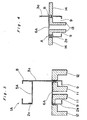
- Figs. 1 and 2 a frame construction IA for a microwave oven according to one preferred embodiment of the present invention, in which like parts in the conventional arrangement described earlier with reference to Fig. 5 are designated by like reference numerals for brevity of description.
- the frame construction 1A of the present invention differs from the conventional frame construction 1 of Fig. 5 mainly in that a front panel portion 2a, a bottom plate portion 4a, and a rear plate portion 3a, which are equivalent to the front panel 2, bottom plate 4 and rear plate 3 in Fig. 5, are integrally formed into one unit as an open chassis 8, and also, in that an inserting opening 9 is formed in the bottom plate portion 4a of the open chassis 8 in position below the oven structure 6A so that welding jigs 11 (Fig. 3) may be guided into the frame construction 1A therethrough for joining folded portions lu formed at the front and rear lower edges of the oven structure 6A, with corresponding portions of the front panel portion 2a and the rear plate portion 3a.
- the oven i.e. the heating chamber for the microwave oven is surrounded by the front panel portion 2a, rear plate portion 3a, oven structure 6A and top plate 5A, with a square opening O is defined in the front panel portion 2a for permitting a food article to be inserted into or withdrawn front the heating chamber therethrough. More specifically, respective front edge portions of the oven structure 6A and top plate 5A are joined with the front panel portion 2a along the corresponding edge portions of said square opening O.
- two sides at the upper edges of the oven structure 6A are first joined to the top plate 5A by welding. Then, six sides at the front and rear side edges of the top plate 5A and oven structure 6A are respectively joined to the front panel portion 2a and the rear plate portion 3a. More specifically, at the front edge portions as referred to above, the three sides indicated by dotted lines q in Fig. 1 are joined, and at the rear edge portions, corresponding three sides (not shown) located at the same positions as said three sides at the fornt edge portions in a horizontal direction are joined in the similar manner. Subsequently, two sides at the fornt and rear lower edges of the oven structure 6A are joined (In Fig. 1, only one side at the front lower edge of the oven structure 6A is shown by a dotted line r).
- the welding jigs 11 may be inserted through said opening 9 as shown in Fig. 3 so as to be led to the front and rear lower edge portions of the oven structure 6A to be joined.
- the welding jigs 11, in cooperation with mating welding jigs 12, subject the oven structure 6A and the front panel portion 2a and the rear plate portion 3a of the open chassis 8 to welding for the joining therebetween. Subsequently, painting is applied to complete the frame structure 1A for the microwave oven.
- welding jigs 11 and 12 are employed as the joining means, this may be replaced by caulking means 13 and 14 for mechanical joining through modification of the joining portions between the oven structure 6A and the front panel portion 2a and the rear plate portion 3a, respectively to a lock seaming portion A or riveted portion B as shown in Fig. 4.
- the frame construction for a microwave oven and the like which includes the front panel having a generally rectangular configuration at its front face, the rear plate having approximately the same configuration as that of said front panel and disposed at the back thereof, the bottom plate also having generally a rectangular shape and fixed to lower edges of said front panel and said rear plate for connection therebetween, the top plate fixed to upper portions of the respective front panel and rear plate in a parallel relation with said bottom plate, and the oven structure of a generally U-shaped cross section fixed, at its front and rear edges, to said front panel and said rear plate for connection and, at its upper edges, to said top plate to constitute a heating chamber, said front panel, said bottom plate and said rear plate are integrally formed to constitute the open chassis thereby, while said bottom plate is formed with an inserting opening for inserting oven structure joining jigs therethrough, and therefore, not only the number of parts and man-hour required for the
Landscapes
- Engineering & Computer Science (AREA)
- Chemical & Material Sciences (AREA)
- Combustion & Propulsion (AREA)
- Mechanical Engineering (AREA)
- General Engineering & Computer Science (AREA)
- Physics & Mathematics (AREA)
- Electromagnetism (AREA)
- Electric Ovens (AREA)
- Electric Stoves And Ranges (AREA)
- Baking, Grill, Roasting (AREA)
Applications Claiming Priority (2)
| Application Number | Priority Date | Filing Date | Title |
|---|---|---|---|
| JP1989049081U JPH074405Y2 (ja) | 1989-04-25 | 1989-04-25 | 加熱調理器の枠体構造 |
| JP49081/89U | 1989-04-25 |
Publications (3)
| Publication Number | Publication Date |
|---|---|
| EP0394978A2 true EP0394978A2 (fr) | 1990-10-31 |
| EP0394978A3 EP0394978A3 (fr) | 1991-04-10 |
| EP0394978B1 EP0394978B1 (fr) | 1993-02-17 |
Family
ID=12821146
Family Applications (1)
| Application Number | Title | Priority Date | Filing Date |
|---|---|---|---|
| EP90107800A Expired - Lifetime EP0394978B1 (fr) | 1989-04-25 | 1990-04-25 | Cadre de construction pour four à micro-ondes et pareil |
Country Status (8)
| Country | Link |
|---|---|
| US (1) | US5017750A (fr) |
| EP (1) | EP0394978B1 (fr) |
| JP (1) | JPH074405Y2 (fr) |
| KR (1) | KR930004207B1 (fr) |
| CN (1) | CN1047432A (fr) |
| AU (1) | AU609007B2 (fr) |
| CA (1) | CA2015258C (fr) |
| DE (1) | DE69000923T2 (fr) |
Cited By (8)
| Publication number | Priority date | Publication date | Assignee | Title |
|---|---|---|---|---|
| EP0606513A1 (fr) * | 1993-01-15 | 1994-07-20 | INOXVENETA S.p.A. | Procédé pour fabriquer une enceinte, en particulier pour traitement de produits alimentaires et enceinte obtenue par ce procédé |
| ES2064252A2 (es) * | 1992-01-17 | 1995-01-16 | Moulinex Sa | Procedimiento de conformacion de una chapa en al menos un diedro con caras interiores esmaltadas y recinto de horno correspondiente. |
| GB2298113A (en) * | 1995-02-17 | 1996-08-21 | Samsung Electronics Co Ltd | Microwave ovens |
| EP0743491A1 (fr) * | 1995-05-16 | 1996-11-20 | Lg Electronics Inc. | Structure du corps principal d'un four à micro-ondes |
| EP0803683A1 (fr) * | 1996-04-23 | 1997-10-29 | Samsung Electronics Co., Ltd. | Boîtier notamment pour un four à micro-onde |
| DE102007008772A1 (de) * | 2006-11-30 | 2008-06-05 | BSH Bosch und Siemens Hausgeräte GmbH | Hausgerätewandungsanordnung und Verfahren zur Befestigung von Wandungsteilen bei einem Hausgerät |
| EP1978310A1 (fr) * | 2007-04-02 | 2008-10-08 | Whirlpool Corporation | Structure de four modulaire |
| EP1758435A3 (fr) * | 2000-12-28 | 2011-05-11 | LG Electronics Inc. | Chambre pour composants électriques dans un four à micro-ondes |
Families Citing this family (3)
| Publication number | Priority date | Publication date | Assignee | Title |
|---|---|---|---|---|
| US5286940A (en) * | 1992-08-28 | 1994-02-15 | Leeds Harlan S | Microwave oven break away element trim kit |
| US6894260B2 (en) * | 2001-12-04 | 2005-05-17 | Matsushita Electric Industrial Co., Ltd. | High frequency heating apparatus |
| DE102004047997A1 (de) * | 2004-10-01 | 2006-04-06 | BSH Bosch und Siemens Hausgeräte GmbH | Ofen zur Garbehandlung von Lebensmitteln |
Family Cites Families (12)
| Publication number | Priority date | Publication date | Assignee | Title |
|---|---|---|---|---|
| US2813185A (en) * | 1954-03-08 | 1957-11-12 | Raytheon Mfg Co | Heating devices |
| US3300615A (en) * | 1963-07-09 | 1967-01-24 | Lyons & Co Ltd J | Electronic ovens |
| CA1086831A (fr) * | 1975-11-07 | 1980-09-30 | Kurt H. Carlsson | Four a micro-ondes comprenant une ligne de transmission sous forme de bande conductrice |
| US4163141A (en) * | 1976-04-14 | 1979-07-31 | Matsushita Electric Industrial Co., Ltd. | Microwave oven |
| US4282416A (en) * | 1978-08-21 | 1981-08-04 | General Electric Co. | Unitized structure for a microwave oven |
| CA1184458A (fr) * | 1981-06-16 | 1985-03-26 | Noboru Igarashi | Chambre d'appareil de cuisson |
| US4563560A (en) * | 1982-06-11 | 1986-01-07 | Litton Systems, Inc. | Microwave oven construction |
| IE54739B1 (en) * | 1982-11-29 | 1990-01-17 | Litton Systems Inc | Microwave oven with common wrap and cavity walls |
| US4563559A (en) * | 1982-12-27 | 1986-01-07 | Enami Seiki Mfg. Co., Ltd. | Inner box for a cooking appliance |
| JPS616107U (ja) * | 1984-06-15 | 1986-01-14 | シャープ株式会社 | 電子レンジのオ−ブンの構造 |
| US4609801A (en) * | 1985-07-08 | 1986-09-02 | Whirlpool Corporation | Cavity construction for microwave oven |
| US4680439A (en) * | 1986-05-30 | 1987-07-14 | Litton Systems, Inc. | Plastic microwave oven cavity |
-
1989
- 1989-04-25 JP JP1989049081U patent/JPH074405Y2/ja not_active Expired - Fee Related
-
1990
- 1990-04-24 US US07/513,770 patent/US5017750A/en not_active Expired - Lifetime
- 1990-04-24 AU AU53843/90A patent/AU609007B2/en not_active Expired
- 1990-04-24 CA CA002015258A patent/CA2015258C/fr not_active Expired - Lifetime
- 1990-04-25 CN CN90104132A patent/CN1047432A/zh active Pending
- 1990-04-25 KR KR1019900005825A patent/KR930004207B1/ko not_active Expired - Lifetime
- 1990-04-25 EP EP90107800A patent/EP0394978B1/fr not_active Expired - Lifetime
- 1990-04-25 DE DE9090107800T patent/DE69000923T2/de not_active Expired - Lifetime
Cited By (10)
| Publication number | Priority date | Publication date | Assignee | Title |
|---|---|---|---|---|
| ES2064252A2 (es) * | 1992-01-17 | 1995-01-16 | Moulinex Sa | Procedimiento de conformacion de una chapa en al menos un diedro con caras interiores esmaltadas y recinto de horno correspondiente. |
| EP0606513A1 (fr) * | 1993-01-15 | 1994-07-20 | INOXVENETA S.p.A. | Procédé pour fabriquer une enceinte, en particulier pour traitement de produits alimentaires et enceinte obtenue par ce procédé |
| GB2298113A (en) * | 1995-02-17 | 1996-08-21 | Samsung Electronics Co Ltd | Microwave ovens |
| EP0743491A1 (fr) * | 1995-05-16 | 1996-11-20 | Lg Electronics Inc. | Structure du corps principal d'un four à micro-ondes |
| US5818017A (en) * | 1995-05-16 | 1998-10-06 | Lg Electronics Inc. | Microwave oven main body structure |
| EP0803683A1 (fr) * | 1996-04-23 | 1997-10-29 | Samsung Electronics Co., Ltd. | Boîtier notamment pour un four à micro-onde |
| US5938967A (en) * | 1996-04-23 | 1999-08-17 | Samsung Electronics Co., Ltd. | Casing structure of a microwave oven |
| EP1758435A3 (fr) * | 2000-12-28 | 2011-05-11 | LG Electronics Inc. | Chambre pour composants électriques dans un four à micro-ondes |
| DE102007008772A1 (de) * | 2006-11-30 | 2008-06-05 | BSH Bosch und Siemens Hausgeräte GmbH | Hausgerätewandungsanordnung und Verfahren zur Befestigung von Wandungsteilen bei einem Hausgerät |
| EP1978310A1 (fr) * | 2007-04-02 | 2008-10-08 | Whirlpool Corporation | Structure de four modulaire |
Also Published As
| Publication number | Publication date |
|---|---|
| AU5384390A (en) | 1990-11-08 |
| JPH02140204U (fr) | 1990-11-22 |
| DE69000923D1 (de) | 1993-03-25 |
| DE69000923T2 (de) | 1993-06-03 |
| AU609007B2 (en) | 1991-04-18 |
| EP0394978A3 (fr) | 1991-04-10 |
| CA2015258C (fr) | 1993-10-05 |
| KR900016692A (ko) | 1990-11-14 |
| US5017750A (en) | 1991-05-21 |
| EP0394978B1 (fr) | 1993-02-17 |
| JPH074405Y2 (ja) | 1995-02-01 |
| KR930004207B1 (ko) | 1993-05-21 |
| CA2015258A1 (fr) | 1990-10-25 |
| CN1047432A (zh) | 1990-12-05 |
Similar Documents
| Publication | Publication Date | Title |
|---|---|---|
| EP0394978A2 (fr) | Cadre de construction pour four à micro-ondes et pareil | |
| US4788395A (en) | Configuration for joining components of a microwave oven | |
| US5475919A (en) | PCMCIA card manufacturing process | |
| US5735411A (en) | Constructional system | |
| CA1256510A (fr) | Configuration de cavite pour four a micro-ondes | |
| GB2243770A (en) | Top for domestic appliance | |
| US6231384B1 (en) | Panel mounted cable end connector | |
| EP1579152B1 (fr) | Four à micro-ondes | |
| JP2957574B1 (ja) | パチンコ機 | |
| EP4426066A1 (fr) | Appareil de cuisson | |
| EP1050260B1 (fr) | Structure de boítier d'un appareil de chauffage et procédé de fabrication de l'appareil de chauffage contenant une telle structure | |
| US7586069B2 (en) | Inner box for cooker and method of integrating the same | |
| CN215260096U (zh) | 一种空调器中框组件和空调器 | |
| EP0251782A1 (fr) | Assemblages pour enveloppes d'appareils ménagers et de telles enveloppes | |
| US6291765B1 (en) | Electromagnetically shielded housing having metal parts snap-connected via a spring contact strip | |
| CN210112457U (zh) | 一种通用型钣金机箱 | |
| JP2762570B2 (ja) | グリル枠固定装置 | |
| CN217281037U (zh) | 一种电池箱前面板与箱体的安装结构 | |
| CN220874050U (zh) | 电气柜及电气柜组 | |
| EP1626471B1 (fr) | Procédé de fabrication d'une armoire électrique et armoire produit par ce procédé | |
| CN219320730U (zh) | 一种服务器机箱的铆合结构 | |
| JPH0528790Y2 (fr) | ||
| JP3179991B2 (ja) | 電子レンジの構成部品組み立て方法 | |
| JPH04213898A (ja) | 高周波機器用枠体の製造方法 | |
| CN1243199C (zh) | 高频加热装置的空腔构造 |
Legal Events
| Date | Code | Title | Description |
|---|---|---|---|
| PUAI | Public reference made under article 153(3) epc to a published international application that has entered the european phase |
Free format text: ORIGINAL CODE: 0009012 |
|
| AK | Designated contracting states |
Kind code of ref document: A2 Designated state(s): DE FR GB |
|
| 17P | Request for examination filed |
Effective date: 19901215 |
|
| PUAL | Search report despatched |
Free format text: ORIGINAL CODE: 0009013 |
|
| AK | Designated contracting states |
Kind code of ref document: A3 Designated state(s): DE FR GB |
|
| 17Q | First examination report despatched |
Effective date: 19920422 |
|
| GRAA | (expected) grant |
Free format text: ORIGINAL CODE: 0009210 |
|
| AK | Designated contracting states |
Kind code of ref document: B1 Designated state(s): DE FR GB |
|
| REF | Corresponds to: |
Ref document number: 69000923 Country of ref document: DE Date of ref document: 19930325 |
|
| ET | Fr: translation filed | ||
| PLBE | No opposition filed within time limit |
Free format text: ORIGINAL CODE: 0009261 |
|
| STAA | Information on the status of an ep patent application or granted ep patent |
Free format text: STATUS: NO OPPOSITION FILED WITHIN TIME LIMIT |
|
| 26N | No opposition filed | ||
| REG | Reference to a national code |
Ref country code: GB Ref legal event code: IF02 |
|
| PGFP | Annual fee paid to national office [announced via postgrant information from national office to epo] |
Ref country code: FR Payment date: 20090417 Year of fee payment: 20 Ref country code: DE Payment date: 20090428 Year of fee payment: 20 |
|
| PGFP | Annual fee paid to national office [announced via postgrant information from national office to epo] |
Ref country code: GB Payment date: 20090422 Year of fee payment: 20 |
|
| REG | Reference to a national code |
Ref country code: GB Ref legal event code: PE20 Expiry date: 20100424 |
|
| PG25 | Lapsed in a contracting state [announced via postgrant information from national office to epo] |
Ref country code: GB Free format text: LAPSE BECAUSE OF EXPIRATION OF PROTECTION Effective date: 20100424 |
|
| PG25 | Lapsed in a contracting state [announced via postgrant information from national office to epo] |
Ref country code: DE Free format text: LAPSE BECAUSE OF EXPIRATION OF PROTECTION Effective date: 20100425 |