EP0743491A1 - Structure du corps principal d'un four à micro-ondes - Google Patents
Structure du corps principal d'un four à micro-ondes Download PDFInfo
- Publication number
- EP0743491A1 EP0743491A1 EP96100104A EP96100104A EP0743491A1 EP 0743491 A1 EP0743491 A1 EP 0743491A1 EP 96100104 A EP96100104 A EP 96100104A EP 96100104 A EP96100104 A EP 96100104A EP 0743491 A1 EP0743491 A1 EP 0743491A1
- Authority
- EP
- European Patent Office
- Prior art keywords
- wall
- outer plate
- plate
- inner plate
- microwave oven
- Prior art date
- Legal status (The legal status is an assumption and is not a legal conclusion. Google has not performed a legal analysis and makes no representation as to the accuracy of the status listed.)
- Ceased
Links
- 238000000034 method Methods 0.000 claims description 15
- 238000005452 bending Methods 0.000 claims 1
- 238000004049 embossing Methods 0.000 description 10
- 238000003466 welding Methods 0.000 description 7
- 230000003014 reinforcing effect Effects 0.000 description 4
- 238000007792 addition Methods 0.000 description 1
- 230000015572 biosynthetic process Effects 0.000 description 1
- 238000010276 construction Methods 0.000 description 1
- 230000003247 decreasing effect Effects 0.000 description 1
- 238000012986 modification Methods 0.000 description 1
- 230000004048 modification Effects 0.000 description 1
- 235000020825 overweight Nutrition 0.000 description 1
- 238000006467 substitution reaction Methods 0.000 description 1
Images




Classifications
-
- H—ELECTRICITY
- H05—ELECTRIC TECHNIQUES NOT OTHERWISE PROVIDED FOR
- H05B—ELECTRIC HEATING; ELECTRIC LIGHT SOURCES NOT OTHERWISE PROVIDED FOR; CIRCUIT ARRANGEMENTS FOR ELECTRIC LIGHT SOURCES, IN GENERAL
- H05B6/00—Heating by electric, magnetic or electromagnetic fields
- H05B6/64—Heating using microwaves
- H05B6/6426—Aspects relating to the exterior of the microwave heating apparatus, e.g. metal casing, power cord
-
- F—MECHANICAL ENGINEERING; LIGHTING; HEATING; WEAPONS; BLASTING
- F24—HEATING; RANGES; VENTILATING
- F24C—DOMESTIC STOVES OR RANGES ; DETAILS OF DOMESTIC STOVES OR RANGES, OF GENERAL APPLICATION
- F24C15/00—Details
- F24C15/08—Foundations or supports plates; Legs or pillars; Casings; Wheels
Definitions
- the present invention relates to a microwave oven main body structure, and in particular to an improved microwave oven main body structure capable of more easily assembling an outer plate and an inner plate of the main body by forming a support member at the outer plate, so that the support member is engaged with the outer plate of the main body.
- a cavity of a microwave oven consists of two pieces of an outer plate and an inner plate so as to increase productivity of the microwave oven in the industry.
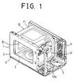
- Fig. 1 shows a conventional microwave oven main body structure, which includes an outer plate which includes a front wall 3 and a rear wall 4.
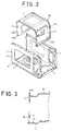
- an inner plate 10 as shown in Fig. 2, includes side walls 12 formed about an upper wall 11.
- An upper flange 11a is formed along the rim of the upper wall 11, and a side flange 12a is formed at the side of the side walls 12, and a lower flange 12b is formed at the lower surface of the side walls 12.
- Each of flanges 11a, 12a, and 12b includes spaced-apart embossing protrusions formed at the outer portion thereof.
- the inner plate 10 is fit to the outer plate 1.
- the lower flange 12b formed at a bottom wall of the outer plate 1 and the side walls of the inner plate 10 are assembled in the projection welding method or other welding methods, so that a component compartment 5 of the outer plate 1 and a door engaging section 6 are reinforced.
- this conventional microwave oven main body structure has advantages in that the component compartment 5 of the outer plate 1 and the door engaging section 6 are reinforced by permitting the bottom wall 2 of the outer plate 1 and the lower flanges 12b of the inner plate 10 to be engaged with each other, since a lower contact section 3a, as shown in Fig. 3, is formed at the front wall 3 of the outer plate 1 so as to prevent microwave leakages between the front wall 3 of the outer plate 1 and the door (not shown), a certain recess having the height "h" is provided between the lower contact section 3a of the outer plate 1 and the bottom wall 2, it is difficult to clean the interior of the microwave oven.
- Figs. 4 and 5 show another conventional microwave oven main body structure, which includes a front wall 32 and a rear wall 33 disposed at the front and rear sides of a bottom wall 31 of the outer plate 30, respectively.
- the bottom wall 31 of the outer plate 30 includes an opening 34 for receiving components.
- the inner plate 40 is three time curved and both ends thereof meet to each other.
- Flanges 41a, 42a, 43a, and 44a are formed at the front and rear rims of an upper wall 41, a lower wall 42, a left side wall 43, and a right side wall 44, respectively.
- a plurality of spaced-apart embossing protrusions are formed at the outer side of the flanges 41a, 42a, 43a, and 44a.
- the inner plate 40 is engaged to the interior of the outer plate 30.
- a cover 35 is engaged to the lower portion of the outer plate 30 so as to block the openings 34 formed at the outer plate 30.
- this conventional microwave oven main body structure has advantage in that the problem of the recess can be resolved, since the opening 34 is formed at the bottom wall 31 of the outer plate 30, when relatively heavy components are disposed in the system, the component compartment 36 and the door engaging section 37 can be easily deformed due to the over weight thereof.
- a reinforcing member must be additionally provided so as to support the frame.
- Figs. 6 through 8 show another conventional microwave oven main body structure, which includes an inner plate 52 which is three times curved at 90°.
- a curling section 54a is formed at the entire front rim portion of the inner plate 52, and a flange section 53a is formed at the entire rear rim portion of the inner plate 52.
- a plurality of spaced-apart embossing protrusions 53b are formed at the flange 53a of the side walls 53 of the inner plate 52.
- a window section 59 is formed at the front wall 55 of the outer plate 51 which is twice curved at 90°.
- a curling section 55a is formed at the inner surface of the outer plate 51, that is, at a periphery of the window section 59 opposed to the curling 54a of the inner plate 52.
- a plurality of engaging openings 56a are formed at the inner wall of the rear wall 56 opposing to the flange 53a of the inner plate 52.
- the rear portion of the flange 53a of the inner plate 52 is fixed to the rear wall 56 of the outer plate 51 in the calking method.
- the flange 53a of the inner plate 52 is fit to the rear wall 56 of the outer plate 51, and each of the embossing protrusions 53b of the inner plate 52 is fit to the interior of the engaging opening 51b of the outer plate 51, so that the embossing protrusions 53b are deformed by hitting using a puncher P the embossing protrusions 53b which passed through the engaging opening 56a of the outer plate 51, and the inner plate 52 is fixed to the outer plate 51.
- a microwave oven main body structure which includes an outer plate having a bottom wall, a front wall, and a rear wall; a support member formed on the bottom of the outer plate; and a front- and rear-portion-opened inner plate engaged to the interior of the outer plate and having an outwardly extended side wall; wherein the lower surface of a flange formed at the lower portion of the side wall of the inner plate which is downwardly extended contacts with the upper surface of the bottom of the outer plate.
- a microwave oven main body structure which includes an outer plate having a bottom wall, a front wall, and a rear wall; a plurality of support members formed at the bottom of the outer plate; and an inner plate fixed to the interior of the outer plate and having outwardly extended both ends formed at a contact portion of side walls.
- Fig. 1 is a perspective view showing a conventional microwave oven main body structure.
- Fig. 2 is an exploded perspective view showing a conventional microwave oven main body structure of Fig. 1.
- Fig. 3 is a partial side cross-sectional view of a conventional microwave oven main body structure.
- Fig. 4 is an exploded perspective view showing another conventional microwave oven main body structure.
- Fig. 5 is a side cross-sectional view of a conventional microwave oven main body structure of Fig. 4.
- Fig. 6 is a perspective view showing another conventional microwave oven main body structure.
- Fig. 7 is an exploded perspective view showing another conventional microwave oven main body structure.
- Fig. 8A is a cross-sectional view of an outer plate and an inner plate of a cavity before the outer and inner plate are assembled of another conventional microwave oven main body structure.
- Fig. 8B is a cross-sectional view of an outer plate and an inner plate before the outer and inner plates of a cavity are calked in another conventional microwave oven main body structure.
- Fig. 8C is a cross-sectional view of an outer plate and an inner plate after the outer and inner plates of a cavity are calked in another conventional microwave oven main body structure.
- Fig. 9 is an exploded perspective view showing a microwave oven main body structure of a first embodiment according to the present invention.
- Fig. 10 is a partial perspective view showing an engaging portion of a microwave oven main body structure of a first embodiment according to the present invention.
- Fig. 11 is a partial perspective view showing a microwave oven main body structure of a second embodiment according to the present invention.
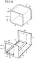
- Fig. 12 is an exploded perspective view showing a microwave oven main body structure of a third embodiment according to the present invention.
- Fig. 13A is a cross-sectional view showing an inner plate when both ends thereof contacts with each other of a microwave oven main body structure of a third embodiment according to the present invention.
- Fig. 13B is a cross-sectional view so as to show a calking process of both ends of an inner plate of a microwave oven main body structure of a third embodiment according to the present invention.
- Fig. 13C is a cross-sectional view so as to show a construction that both ends of an inner plate is plastic-deformed in a microwave oven main body structure of a third embodiment according to the present invention.
- Fig. 14 is a perspective view showing a calked portion of a cavity of a microwave oven main body of a third embodiment according to the present invention.
- Fig. 15 is a perspective view showing a curling structure of a cavity of a microwave oven main body structure of a third embodiment according to the present invention.
- Fig. 16 is a perspective view showing a microwave oven main body structure of a fourth embodiment according to the present invention.
- Fig. 17 is a perspective cross-sectional view showing a microwave oven main body structure of a fifth embodiment according to the present invention.
- Fig. 9 shows a microwave oven main body structure of a first embodiment according to the present invention, which includes an inner plate 160 which is curved three times at 90°.
- Flanges 161a, 162a, 163a, and 164a are formed at the entire front and rear rims of an upper wall 161, a lower wall 162, a left side wall 163, and a right side wall 164 of the inner plate 160.
- a front wall 152 and a rear wall 153 are formed at the bottom 151 of the outer plate 150, and a support member 100 is disposed at one side of the bottom 151.
- the support member 100 includes a vertical support wall 155 formed at one side of an opening 154 in the front and rear directions of the microwave oven main body, and a horizontal support wall 156 which is formed at the upper portion of the vertical support wall 155 and curved in the direction of the interior of the microwave oven main body.
- Part of the bottom of the inner plate 160 contacts with the upper surface of the horizontal support wall 156.
- a flange 167 is formed at one side of the lower plate 162 of the inner plate 160 and is welded to a predetermined inner portion of the side wall 164 of the inner plate 160.
- reference numeral 173 denotes a component compartment.
- the flange 168 formed at the recess of the lower wall 162 of the inner plate 160 is fixed to the inner surface of the side wall 164 of the inner plate 160 in the projection welding method or the like.
- the inner plate 160 is introduced into the interior of the outer plate 150.
- the flanges 161a, 162a, 163a, and 164a of the inner plate 160 contact with the inner surface of the front wall 152 and the rear wall 153 of the outer plate 150, and the inner plate 160 is fixed to the outer plate 150 in the projection welding method or the like.
- the upper surface of the bottom wall 151 of the outer plate 150 and the lower surface of the flange 167 formed at the lower portion of the side wall 164 of the inner plate 160 contact with each other, and welded in the projection welding method or the like, so that a microwave oven cavity is fabricated.
- the opening 154 is formed at the bottom wall 151 of the outer plate 150, it is possible to more easily assemble the inner plate 160 and the outer plate 150 in cooperation with the opening 154.
- a cover 135 is engaged to the bottom of the outer plate 150 so as to cover the opening 154 formed at the outer plate 150.
- Fig. 11 shows a microwave oven main body structure of a second embodiment according to the present invention, which is directed to exchanging the positions of the support member formed on the bottom wall 251 of the outer plate 250 and the position in which the inner plate 250 is fixed to the outer plate 250 of the first embodiment according to the present invention.
- Fig. 12 shows a microwave oven main body structure of a third embodiment according to the present invention, which is directed to calking and curing an outer plate 310 and an inner plate 320 for engaging the outer plate 310 and the inner plate 320 and provides a plurality of support members 200 at a front portion and a rear portion of a bottom wall 311 of the outer plate 310 so as to reinforce the inner plate 320 with respect to the outer plate 310.
- this embodiment is directed to calking in a surface-to-surface state, as compared to the previous embodiment of the present invention which is characterized to calking in a rugged state between the outer plate 310 and the inner plate 320, so that a more accurate engagement between the outer plate 310 and the inner plate 320 can be achieved.
- the front- and rear-portion-opened inner plate 320 is curved three times at 90° and includes an upper wall 321, a lower wall 322, a left side wall 323, and a right side wall 324.
- the contacting portion between the upper wall 321 of the inner plate 320 and the left side wall of the same includes end sections 325 and 326 extended outwardly by a predetermined length and calk-fixed to each other.
- flanges 327 and 328 are formed at the entire portion of the front and rear portion rims of the upper wall 320, the upper wall 321, the lower wall 322, the left side wall 323, and the right side wall 324 of the inner plate 320.
- a front wall 312 and a rear wall 313 are formed at the bottom 311 of the outer plate 310, and a support member 200 is formed at both sides of the bottom 311.
- the support member 200 of the third embodiment according to the present invention includes vertical support walls 314 and 315 spaced-apart in the directions of the front and rear portion of the microwave oven main body wherein the bottom surface 311 of the outer plate 310 is bent, and horizontal support walls 314a and 315a each inwardly curved in the direction of the interior of the microwave oven main body at the upper portion of the vertical support walls 314 and 315.
- the flange 328 of the inner plate 320 and the rear wall 313 of the outer plate 310 are calked and welded.
- the horizontal support walls 314a and 315a formed at the outer plate 310 and the periphery of the lower portion of the lower wall 322 of the inner plate 320 stably contact with each other, thus reinforcing the main body.
- Fig. 16 shows a microwave oven main body structure of a fourth embodiment according to the present invention, which includes vertical support walls 414 and 415 formed at both sides of the bottom 411 of the outer plate 410 for supporting the inner plate 420.
- Fig. 17 shows a microwave oven main body structure of a fifth embodiment according to the present invention, which includes vertical support walls 514 and 515 at both ends of the bottom 511 of the outer plate 510, and horizontal support walls 514a and 515a formed at the upper portion of the vertical support walls 514 and 515.
- the horizontal support walls 514a and 515a are curved outwardly so as to support the inner plate 520.
- the microwave oven main body structure according to the present invention is directed to reinforcing the component compartment and the door engaging section of the outer plate without using an additional reinforcing member by forming a support member at one side of the bottom of the outer plate so as to support the inner plate, extending downwardly the side wall of the inner plate which is not supported by the support member so that the side wall thereof can contact with the bottom wall of the outer plate, thus preventing a recess formation in the microwave oven main body.
- the present invention is further directed to improving the strength of the product by forming a plurality of support members at the bottom of the outer plate for supporting the inner plate so that the bottom of the inner plate can be supported by the support members. Moreover, a more stable engagement between the outer plate and the inner plate can be achieved by a deformation at the calking portion by calking the outer plate and the inner plate.
Landscapes
- Engineering & Computer Science (AREA)
- Physics & Mathematics (AREA)
- Electromagnetism (AREA)
- Chemical & Material Sciences (AREA)
- Combustion & Propulsion (AREA)
- Mechanical Engineering (AREA)
- General Engineering & Computer Science (AREA)
- Electric Ovens (AREA)
- Cookers (AREA)
- Package Specialized In Special Use (AREA)
- Constitution Of High-Frequency Heating (AREA)
Applications Claiming Priority (4)
| Application Number | Priority Date | Filing Date | Title |
|---|---|---|---|
| KR1019950012077A KR0152840B1 (ko) | 1995-05-16 | 1995-05-16 | 전자레인지의 캐비티 구조 |
| KR2019950010341U KR960038058U (ko) | 1995-05-16 | 1995-05-16 | 전자레인지의 캐비티 구조 |
| KR1207795 | 1995-05-16 | ||
| KR1034195 | 1995-05-16 |
Publications (1)
| Publication Number | Publication Date |
|---|---|
| EP0743491A1 true EP0743491A1 (fr) | 1996-11-20 |
Family
ID=26630995
Family Applications (1)
| Application Number | Title | Priority Date | Filing Date |
|---|---|---|---|
| EP96100104A Ceased EP0743491A1 (fr) | 1995-05-16 | 1996-01-05 | Structure du corps principal d'un four à micro-ondes |
Country Status (5)
| Country | Link |
|---|---|
| US (1) | US5818017A (fr) |
| EP (1) | EP0743491A1 (fr) |
| CN (1) | CN1107840C (fr) |
| BR (1) | BR9600180A (fr) |
| CA (1) | CA2166586C (fr) |
Cited By (2)
| Publication number | Priority date | Publication date | Assignee | Title |
|---|---|---|---|---|
| EP0803683A1 (fr) * | 1996-04-23 | 1997-10-29 | Samsung Electronics Co., Ltd. | Boîtier notamment pour un four à micro-onde |
| EP2026633A3 (fr) * | 2007-08-17 | 2013-07-31 | Samsung Electronics Co., Ltd. | Appareil de cuisson chauffant |
Families Citing this family (6)
| Publication number | Priority date | Publication date | Assignee | Title |
|---|---|---|---|---|
| KR100324507B1 (ko) * | 1997-11-15 | 2002-06-24 | 구자홍 | 전자레인지 |
| KR100306627B1 (ko) * | 1999-01-21 | 2001-09-24 | 윤종용 | 전자렌지 |
| US6827123B2 (en) * | 2003-02-06 | 2004-12-07 | Sandy Huang | Oven shell and method of fabricating same |
| KR20040096136A (ko) * | 2003-05-07 | 2004-11-16 | 삼성전자주식회사 | 제빵기 |
| KR100609174B1 (ko) * | 2003-10-16 | 2006-08-02 | 엘지전자 주식회사 | 전자레인지의 베이스 플레이트 구조 |
| CN105605633B (zh) * | 2016-02-25 | 2018-07-13 | 广东美的厨房电器制造有限公司 | 微波炉外壳及具有其的微波炉 |
Citations (4)
| Publication number | Priority date | Publication date | Assignee | Title |
|---|---|---|---|---|
| US4609801A (en) * | 1985-07-08 | 1986-09-02 | Whirlpool Corporation | Cavity construction for microwave oven |
| EP0301575A2 (fr) * | 1987-07-31 | 1989-02-01 | Matsushita Electric Industrial Co., Ltd. | Cavité chauffante pour four à micro-ondes |
| US4843204A (en) * | 1988-01-11 | 1989-06-27 | Sharp Kabushiki Kaisha | Microwave oven cavity housing |
| EP0394978A2 (fr) * | 1989-04-25 | 1990-10-31 | Sharp Kabushiki Kaisha | Cadre de construction pour four à micro-ondes et pareil |
Family Cites Families (5)
| Publication number | Priority date | Publication date | Assignee | Title |
|---|---|---|---|---|
| JPS60245930A (ja) * | 1984-05-18 | 1985-12-05 | Matsushita Electric Ind Co Ltd | 高周波加熱装置 |
| JPS60263024A (ja) * | 1984-06-11 | 1985-12-26 | Matsushita Electric Ind Co Ltd | 高周波加熱装置 |
| JPS60263018A (ja) * | 1984-06-11 | 1985-12-26 | Matsushita Electric Ind Co Ltd | 高周波加熱装置 |
| JPS616107U (ja) * | 1984-06-15 | 1986-01-14 | シャープ株式会社 | 電子レンジのオ−ブンの構造 |
| JPS616516A (ja) * | 1984-06-19 | 1986-01-13 | Matsushita Electric Ind Co Ltd | 高周波加熱装置 |
-
1996
- 1996-01-04 CA CA002166586A patent/CA2166586C/fr not_active Expired - Fee Related
- 1996-01-05 EP EP96100104A patent/EP0743491A1/fr not_active Ceased
- 1996-01-22 BR BR9600180A patent/BR9600180A/pt not_active Application Discontinuation
- 1996-01-22 CN CN96100877A patent/CN1107840C/zh not_active Expired - Fee Related
- 1996-01-29 US US08/593,250 patent/US5818017A/en not_active Expired - Fee Related
Patent Citations (4)
| Publication number | Priority date | Publication date | Assignee | Title |
|---|---|---|---|---|
| US4609801A (en) * | 1985-07-08 | 1986-09-02 | Whirlpool Corporation | Cavity construction for microwave oven |
| EP0301575A2 (fr) * | 1987-07-31 | 1989-02-01 | Matsushita Electric Industrial Co., Ltd. | Cavité chauffante pour four à micro-ondes |
| US4843204A (en) * | 1988-01-11 | 1989-06-27 | Sharp Kabushiki Kaisha | Microwave oven cavity housing |
| EP0394978A2 (fr) * | 1989-04-25 | 1990-10-31 | Sharp Kabushiki Kaisha | Cadre de construction pour four à micro-ondes et pareil |
Cited By (3)
| Publication number | Priority date | Publication date | Assignee | Title |
|---|---|---|---|---|
| EP0803683A1 (fr) * | 1996-04-23 | 1997-10-29 | Samsung Electronics Co., Ltd. | Boîtier notamment pour un four à micro-onde |
| US5938967A (en) * | 1996-04-23 | 1999-08-17 | Samsung Electronics Co., Ltd. | Casing structure of a microwave oven |
| EP2026633A3 (fr) * | 2007-08-17 | 2013-07-31 | Samsung Electronics Co., Ltd. | Appareil de cuisson chauffant |
Also Published As
| Publication number | Publication date |
|---|---|
| CN1136156A (zh) | 1996-11-20 |
| CN1107840C (zh) | 2003-05-07 |
| US5818017A (en) | 1998-10-06 |
| CA2166586A1 (fr) | 1996-11-17 |
| BR9600180A (pt) | 1997-10-07 |
| CA2166586C (fr) | 1999-12-14 |
Similar Documents
| Publication | Publication Date | Title |
|---|---|---|
| US5818017A (en) | Microwave oven main body structure | |
| US5568712A (en) | Refrigerator door construction | |
| US20030107235A1 (en) | Door for vehicle and its manufacturing method | |
| JPH0514485B2 (fr) | ||
| US7152911B1 (en) | Vehicle bed and cross rail attachment | |
| CN105905167B (zh) | 车辆车身结构 | |
| WO2006040732A1 (fr) | Structure de chassis de corps pour vehicule automobile | |
| US20080012390A1 (en) | Structural part for the body or undercarriage of a motor vehicle | |
| KR20020077018A (ko) | 차체 구조 | |
| US4826040A (en) | Refrigeration cabinet construction | |
| US4381842A (en) | Metal enclosure and manufacturing method therefor | |
| US4826010A (en) | Refrigeration cabinet construction | |
| JP2000255451A (ja) | 自動車の前部車体構造 | |
| JP2002053067A (ja) | 車体の骨格構造 | |
| US6464286B2 (en) | Door or other body part of a motor vehicle | |
| EP0251782A1 (fr) | Assemblages pour enveloppes d'appareils ménagers et de telles enveloppes | |
| JP2878637B2 (ja) | 洗濯機の内槽およびその製造方法 | |
| GB2032354A (en) | Panel | |
| CN110691544A (zh) | 冲洗容器、家用洗碗机和方法 | |
| JP3445060B2 (ja) | 床点検口 | |
| KR0152840B1 (ko) | 전자레인지의 캐비티 구조 | |
| JP4347750B2 (ja) | 排水溝用ふた部材およびそれを用いた排水溝用ふた | |
| JPH0156851B2 (fr) | ||
| JP2715908B2 (ja) | 脚 | |
| JP2940473B2 (ja) | クロスメンバの取付構造 |
Legal Events
| Date | Code | Title | Description |
|---|---|---|---|
| PUAI | Public reference made under article 153(3) epc to a published international application that has entered the european phase |
Free format text: ORIGINAL CODE: 0009012 |
|
| 17P | Request for examination filed |
Effective date: 19960112 |
|
| AK | Designated contracting states |
Kind code of ref document: A1 Designated state(s): DE FR GB |
|
| 17Q | First examination report despatched |
Effective date: 19970930 |
|
| GRAG | Despatch of communication of intention to grant |
Free format text: ORIGINAL CODE: EPIDOS AGRA |
|
| STAA | Information on the status of an ep patent application or granted ep patent |
Free format text: STATUS: THE APPLICATION HAS BEEN REFUSED |
|
| 18R | Application refused |
Effective date: 19990404 |