EP0396030B1 - Dispositif de chauffage pour une machine travaillant les matières plastiques - Google Patents
Dispositif de chauffage pour une machine travaillant les matières plastiques Download PDFInfo
- Publication number
- EP0396030B1 EP0396030B1 EP90108018A EP90108018A EP0396030B1 EP 0396030 B1 EP0396030 B1 EP 0396030B1 EP 90108018 A EP90108018 A EP 90108018A EP 90108018 A EP90108018 A EP 90108018A EP 0396030 B1 EP0396030 B1 EP 0396030B1
- Authority
- EP
- European Patent Office
- Prior art keywords
- temperature control
- control means
- loop
- shells
- bending
- Prior art date
- Legal status (The legal status is an assumption and is not a legal conclusion. Google has not performed a legal analysis and makes no representation as to the accuracy of the status listed.)
- Expired - Lifetime
Links
Images




Classifications
-
- B—PERFORMING OPERATIONS; TRANSPORTING
- B29—WORKING OF PLASTICS; WORKING OF SUBSTANCES IN A PLASTIC STATE IN GENERAL
- B29C—SHAPING OR JOINING OF PLASTICS; SHAPING OF MATERIAL IN A PLASTIC STATE, NOT OTHERWISE PROVIDED FOR; AFTER-TREATMENT OF THE SHAPED PRODUCTS, e.g. REPAIRING
- B29C45/00—Injection moulding, i.e. forcing the required volume of moulding material through a nozzle into a closed mould; Apparatus therefor
- B29C45/17—Component parts, details or accessories; Auxiliary operations
- B29C45/72—Heating or cooling
- B29C45/74—Heating or cooling of the injection unit
-
- B—PERFORMING OPERATIONS; TRANSPORTING
- B29—WORKING OF PLASTICS; WORKING OF SUBSTANCES IN A PLASTIC STATE IN GENERAL
- B29C—SHAPING OR JOINING OF PLASTICS; SHAPING OF MATERIAL IN A PLASTIC STATE, NOT OTHERWISE PROVIDED FOR; AFTER-TREATMENT OF THE SHAPED PRODUCTS, e.g. REPAIRING
- B29C48/00—Extrusion moulding, i.e. expressing the moulding material through a die or nozzle which imparts the desired form; Apparatus therefor
- B29C48/25—Component parts, details or accessories; Auxiliary operations
- B29C48/78—Thermal treatment of the extrusion moulding material or of preformed parts or layers, e.g. by heating or cooling
- B29C48/80—Thermal treatment of the extrusion moulding material or of preformed parts or layers, e.g. by heating or cooling at the plasticising zone, e.g. by heating cylinders
- B29C48/83—Heating or cooling the cylinders
-
- B—PERFORMING OPERATIONS; TRANSPORTING
- B29—WORKING OF PLASTICS; WORKING OF SUBSTANCES IN A PLASTIC STATE IN GENERAL
- B29C—SHAPING OR JOINING OF PLASTICS; SHAPING OF MATERIAL IN A PLASTIC STATE, NOT OTHERWISE PROVIDED FOR; AFTER-TREATMENT OF THE SHAPED PRODUCTS, e.g. REPAIRING
- B29C48/00—Extrusion moulding, i.e. expressing the moulding material through a die or nozzle which imparts the desired form; Apparatus therefor
- B29C48/25—Component parts, details or accessories; Auxiliary operations
- B29C48/78—Thermal treatment of the extrusion moulding material or of preformed parts or layers, e.g. by heating or cooling
- B29C48/80—Thermal treatment of the extrusion moulding material or of preformed parts or layers, e.g. by heating or cooling at the plasticising zone, e.g. by heating cylinders
- B29C48/83—Heating or cooling the cylinders
- B29C48/832—Heating
-
- B—PERFORMING OPERATIONS; TRANSPORTING
- B29—WORKING OF PLASTICS; WORKING OF SUBSTANCES IN A PLASTIC STATE IN GENERAL
- B29C—SHAPING OR JOINING OF PLASTICS; SHAPING OF MATERIAL IN A PLASTIC STATE, NOT OTHERWISE PROVIDED FOR; AFTER-TREATMENT OF THE SHAPED PRODUCTS, e.g. REPAIRING
- B29C48/00—Extrusion moulding, i.e. expressing the moulding material through a die or nozzle which imparts the desired form; Apparatus therefor
- B29C48/25—Component parts, details or accessories; Auxiliary operations
- B29C48/78—Thermal treatment of the extrusion moulding material or of preformed parts or layers, e.g. by heating or cooling
- B29C48/80—Thermal treatment of the extrusion moulding material or of preformed parts or layers, e.g. by heating or cooling at the plasticising zone, e.g. by heating cylinders
- B29C48/83—Heating or cooling the cylinders
- B29C48/834—Cooling
-
- B—PERFORMING OPERATIONS; TRANSPORTING
- B29—WORKING OF PLASTICS; WORKING OF SUBSTANCES IN A PLASTIC STATE IN GENERAL
- B29C—SHAPING OR JOINING OF PLASTICS; SHAPING OF MATERIAL IN A PLASTIC STATE, NOT OTHERWISE PROVIDED FOR; AFTER-TREATMENT OF THE SHAPED PRODUCTS, e.g. REPAIRING
- B29C48/00—Extrusion moulding, i.e. expressing the moulding material through a die or nozzle which imparts the desired form; Apparatus therefor
- B29C48/03—Extrusion moulding, i.e. expressing the moulding material through a die or nozzle which imparts the desired form; Apparatus therefor characterised by the shape of the extruded material at extrusion
- B29C48/09—Articles with cross-sections having partially or fully enclosed cavities, e.g. pipes or channels
Definitions
- the invention relates to a temperature control device on a plastics processing machine in accordance with the preamble of patent claim 1.
- Temporing device in the sense of the preamble is understood to be a device that is capable of supplying or removing such an amount of heat from the plasticizing cylinder in a timely manner that the temperatures required according to the work program of the machine are continuously achieved.
- tube-like temperature control element is understood to mean an energy-supplying or an energy-extracting element.
- it is a resistance heating tube deformed by bending, in which at least one resistance wire is embedded approximately centrally by means of an electrically insulating, but good heat-conducting powder (for example silicate powder).
- it is a metal pipe that is suitable for the flow of a liquid cooling medium.
- a radial and staggered arrangement of coolants and heating means also have known (DE-AS 1 149 161) heating sleeves for plastics processing machines, in which the heating means are provided by screw-like, tubular heating resistor elements which are cast into the heating sleeve and completely enclose the plasticizing cylinder are formed.
- the heating means are provided by screw-like, tubular heating resistor elements which are cast into the heating sleeve and completely enclose the plasticizing cylinder are formed.
- a division into half-shells and thus a radial pressing of their contact surfaces onto the plasticizing cylinder is not the case with these heating jackets possible.
- these closed metal sleeves are pressed axially onto the press cylinder by means of appropriate devices with a correspondingly small internal width using considerable forces. A quick exchange of the temperature control agent for repair and service purposes is then no longer possible.
- DE 34 28 539 A1 also discloses a heating sleeve for heating tubular objects, in particular injection nozzles of plastic injection molding machines.
- This consists of one or more rectangular metallic plates with parallel grooves in which heating cartridges are inserted.
- the plates are bent into semicircular cylindrical shells in such a way that the grooves on the concavely curved inner surface run parallel to the cylinder axis.
- the dimension of the heating sleeve in the radial direction can be dimensioned relatively small and its mass can be kept low.
- the heating cartridges inevitably lie directly on the tubular object to be heated. On the one hand, this results in overheated zones in the object to be tempered along the heating cartridges lying thereon.
- the grooves receiving the heating cartridges reduce the internal contact area of the plates, which is why the heat transfer from the bodies of the plates to the object to be heated is restricted. In this respect, a sufficiently uniform heat transfer to the object to be heated is not guaranteed for a strict temperature control.
- the invention has for its object to develop a temperature control device of the type mentioned in such a way that it ensures a quicker temperature control thanks to a relatively small wall thickness of the relatively flexible temperature control shells and a more intensive contact that can be achieved thereby with inexpensive production.
- the quotient shell thickness / diameter of the tubular temperature control element is approximately 2.
- the wall of the shell is therefore only twice as thick as the diameter of the temperature control element or is even thinner, without the contact surface being appreciably restricted.
- the molten metal for example aluminum
- the temperature control element is absolutely securely clamped between the mold halves. Clamping in this way ensures that the temperature control element does not change its position despite the strong exposure to the liquid metal flowing in at high speed.
- An extremely high injection speed is required because, due to the relatively small mold cavity, only a small amount of metal is required to form the shell, which is subject to rapid cooling due to the relatively large inner surface of the mold cavity. It is therefore necessary to design the injection process so that it is in the Usually ended in a span of seconds.
- the invention dispenses with a pairing of coolants and heating means in the same temperature control device and is limited to a single meandering curved temperature control element in each of the temperature control shells that can be radially pressed onto the plasticizing cylinder.
- a post-processing of the tempering bowl by time-consuming grinding or milling is therefore usually not necessary.
- the open support surfaces of the temperature control element rest on corresponding rib-like or cylindrical shapes of the inner walls of the casting mold for fixing.
- the recesses mentioned in claim 1 represent the negatives of the mentioned forms.
- Claims 8 and 9 relate to processes for the production of temperature control shells, each with a meandering temperature control element cast into metal. It has been shown that with a heat-supplying tube-like temperature control element (resistance heating tube), in which the bent sections of the loops are not symmetrical to one plane, permanent deformation is difficult in many cases. This is particularly the case if the curved sections (13b) are additionally bent perpendicular to this plane to adapt to the radius of the object to be heated (as is the case, for example, with the resistance heating tube 29 in FIG. 2.6 of US Pat. No. 3,317,958). After the loops have been bent twice in the area of their curved sections, considerable and different springback tendencies often become noticeable.
- resistance heating tube resistance heating tube
- the processes for the production of the temperature control shells in the combination of their process steps are essentially characterized by their need to bend tubular, linear temperature control elements in such a meandering manner that they can be inserted into the mold cavity of a casting mold for the production of half shells and without any significant springback tendencies.
- the process variants according to the invention differ fundamentally from known bending processes (DE-A-2 236 898; US-A-4 112 728; US-A-2 851 082), in which the meandering bending of linear tubes takes place only in a single plane .
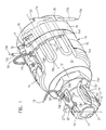
- the temperature control device on the plasticizing cylinder and on the nozzle of a plastic injection molding machine is shown.
- the temperature control device on the plasticizing cylinder is first dealt with:
- An essential component of the temperature control device are sleeves constructed from two temperature control shells 14, which enclose the plasticizing cylinder 10. According to the length of the plasticizing cylinder 10, several sleeves are axially strung together on the plasticizing cylinder 10. From the drawing only the sleeve adjacent to the nozzle can be seen.
- the shells 14 each have an inner circumferential surface as a contact surface 14g and an outer circumferential surface which is approximately concentric with the contact surface.
- the two shells 14 of a cuff can be pressed onto the jacket surface to be tempered with the aid of two releasable tensioning straps 15.
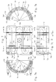
- a single temperature control element is cast, which is formed from a linear tube in such a way that it has several loops 13 each with two linear sections 13a and a curved section 13b. Each loop 13 lies approximately symmetrically to a surface line cc of the plasticizing cylinder 10.
- Each temperature control element has free, that is to say uncovered by the cast metal, support surfaces 13e. At these openings 14e, 14f (Fig. 7,7a-7c, 9,14) open, which start from the inner and outer surface of the associated shell 14.
- the metal forming the surface of the temperature control element is at least in the region of the support surfaces 13e, 13e 'in the electrochemical Voltage series as high or higher than the metal in which the temperature control element is cast.
- the loops 13 of the meandering temperature control element are arranged in planes ee (FIGS. 3,4,7a, 7b) standing at an obtuse angle to one another and perpendicular to radial ss of the plasticizing cylinder 10.
- the distance z (FIG. 3a) of the curved section 13b from the outer lateral surface, which is reduced in the radial ss, is several times greater than the corresponding distance p (FIG. 3a) from the inner lateral surface.
- the inner recesses 14e which extend from the inner lateral surface of the shells 14, are axially offset relative to one another with respect to the outer recesses 14f, which extend from the outer lateral surface.
- the dislocation distance r is shown in FIGS. 6 and 7 recognizable.
- the groove-like recesses 14e, 14f are arranged in planes yy perpendicular to the spray axis bb.
- the linear sections 13a of the loops 13 each adjoin at least two inner and two outer recesses.
- the tensioning straps 15 can be tensioned by means of a tensioning bolt 17 and by means of bearing bolts 16. During assembly, the tensioning straps 15 are guided or axially fixed on projections 14d.
- the straps can be fixed in the circumferential direction by means of locking pins 20.
- the joints between the two shells 14 of the sleeves lie in a horizontal plane (joint plane tt in Fig. 3.4).
- the upper shell 14 of a sleeve has an opening 22 for a thermal sensor 18.
- the thermal sensor 18 is held by a hollow banjo bolt 19, in which it is axially adjustable by means of a spiral spring. Since an internal thread of the hollow fastening screw 19 'engages in the spring spiral, the spring spiral supported on a shoulder of the thermocouple 18' can be biased by rotating the hollow fastening screw 19 ', thereby axially loading the thermocouple.
- the temperature control device on the nozzle is described below:
- the two shells 14 ' are provided which complement each other to form a cuff.
- the sleeve is pressed onto the lateral surface of the nozzle 11 by means of a single tensioning band 15 '.
- the joints 27 of the two shells 14 ' lie in a vertical plane (joint plane t'-t' in Fig. 1.3).
- the free linear connection ends 13c ' (FIGS. 1-11 and 13' '' in FIGS. 12-16) each run perpendicular to the joint plane t'-t '.
- the two temperature control elements each have a single loop 13 '(FIGS. 8-11; 13-16).
- a passage opening 22 'for a thermal sensor 18 is formed in the vertical joint 27 by corresponding cutouts in the shells 14'.
- the thermal sensor 18 is held by means of a holding element 21 '.
- the holding element 21 ' is part of the tensioning strap 15'.
- the thermal sensor can be axially loaded by means of a spiral.
- the shells have molded portions 14h 'which bear against a radial shoulder 12b' of a hollow screw 12.
- the nozzle body is connected to the plasticizing cylinder 10 by means of the hollow screw 12.
- the strap 15 ' is arranged in a front portion of the nozzle in front of the hollow screw 19' for the thermocouple 18.
- the curved section 13b ' lies with the two linear sections 13a' in a vertical plane.
- the recesses 14e ', 14f' are cylindrical channels.
- the tensioning strap 15c ' is arranged in a rear section of the nozzle and is therefore located in the region of the thermal sensor 18.
- the hollow banjo screw 19' therefore passes through the tensioning strap 15 'via a recess which delimits front and rear by narrow webs of the tensioning strap 15' is, as in particular from FIGS. 13 to 16, the curved section 13b 'of the temperature control element is bent outwards from the vertical plane in which the linear sections lie, in adaptation to the radius of the cylindrical nozzle body.
- the temperature control elements are designed as resistance heating elements
- the cooling medium is supplied or discharged via the free connection ends 13c '' of the cooling tubes of the shells 14 on the plasticizing cylinder 10 or via the free connection ends 13c '' 'of the cooling tube KR at the nozzle 11.
- FIG. 18 shows a design of the loops with which a higher heating power per unit area can be achieved
- FIG. 17 has an arrangement of the loops which allows a preferred transfer of the heating power at certain points.
- the loops 13 are symmetrical about surface lines c-c. By winding the resistance wire in the tube 13f, it is possible to significantly increase the heating power. In this case there are larger diameters of the temperature control elements. No heat is generated in the free connection ends 13c, 13c 'of the temperature control elements designed as heating pipes.
- the cuts are at a distance from one another which corresponds to the distance r in the FIGS. 6 and 7c.
- the cuts lie in planes which correspond to the planes yy of the recesses 14f and 14e in the finished tempering tray according to FIGS. 7a and 7b correspond. Accordingly, only the rib-like formations 40a ', 40b' acting on the inside support surfaces 13e and in Fig. 20 only on the outside support surfaces 13f of the temperature control element can be seen.
- Each rib-like shape 40a ', 40b' extends with a radius corresponding to the subsequent tempering shell in a semicircle on the wall of the mold halves 40a, 40b delimiting the mold cavity.
- Figs. 21, 22a, 22b illustrate the process steps for producing the temperature control elements on the basis of schematics, which individual process statuses VA; VB; VC; VD; Represent VE VF in the procedure.
- the temperature control element shown schematically is shown in front view and in side view. The same applies to the process states VA, VB, VC and VD in FIGS. 22a, 22b
- the method can be continued to add further loops in the sense of the previous method steps, with the direction of rotation being changed in each further method step with rotation about the axis of rotation f-f.
- a stationary bending device 25 bends alternately to one and the other side in a single bending plane B 'and that the not yet deformed, more or less long, free end of the temperature control element is intermittently in the bending position in the bending device 25 is retracted.
- the latter happens in that a holding device H in its axis of rotation ss alternately axially shifted in one direction or another by about the length of a loop and rotated by a central angle Alpha ', the temperature control element held eccentrically in the holding device H on a circular line emotional.
- the angle alpha is the acute angle that is formed between the planes e-e of two adjacent loops of the finished temperature control element (FIGS. 3; 22a, 22b).
- the size of the center angle Alpha ' depends on the number of loops of the temperature control element.
Landscapes
- Engineering & Computer Science (AREA)
- Mechanical Engineering (AREA)
- Physics & Mathematics (AREA)
- Thermal Sciences (AREA)
- Manufacturing & Machinery (AREA)
- Injection Moulding Of Plastics Or The Like (AREA)
- Extrusion Moulding Of Plastics Or The Like (AREA)
- Bending Of Plates, Rods, And Pipes (AREA)
- Processing And Handling Of Plastics And Other Materials For Molding In General (AREA)
- Control Of Temperature (AREA)
Claims (9)
- Dispositif d'équilibrage de température pour un cylindre de plastification (10), pourvu d'une buse (11), d'une machine de transformation de matières plastiques, avec des coques (14; 14') en métal moulé, qui présentent chacune une face d'enveloppe intérieure comme face de contact (14g) ainsi qu'une face d'enveloppe extérieure approximativement concentrique à la face de contact (14g) et qui peuvent être pressées sur la face d'enveloppe à équilibrer en température du cylindre de plastification (10) ou de la buse (11) au moyen de bandes de serrage (15), deux coques (14; 14') se complétant chaque fois en une manchette entourant la face d'enveloppe à équilibrer en température, et avec des éléments d'équilibrage de température pris au moulage dans les coques (14; 14'), qui sont façonnés à partir de tubes linéaires de telle sorte qu'ils présentent chacun au moins une boucle (13) avec deux parties linéaires (13a) et une partie coudée (13b), boucle qui est disposée approximativement symétriquement à une génératrice (c-c) du cylindre de plastification (10), des éléments d'équilibrage de température en méandres étant présents sur le cylindre de plastification (10), éléments qui présentent chacun plusieurs boucles (13) qui sont disposées dans des plans (e-e) situés sous un angle obtus les uns par rapport aux autres et perpendiculairement à la radiale (s-s) du cylindre de plastification,
caractérisé en ce qu'un seul élément d'équilibrage de température est pris au moulage dans chacune des coques (14; 14'), élément qui présente des faces d'appui (13e, 13e') dépourvues de métal moulé (non recouvertes de métal moulé), sur lesquelles débouchent des évidements (14e, 14f; 14e', 14f') qui partent de la face d'enveloppe intérieure et de la face d'enveloppe extérieure des coques (14; 14'), la distance (z), prise sur la radiale (s-s), de la partie coudée (13b) de la boucle (13) à la face d'enveloppe extérieure étant supérieure à la distance correspondante (p) à la face d'enveloppe intérieure. - Dispositif d'équilibrage de température selon la revendication 1, caractérisé en ce que le métal constituant la surface de l'élément d'équilibrage de température, au moins dans la région des faces d'appui (13e; 13e'), se situe aussi haut ou plus haut, dans la série électrochimique des tensions, que le métal dans lequel l'élément d'équilibrage de température est pris au moulage.
- Dispositif d'équilibrage de température selon la revendication 1 ou 2, caractérisé en ce que des évidements intérieurs (14e; 14e'), qui s'étendent à partir de la face d'enveloppe intérieure des coques (14; 14'), sont axialement décalés par rapport à des évidements extérieurs (14f; 14f'), qui s'étendent à partir de la face d'enveloppe extérieure, les parties linéaires (13a) des boucles (13) étant, sur le cylindre de plastification (10), chacune limitrophes d'au moins deux évidements intérieurs et deux évidements extérieurs.
- Dispositif d'équilibrage de température selon l'une des revendications précédentes, caractérisé en ce que les joints (26) entre les deux coques (14) des manchettes pour le cylindre de plastification (10) se situent dans un plan de joint horizontal (t-t), et les joints (27) des deux coques (14') de la manchette pour la buse (11) se situent dans un plan de joint vertical (t'-t'), les extrémités linéaires libres de raccordement (13c, 13c', 13c'', 13c''') des éléments d'équilibrage de température s'étendant respectivement perpendiculairement au plan de joint (t-t ; t't').
- Dispositif d'équilibrage de température selon l'une des revendications précédentes, caractérisé en ce que les deux éléments d'équilibrage de température pour la buse (11) présentent chacun une seule boucle (13').
- Dispositif d'équilibrage de température selon l'une des revendications 4 ou 5, caractérisé en ce qu'une ouverture de passage (22') pour un capteur de température (18') est formée dans le joint vertical (27) sur la buse (11) par des évidements correspondants dans les coques (14'), et ce capteur peut être déplacé axialement et est maintenu au moyen d'un élément de maintien (21'), fixé sur une bande de serrage (15') et traversé par une goupille de serrage (17'), ainsi qu'au moyen d'un boulon de fixation creux (19').
- Dispositif d'équilibrage de température selon l'une des revendications précédentes, caractérisé en ce que les deux coques identiques (14') sur la buse (11) présentent chacune une formation (14k') faisant saillie de leur face de contact (14g') vers l'intérieur, qui s'engage derrière un épaulement vertical de la buse (11).
- Procédé de fabrication de coques (14) pour un dispositif d'équilibrage de température sur le cylindre de plastification selon l'une des revendications 1 à 4, selon lequel des éléments potentiels d'équilibrage de température, tubulaires et linéaires, sont déformés en éléments d'équilibrage de température en méandres en formant plusieurs boucles (13) qui présentent chacune une partie coudée (13b) et deux parties linéaires (13a),
par le fait qu'on maintient un élément potentiel linéaire d'équilibrage de température à rotation autour de son axe en formant un axe de rotation (f-f) et à translation axiale dans une direction de translation (V), et on le recourbe à une extrémité libre à 180° dans une direction déterminée de cintrage (B) au moyen d'un dispositif de cintrage (25), formant ainsi une première boucle (13), par le fait que l'élément d'équilibrage de température déformé à une extrémité est ensuite déplacé axialement dans l'axe de rotation (f-f) de la longueur d'une boucle dans la direction de translation (V), et tourné autour de l'axe de rotation (f-f) dans le sens horaire ou anti-horaire d'un angle au centre de 180° plus un angle aigu alpha, qui est formé entre les plans (e-e) de boucles voisines, et on recourbe ensuite à 180° dans la direction de cintrage (B) l'extrémité déformée de l'élément d'équilibrage de température présentant la première boucle (13), formant ainsi une deuxième boucle (13'), puis on déplace à nouveau axialement de la longueur d'une boucle dans l'axe de rotation (f-f) l'élément d'équilibrage de température ainsi déformé, et on le tourne autour de l'axe de rotation (f-f) dans le sens anti-horaire ou horaire d'un angle au centre de 180° plus l'angle alpha,
et par le fait qu'on recourbe à 180° à l'aide du dispositif de cintrage (25) l'extrémité de l'élément d'équilibrage de température présentant la première boucle (13) et la deuxième boucle (13'), formant ainsi une troisième boucle (13''), et ainsi de suite, et ces éléments d'équilibrage de température sont ensuite pris au moulage dans du métal au moyen de moules (40) dont la forme creuse correspond chaque fois à une coque (14), l'élément d'équilibrage de température en méandres étant bloqué par serrage dans le moule (40) entre des formations (40a', 40b') des demi-moules (40a, 40b), lesquelles pénètrent dans la cavité de moule (41) et atteignent l'élément d'équilibrage de température dans la région de faces d'appui (13e) diamétralement opposées, et on injecte ensuite le métal liquide dans la cavité de moule (41) à une pression d'injection comprise entre 5.10⁷ et 13.10⁷ Pa (500 et 1300 bars) et en une durée d'au plus six secondes. - Procédé de fabrication de coques (14) pour un dispositif d'équilibrage de température sur le cylindre de plastification selon l'une des revendications 1 à 4, selon lequel des éléments potentiels d'équilibrage de température, tubulaires et linéaires, sont déformés en éléments d'équilibrage de température en méandres en formant plusieurs boucles (13) qui présentent chacune une partie coudée (13b) et deux parties linéaires (13a),
par le fait qu'on accomplit les étapes de procédé suivantes :
un élément linéaire et tubulaire d'équilibrage de température est, dans un bâti de maintien (H) qui est rotatif autour d'un axe de rotation (s-s) et déplaçable axialement dans cet axe de rotation dans des directions mutuellement opposées (Vr, Vl), maintenu excentriquement à l'axe de rotation (s-s), en étant reçu dans une position prête au cintrage dans un dispositif de cintrage stationnaire (25) ;
l'élément d'équilibrage de température ainsi maintenu est recourbé à une extrémité à 180° dans un plan de cintrage (B') au moyen du dispositif de cintrage (25), formant ainsi une première boucle (13) ;
l'élément d'équilibrage de température ainsi partiellement déformé est translaté conjointement avec le dispositif de maintien approximativement de la longueur d'une boucle (13) parallèlement à l'axe de rotation (s-s) dans une direction de translation (Vr) et, par suite d'une rotation avec le dispositif de maintien (H) d'un angle au centre (alpha') autour de l'axe de rotation (s-s), déplacé sur une trajectoire circulaire (K) de telle sorte que la partie linéaire non encore déformée (13n) de l'élément d'équilibrage de température est reçue dans une position prête au cintrage par le dispositif de cintrage (25) ;
l'élément d'équilibrage de température est recourbé à 180° à l'extrémité non déformée dans le plan de cintrage (B') dans une direction qui est opposée à la direction de cintrage lors de la formation de la première boucle (13), formant ainsi une deuxième bouche (13');
l'élément d'équilibrage de température ainsi déformé est translaté conjointement avec le dispositif de maintien approximativement de la longueur d'une bouche (13) parallèlement à l'axe de rotation (s-s) dans la direction de translation opposée (Vl) et, par suite d'une rotation avec le dispositif de maintien d'un angle au centre (alpha') autour de l'axe de rotation (s-s), déplacé sur une trajectoire circulaire (K) de telle sorte que sa partie linéaire non encore déformée (13n) est reçue dans une position prête au cintrage par le dispositif de cintrage (25) ;
l'élément d'équilibrage de température est recourbé à 180° à l'extrémité non déformée dans le plan de cintrage (B') dans une direction qui est opposée à la direction de cintrage lors de la formation de la deuxième boucle (13'), formant ainsi une troisième boucle (13'');
ces éléments d'équilibrage de température sont ensuite pris au moulage dans du métal au moyen de moules (40) dont la forme creuse correspond chaque fois à une coque (14), l'élément d'équilibrage de température en méandres étant bloqué par serrage dans le moule (40) entre des formations (40a', 40b') des demi-moules (40a, 40b), lesquelles pénètrent dans la cavité de morne (41) et atteignent l'élément d'équilibrage de température dans la région de faces d'appui (13e) diamétralement opposées, et on injecte ensuite le métal liquide dans la cavité de moule (41) à une pression d'injection comprise entre 5.10⁷ et 13.10⁷ Pa (500 et 1300 bars) et en une durée d'au plus six secondes.
Applications Claiming Priority (4)
| Application Number | Priority Date | Filing Date | Title |
|---|---|---|---|
| DE3914742 | 1989-05-05 | ||
| DE3914742 | 1989-05-05 | ||
| EP89115780 | 1989-08-26 | ||
| EP89115780 | 1989-08-26 |
Publications (3)
| Publication Number | Publication Date |
|---|---|
| EP0396030A2 EP0396030A2 (fr) | 1990-11-07 |
| EP0396030A3 EP0396030A3 (fr) | 1991-12-04 |
| EP0396030B1 true EP0396030B1 (fr) | 1995-08-16 |
Family
ID=25880574
Family Applications (1)
| Application Number | Title | Priority Date | Filing Date |
|---|---|---|---|
| EP90108018A Expired - Lifetime EP0396030B1 (fr) | 1989-05-05 | 1990-04-27 | Dispositif de chauffage pour une machine travaillant les matières plastiques |
Country Status (6)
| Country | Link |
|---|---|
| US (1) | US5157241A (fr) |
| EP (1) | EP0396030B1 (fr) |
| JP (1) | JP2795966B2 (fr) |
| AT (1) | ATE126474T1 (fr) |
| CA (1) | CA2015886C (fr) |
| DE (1) | DE59009524D1 (fr) |
Families Citing this family (7)
| Publication number | Priority date | Publication date | Assignee | Title |
|---|---|---|---|---|
| US5459811A (en) * | 1994-02-07 | 1995-10-17 | Mse, Inc. | Metal spray apparatus with a U-shaped electric inlet gas heater and a one-piece electric heater surrounding a nozzle |
| DE4404031C1 (de) * | 1994-02-09 | 1995-01-19 | Werner & Pfleiderer | Gehäuseabschnitt mit elektrischen Heizelementen für eine zweiwellige Schneckenmaschine |
| AT503222B1 (de) * | 2006-01-30 | 2008-07-15 | Smk Metall U Kunststoffwaren G | Heiz- und kühlvorrichtung |
| JP2008120417A (ja) * | 2006-11-10 | 2008-05-29 | Koyo Autom Mach Co Ltd | ラベリングマシン |
| US8395096B2 (en) * | 2009-02-05 | 2013-03-12 | Sandvik Thermal Process, Inc. | Precision strip heating element |
| US10596759B2 (en) * | 2017-10-25 | 2020-03-24 | Chromalox, Inc. | Extrusion assembly for an additive manufacturing system |
| JP6867360B2 (ja) * | 2018-12-10 | 2021-04-28 | リョービ株式会社 | ダイカスト用部品 |
Family Cites Families (17)
| Publication number | Priority date | Publication date | Assignee | Title |
|---|---|---|---|---|
| US2851082A (en) * | 1954-03-01 | 1958-09-09 | Reynolds Metals Co | Apparatus for making serpentine tube heat exchanger by twisting one or more runs |
| DE1149161B (de) * | 1959-12-18 | 1963-05-22 | Kloeckner Humboldt Deutz Ag | Rohrmantelheizkoerper fuer Schneckenstrangpressen zur Verarbeitung thermoplastischer Kunststoffe |
| US3370262A (en) * | 1963-05-27 | 1968-02-20 | Sprague Electric Co | Electrical resistor |
| US3317958A (en) * | 1964-08-17 | 1967-05-09 | Nrm Corp | Extruder |
| US3730262A (en) * | 1971-08-06 | 1973-05-01 | Emerson Electric Co | Heating and cooling units |
| DE2236898A1 (de) * | 1972-07-27 | 1974-02-07 | Stiebel Eltron Gmbh & Co Kg | Biegevorrichtung mit biegerollen |
| US3933200A (en) * | 1974-06-21 | 1976-01-20 | Emerson Electric Co. | Temperature conditioning means |
| US4112728A (en) * | 1975-08-22 | 1978-09-12 | Deutsche Babcock Aktiengesellschaft | Device for bending pipes |
| GB1520326A (en) * | 1976-04-28 | 1978-08-09 | Hedin Ltd | Mounting electric resistance heating elements |
| JPS58148740A (ja) * | 1982-02-27 | 1983-09-03 | Fujikura Ltd | プラスチツク成形機の樹脂温度制御方法 |
| JPS58136315U (ja) * | 1982-03-10 | 1983-09-13 | 日本リプロマシン工業株式会社 | 熱可塑性合成樹脂発泡屑再生機 |
| DE3428539A1 (de) * | 1984-08-02 | 1986-02-13 | Heinz 7203 Fridingen Stegmeier | Heizmanschette |
| PL149289B1 (en) * | 1985-06-24 | 1990-01-31 | Akad Rolniczo Tech | Electric heater,especially for machines and equipment for processing of plastics |
| US4730937A (en) * | 1985-12-31 | 1988-03-15 | Karl Hehl | Plasticizing unit for an injection molding machine |
| IT1189089B (it) * | 1986-04-18 | 1988-01-28 | Gaetano Piazzola | Scambiatore di calore ad elementi modulari,particolarmente studiato per cilindri di estrusione,presse ad iniezione,trafilatrici e simili di macchine per la lavorazione di materie plastiche |
| US4828020A (en) * | 1986-08-15 | 1989-05-09 | Crompton & Knowles Corporation | Internal finned heater-cooler for an extruder barrel |
| DE8714384U1 (de) * | 1987-10-29 | 1988-01-14 | Hotset Corp., Battle Creck, Mich. | Vorrichtung zur Befestigung von Wendelrohrpatronen auf den Spritzdüsen von Spritzwerkzeugen |
-
1990
- 1990-04-27 EP EP90108018A patent/EP0396030B1/fr not_active Expired - Lifetime
- 1990-04-27 DE DE59009524T patent/DE59009524D1/de not_active Expired - Fee Related
- 1990-04-27 AT AT90108018T patent/ATE126474T1/de not_active IP Right Cessation
- 1990-05-03 CA CA002015886A patent/CA2015886C/fr not_active Expired - Fee Related
- 1990-05-04 US US07/519,139 patent/US5157241A/en not_active Expired - Lifetime
- 1990-05-07 JP JP2115939A patent/JP2795966B2/ja not_active Expired - Lifetime
Also Published As
| Publication number | Publication date |
|---|---|
| JPH02305617A (ja) | 1990-12-19 |
| US5157241A (en) | 1992-10-20 |
| DE59009524D1 (de) | 1995-09-21 |
| JP2795966B2 (ja) | 1998-09-10 |
| EP0396030A2 (fr) | 1990-11-07 |
| ATE126474T1 (de) | 1995-09-15 |
| CA2015886C (fr) | 1998-06-23 |
| EP0396030A3 (fr) | 1991-12-04 |
| CA2015886A1 (fr) | 1990-11-05 |
Similar Documents
| Publication | Publication Date | Title |
|---|---|---|
| DE3239807C2 (de) | Vorrichtung zum Spritzgießen, insbesondere von Präzisionsgußteilen ohne Anguß | |
| DE69519833T2 (de) | Elektroschweissmuffe | |
| DE3237799C2 (fr) | ||
| DE68927578T2 (de) | Verfahren und Vorrichtung zum Blasformen | |
| DE3725286A1 (de) | Verfahren und vorrichtung zum herstellen eines rippen-rohres aus kunststoff | |
| DE2821333C2 (de) | Formkopf zur Herstellung eines Verbundrohres aus thermoplastischem Kunststoff | |
| DE2939020C2 (de) | Vorformling zum Blasformen einer flachen Kunststoffflasche | |
| DE10213798A1 (de) | Gießverfahren und -vorrichtung für einen langen Kunstharzkörper | |
| DE2839552B2 (de) | Düsenkopf zum Herstellen von Kunststoffgranulat | |
| EP0396030B1 (fr) | Dispositif de chauffage pour une machine travaillant les matières plastiques | |
| EP0261523A2 (fr) | Méthode de fabrication d'un outil de moulage par injection | |
| DE60037529T2 (de) | Vorrichtung zum kontinuierlichen strangpressen | |
| DE3935856C1 (fr) | ||
| DE3789027T2 (de) | Wärmeaustauscher, bestehend aus modularen Elementen, insbesondere für Extruderzylinder, Spritzgiessmaschinen, Ziehmaschinen und dergleichen Kunststoffverarbeitungsmaschinen. | |
| DE102004022306B4 (de) | Formkern | |
| DE69018964T2 (de) | Verfahren und vorrichtung zur herstellung von gerippten rohren. | |
| DE3443723C2 (de) | Verfahren und Vorrichtung zum Herstellen eines Kunststoff-Körpers mit wenigstens einem langen Rohr ohne Konizität | |
| EP0464411A1 (fr) | Dispositif pour la production de tuyaux en matière plastique | |
| DE4141393A1 (de) | Spritzgiessverfahren zum herstellen eines rohres aus kunststoff | |
| DE3810528A1 (de) | Vorrichtung zum extrusions-blasformen von abgeteilten behaeltern unter verwendung von doppel-gekuehlten blasnadeln | |
| DE4013538A1 (de) | Temperiereinrichtung an einer kunststoffe verarbeitenden maschine | |
| DE19724857C1 (de) | Verfahren und Vorrichtung zur Herstellung von Kunststoff-Wellrohren | |
| WO2007087913A2 (fr) | Refroidissement de goulot amélioré | |
| DE3036052C2 (de) | Vorrichtung zum Herstellen einer Kugelhülse | |
| DE2354134A1 (de) | Verteiler zum spritzgiessen thermoempfindlicher kunststoffe in mehrfachformwerkzeuge |
Legal Events
| Date | Code | Title | Description |
|---|---|---|---|
| PUAI | Public reference made under article 153(3) epc to a published international application that has entered the european phase |
Free format text: ORIGINAL CODE: 0009012 |
|
| AK | Designated contracting states |
Kind code of ref document: A2 Designated state(s): AT CH DE ES FR GB IT LI NL |
|
| 17P | Request for examination filed |
Effective date: 19910716 |
|
| PUAL | Search report despatched |
Free format text: ORIGINAL CODE: 0009013 |
|
| AK | Designated contracting states |
Kind code of ref document: A3 Designated state(s): AT CH DE ES FR GB IT LI NL |
|
| 17Q | First examination report despatched |
Effective date: 19940603 |
|
| GRAA | (expected) grant |
Free format text: ORIGINAL CODE: 0009210 |
|
| AK | Designated contracting states |
Kind code of ref document: B1 Designated state(s): AT CH DE ES FR GB IT LI NL |
|
| PG25 | Lapsed in a contracting state [announced via postgrant information from national office to epo] |
Ref country code: ES Free format text: THE PATENT HAS BEEN ANNULLED BY A DECISION OF A NATIONAL AUTHORITY Effective date: 19950816 |
|
| REF | Corresponds to: |
Ref document number: 126474 Country of ref document: AT Date of ref document: 19950915 Kind code of ref document: T |
|
| REF | Corresponds to: |
Ref document number: 59009524 Country of ref document: DE Date of ref document: 19950921 |
|
| GBT | Gb: translation of ep patent filed (gb section 77(6)(a)/1977) |
Effective date: 19950904 |
|
| ITF | It: translation for a ep patent filed | ||
| ET | Fr: translation filed | ||
| PLBE | No opposition filed within time limit |
Free format text: ORIGINAL CODE: 0009261 |
|
| STAA | Information on the status of an ep patent application or granted ep patent |
Free format text: STATUS: NO OPPOSITION FILED WITHIN TIME LIMIT |
|
| 26N | No opposition filed | ||
| PGFP | Annual fee paid to national office [announced via postgrant information from national office to epo] |
Ref country code: NL Payment date: 19970429 Year of fee payment: 8 |
|
| PG25 | Lapsed in a contracting state [announced via postgrant information from national office to epo] |
Ref country code: NL Free format text: LAPSE BECAUSE OF NON-PAYMENT OF DUE FEES Effective date: 19981101 |
|
| NLV4 | Nl: lapsed or anulled due to non-payment of the annual fee |
Effective date: 19981101 |
|
| REG | Reference to a national code |
Ref country code: GB Ref legal event code: IF02 |
|
| PGFP | Annual fee paid to national office [announced via postgrant information from national office to epo] |
Ref country code: GB Payment date: 20020403 Year of fee payment: 13 |
|
| PGFP | Annual fee paid to national office [announced via postgrant information from national office to epo] |
Ref country code: FR Payment date: 20020416 Year of fee payment: 13 |
|
| PG25 | Lapsed in a contracting state [announced via postgrant information from national office to epo] |
Ref country code: GB Free format text: LAPSE BECAUSE OF NON-PAYMENT OF DUE FEES Effective date: 20030427 |
|
| GBPC | Gb: european patent ceased through non-payment of renewal fee | ||
| PG25 | Lapsed in a contracting state [announced via postgrant information from national office to epo] |
Ref country code: FR Free format text: LAPSE BECAUSE OF NON-PAYMENT OF DUE FEES Effective date: 20031231 |
|
| REG | Reference to a national code |
Ref country code: FR Ref legal event code: ST |
|
| PGFP | Annual fee paid to national office [announced via postgrant information from national office to epo] |
Ref country code: AT Payment date: 20050421 Year of fee payment: 16 |
|
| PGFP | Annual fee paid to national office [announced via postgrant information from national office to epo] |
Ref country code: DE Payment date: 20060413 Year of fee payment: 17 |
|
| PGFP | Annual fee paid to national office [announced via postgrant information from national office to epo] |
Ref country code: CH Payment date: 20060425 Year of fee payment: 17 |
|
| PG25 | Lapsed in a contracting state [announced via postgrant information from national office to epo] |
Ref country code: AT Free format text: LAPSE BECAUSE OF NON-PAYMENT OF DUE FEES Effective date: 20060427 |
|
| PGFP | Annual fee paid to national office [announced via postgrant information from national office to epo] |
Ref country code: IT Payment date: 20060430 Year of fee payment: 17 |
|
| REG | Reference to a national code |
Ref country code: CH Ref legal event code: PL |
|
| PG25 | Lapsed in a contracting state [announced via postgrant information from national office to epo] |
Ref country code: DE Free format text: LAPSE BECAUSE OF NON-PAYMENT OF DUE FEES Effective date: 20071101 |
|
| PG25 | Lapsed in a contracting state [announced via postgrant information from national office to epo] |
Ref country code: LI Free format text: LAPSE BECAUSE OF NON-PAYMENT OF DUE FEES Effective date: 20070430 Ref country code: CH Free format text: LAPSE BECAUSE OF NON-PAYMENT OF DUE FEES Effective date: 20070430 |
|
| PG25 | Lapsed in a contracting state [announced via postgrant information from national office to epo] |
Ref country code: IT Free format text: LAPSE BECAUSE OF NON-PAYMENT OF DUE FEES Effective date: 20070427 |