EP0396079A2 - Dispositif de déshydratation de boues et substances similaires - Google Patents
Dispositif de déshydratation de boues et substances similaires Download PDFInfo
- Publication number
- EP0396079A2 EP0396079A2 EP90108216A EP90108216A EP0396079A2 EP 0396079 A2 EP0396079 A2 EP 0396079A2 EP 90108216 A EP90108216 A EP 90108216A EP 90108216 A EP90108216 A EP 90108216A EP 0396079 A2 EP0396079 A2 EP 0396079A2
- Authority
- EP
- European Patent Office
- Prior art keywords
- pressure
- stage
- sludge
- dewatering
- belt
- Prior art date
- Legal status (The legal status is an assumption and is not a legal conclusion. Google has not performed a legal analysis and makes no representation as to the accuracy of the status listed.)
- Withdrawn
Links
Images











Classifications
-
- B—PERFORMING OPERATIONS; TRANSPORTING
- B30—PRESSES
- B30B—PRESSES IN GENERAL
- B30B9/00—Presses specially adapted for particular purposes
- B30B9/02—Presses specially adapted for particular purposes for squeezing-out liquid from liquid-containing material, e.g. juice from fruits, oil from oil-containing material
- B30B9/24—Presses specially adapted for particular purposes for squeezing-out liquid from liquid-containing material, e.g. juice from fruits, oil from oil-containing material using an endless pressing band
- B30B9/243—The squeezing-out being performed in several stages
-
- B—PERFORMING OPERATIONS; TRANSPORTING
- B01—PHYSICAL OR CHEMICAL PROCESSES OR APPARATUS IN GENERAL
- B01D—SEPARATION
- B01D29/00—Filters with filtering elements stationary during filtration, e.g. pressure or suction filters, not covered by groups B01D24/00 - B01D27/00; Filtering elements therefor
- B01D29/09—Filters with filtering elements stationary during filtration, e.g. pressure or suction filters, not covered by groups B01D24/00 - B01D27/00; Filtering elements therefor with filtering bands, e.g. movable between filtering operations
-
- B—PERFORMING OPERATIONS; TRANSPORTING
- B01—PHYSICAL OR CHEMICAL PROCESSES OR APPARATUS IN GENERAL
- B01D—SEPARATION
- B01D29/00—Filters with filtering elements stationary during filtration, e.g. pressure or suction filters, not covered by groups B01D24/00 - B01D27/00; Filtering elements therefor
- B01D29/60—Filters with filtering elements stationary during filtration, e.g. pressure or suction filters, not covered by groups B01D24/00 - B01D27/00; Filtering elements therefor integrally combined with devices for controlling the filtration
- B01D29/606—Filters with filtering elements stationary during filtration, e.g. pressure or suction filters, not covered by groups B01D24/00 - B01D27/00; Filtering elements therefor integrally combined with devices for controlling the filtration by pressure measuring
-
- B—PERFORMING OPERATIONS; TRANSPORTING
- B01—PHYSICAL OR CHEMICAL PROCESSES OR APPARATUS IN GENERAL
- B01D—SEPARATION
- B01D29/00—Filters with filtering elements stationary during filtration, e.g. pressure or suction filters, not covered by groups B01D24/00 - B01D27/00; Filtering elements therefor
- B01D29/76—Handling the filter cake in the filter for purposes other than for regenerating
- B01D29/80—Handling the filter cake in the filter for purposes other than for regenerating for drying
- B01D29/82—Handling the filter cake in the filter for purposes other than for regenerating for drying by compression
- B01D29/822—Handling the filter cake in the filter for purposes other than for regenerating for drying by compression using membranes
-
- B—PERFORMING OPERATIONS; TRANSPORTING
- B01—PHYSICAL OR CHEMICAL PROCESSES OR APPARATUS IN GENERAL
- B01D—SEPARATION
- B01D29/00—Filters with filtering elements stationary during filtration, e.g. pressure or suction filters, not covered by groups B01D24/00 - B01D27/00; Filtering elements therefor
- B01D29/76—Handling the filter cake in the filter for purposes other than for regenerating
- B01D29/80—Handling the filter cake in the filter for purposes other than for regenerating for drying
- B01D29/82—Handling the filter cake in the filter for purposes other than for regenerating for drying by compression
- B01D29/824—Handling the filter cake in the filter for purposes other than for regenerating for drying by compression using pistons
-
- B—PERFORMING OPERATIONS; TRANSPORTING
- B01—PHYSICAL OR CHEMICAL PROCESSES OR APPARATUS IN GENERAL
- B01D—SEPARATION
- B01D33/00—Filters with filtering elements which move during the filtering operation
- B01D33/04—Filters with filtering elements which move during the filtering operation with filtering bands or the like supported on cylinders which are impervious for filtering
-
- B—PERFORMING OPERATIONS; TRANSPORTING
- B01—PHYSICAL OR CHEMICAL PROCESSES OR APPARATUS IN GENERAL
- B01D—SEPARATION
- B01D33/00—Filters with filtering elements which move during the filtering operation
- B01D33/15—Filters with filtering elements which move during the filtering operation with rotary plane filtering surfaces
- B01D33/17—Filters with filtering elements which move during the filtering operation with rotary plane filtering surfaces with rotary filtering tables
-
- B—PERFORMING OPERATIONS; TRANSPORTING
- B01—PHYSICAL OR CHEMICAL PROCESSES OR APPARATUS IN GENERAL
- B01D—SEPARATION
- B01D33/00—Filters with filtering elements which move during the filtering operation
- B01D33/58—Handling the filter cake in the filter for purposes other than for regenerating the filter cake remaining on the filtering element
-
- B—PERFORMING OPERATIONS; TRANSPORTING
- B01—PHYSICAL OR CHEMICAL PROCESSES OR APPARATUS IN GENERAL
- B01D—SEPARATION
- B01D33/00—Filters with filtering elements which move during the filtering operation
- B01D33/58—Handling the filter cake in the filter for purposes other than for regenerating the filter cake remaining on the filtering element
- B01D33/62—Handling the filter cake in the filter for purposes other than for regenerating the filter cake remaining on the filtering element for drying
- B01D33/64—Handling the filter cake in the filter for purposes other than for regenerating the filter cake remaining on the filtering element for drying by compression
- B01D33/642—Handling the filter cake in the filter for purposes other than for regenerating the filter cake remaining on the filtering element for drying by compression by pressure belts
-
- B—PERFORMING OPERATIONS; TRANSPORTING
- B01—PHYSICAL OR CHEMICAL PROCESSES OR APPARATUS IN GENERAL
- B01D—SEPARATION
- B01D33/00—Filters with filtering elements which move during the filtering operation
- B01D33/58—Handling the filter cake in the filter for purposes other than for regenerating the filter cake remaining on the filtering element
- B01D33/62—Handling the filter cake in the filter for purposes other than for regenerating the filter cake remaining on the filtering element for drying
- B01D33/64—Handling the filter cake in the filter for purposes other than for regenerating the filter cake remaining on the filtering element for drying by compression
- B01D33/644—Handling the filter cake in the filter for purposes other than for regenerating the filter cake remaining on the filtering element for drying by compression by pressure plates, membranes
-
- B—PERFORMING OPERATIONS; TRANSPORTING
- B01—PHYSICAL OR CHEMICAL PROCESSES OR APPARATUS IN GENERAL
- B01D—SEPARATION
- B01D36/00—Filter circuits or combinations of filters with other separating devices
- B01D36/02—Combinations of filters of different kinds
-
- B—PERFORMING OPERATIONS; TRANSPORTING
- B30—PRESSES
- B30B—PRESSES IN GENERAL
- B30B9/00—Presses specially adapted for particular purposes
- B30B9/02—Presses specially adapted for particular purposes for squeezing-out liquid from liquid-containing material, e.g. juice from fruits, oil from oil-containing material
- B30B9/04—Presses specially adapted for particular purposes for squeezing-out liquid from liquid-containing material, e.g. juice from fruits, oil from oil-containing material using press rams
- B30B9/10—Presses specially adapted for particular purposes for squeezing-out liquid from liquid-containing material, e.g. juice from fruits, oil from oil-containing material using press rams without use of a casing
- B30B9/105—Presses specially adapted for particular purposes for squeezing-out liquid from liquid-containing material, e.g. juice from fruits, oil from oil-containing material using press rams without use of a casing using a press ram co-operating with an intermittently moved endless conveyor
-
- B—PERFORMING OPERATIONS; TRANSPORTING
- B30—PRESSES
- B30B—PRESSES IN GENERAL
- B30B9/00—Presses specially adapted for particular purposes
- B30B9/02—Presses specially adapted for particular purposes for squeezing-out liquid from liquid-containing material, e.g. juice from fruits, oil from oil-containing material
- B30B9/24—Presses specially adapted for particular purposes for squeezing-out liquid from liquid-containing material, e.g. juice from fruits, oil from oil-containing material using an endless pressing band
-
- B—PERFORMING OPERATIONS; TRANSPORTING
- B01—PHYSICAL OR CHEMICAL PROCESSES OR APPARATUS IN GENERAL
- B01D—SEPARATION
- B01D2201/00—Details relating to filtering apparatus
- B01D2201/34—Seals or gaskets for filtering elements
Definitions
- the invention relates to a device for dewatering sludge and similar substances, in particular wastewater, waste and production sludge, with dewatering surfaces which are assigned to a high pressure stage and at least one lower dewatering stage lying in front of this, in which the sludge to be dewatered is continuously fed to the device and then fed into a closed sludge chamber volume which moves intermittently past stationary pressure plates, the sludge chamber volume between the pressure plates being subjected to a high pressure and the resulting sludge cake being discharged intermittently, and furthermore a buffer or stacking device between the continuous sludge feed and the discontinuous intermittent sludge feed is provided.
- a device of this type is known from European patent 0 063 991.
- the Sipal press known hereafter the sludge to be dewatered is first continuously fed onto an approximately horizontally arranged sieve belt, whereupon an upper sieve belt is fed to the lower sieve belt and the two sieve belts are closed in a closed state, including the sludge to be dewatered, through a plurality of opposing pressure plates will.
- the sieve belts are stopped, being used as a buffer device between the continuous sludge feed and the discontinuous Lichen, intermittent sludge feed a mechanical compensation device is provided.
- the closed sludge chamber volume defined by the sieve belts is increased by means of movable roller arrangements while the sieve belts are at a standstill, in that corresponding deflection rollers are moved translationally to extend the sludge chamber volume.
- This known device is admittedly advantageous insofar as, despite the intermittent movement of the sieve belts in the pressing zone, the sludge to be dewatered can be fed continuously to the device.
- the buffer device provided there requires a comparatively large outlay both in terms of construction and in terms of control technology.
- the preliminary dewatering stage in the case of continuous sludge feed and discontinuous, intermittent discharge of the sludge cake, it is also known to design the preliminary dewatering stage as a buffer device, which is arranged immediately after the sludge feed.
- the sludge pressure chamber is formed by a filter band, a channel band assigned to it and an upper pressure band with a lateral seal, which is formed in the area of the pressure plates by a running round seal.
- the sludge pressure chamber in the high pressure zone can be closed in the direction of the sludge feed by means of a control flap and is open in the direction of the sludge discharge.
- the pre-dewatering stage is also designed as a buffer device and is improved by inclined slotted screens.
- the buffer device is also immediately downstream of the sludge feed.
- a device for sludge dewatering is also known from DE-OS 27 05 285, in which the sludge feed and the sludge cake discharge are both carried out intermittently. This means that this well-known machine works like a normal chamber filter press. Furthermore, in this known construction, due to the fact that the two filter belts have no lateral seals, the sludge can laterally deflect between the plates when the sludge is pressed.
- the invention is based on the object of significantly improving the efficiency of such a device while simplifying the design.
- the buffer or stacking device is arranged between the high pressure stage and / or the preceding pre-dewatering stages of lower pressure. It is obvious that a considerable increase in efficiency is possible with this configuration, since the buffer device only has to absorb the reduced volume after the preliminary dewatering. For example, 20 cbm of sludge per hour after passing through the pre-dewatering facilities is reduced to less than 4 cbm / h. On the one hand, this allows considerable structural simplifications to be made or, on the other hand, the pressing pressure of the high-pressure stage can be extended accordingly, since the lower volume than the throughput volume can be assumed.
- the stacking device is formed by at least one second high-pressure stage, a switchover device being provided for alternately filling the high-pressure stages, such that the at least two high-pressure stages alternately form the stacking device for the high-pressure stage each carrying out the press stroke, and wherein the switching device between the several high-pressure stages is formed as a deflection flap, which alternately connects the outlet of a medium-pressure stage to one of the high-pressure stages via a chute or the like.
- at least one additional high-pressure stage always forms the stacking device, the at least other high-pressure stage carrying out a press stroke during filling. In this way, despite the intermittent operation of the high-pressure stages, a practically continuous discharge of the dewatered sludge cake is achieved.
- the stacking device is designed as a stacking belt, which is preferably reversible in its drive direction.
- the stacking device is designed as a storage bunker, that it has a portioning device which divides the continuously supplied sludge alternately into portions corresponding to the feed quantity for the high-pressure stage, and that the portioning device as a control flap dividing the storage bunker into two chambers is formed, which take up the continuously supplied sludge alternately in portions and which each release a portion for feeding into the high pressure stage when the control flap is switched over.
- the device consists of a gravity pre-dewatering stage, a medium pressure stage or wedge stage and the high pressure stage, and that the buffer or stacking device between the pre-dewatering stage and / or the medium pressure stage and / or between the medium pressure stage and the high pressure stage.
- an independently driven endless filter belt is provided in each of the dewatering stages and the filter belts of the pre-dewatering stages and the medium pressure stage are driven continuously at adjustable speeds.
- the layer height of the sludge and the dewatering time in each stage can be adapted to the specific dewatering behavior of the respective sludge in accordance with the continuous sludge feed.
- all drainage levels can work individually or in combination.
- the filter belts of the individual dewatering stages have different mesh sizes and drive speeds.
- the pre-dewatering stage consists of two parallel gravity pre-dewatering stages, which have a common sludge feed and whose outputs open on the inlet side of the medium pressure stage, that the sludge feed via weirs the two gravity pre-dewatering stages with the same sludge quantities charged, and that the filter belts of the gravity pre-dewatering stages are driven at the same speed.
- This enables a particularly effective pre-dewatering to be achieved, for example, by dividing the sludge to be subjected to gravity pre-dewatering into two layers, which are dewatered much more effectively.
- the invention can be further developed in that the gravity pre-dewatering stage consists of a horizontal filter belt and that mud plows are provided in the conveyor belt of the filter belt. The drainage takes place by gravitation and by loosening by the plows.
- one of the dewatering stages arranged upstream of the high pressure stage is designed as a vacuum stage with devices for generating negative pressure arranged under the sludge layer.
- the medium pressure stage consists of a horizontal filter belt and a pressure belt running around it, the distance between the filter belt and the pressure belt decreasing in a wedge shape in the conveying direction such that the wedge space between the pressure belt and the filter belt is adjustable is that the filter band with the pressure band forms a closed sludge chamber on all sides, the filter band and pressure band moving synchronously with one another, that the pressure band has a large number of adjoining, box-shaped formations which subdivide the sludge chamber into individual chambers and that the formations pass through on both sides of the printing tape are provided and formed connecting cross-cuts which are arranged at a distance from one another.
- the dewatering takes place by means of an adjustable increasing pressure, the filter belt and pressure belt forming the closed sludge chamber, which is divided into individual chambers by the cross-passages.
- the sludge moves synchronously within the closed sludge chamber during the dewatering process with filter tape and pressure tape.
- the pressure is created by the wedge-shaped combination of pressure and filter belt.
- the high-pressure stage is likewise designed as a sludge chamber which is closed on all sides.
- the high-pressure stage consists of a horizontal filter belt, a pressure membrane with side sealing strips and two slides closing the end faces, and that the slides are designed as flat slides.
- the pressure membrane is acted upon by the pressure of the pressure plates. Dewatering takes place in the high-pressure stage by pressing the pressure membrane together using an adjustable, increasing high pressure with the filter belt at a standstill and closed, front-side slides.
- the filter belt therefore only moves when the sludge chamber is being filled and emptied, the front-side slides being open and the pressure membrane being raised in an adjustable manner.
- the pressure membrane is connected in a central region to the movable pressure plates and the sealing strips are spring-biased in the direction of the filter belt. This ensures in any case that even when the high-pressure stage is open or at the start of the pressure stroke, the sludge cannot escape laterally from the high-pressure stage.
- replaceable wear parts are provided on the contact surface of the sealing strips with the filter band, that the pressure membrane is designed as a rubber cover connected to the sealing strips, and that the springs that act on the sealing strips are supported on the movable pressure plates in such a way that the sealing pressure is simultaneously increased during the pressure stroke.
- This embodiment is advantageous because the sealing strips are also in contact with the filter belt during the conveying stroke of the filter belt, ie when filling and emptying the sludge chamber of the high-pressure stage.
- pressure sensors are provided in the high-pressure chamber, which automatically switch the pressure increase as a function of the measured pressure via a control device.
- this causes the pressure to be increased automatically, and on the other hand, this type of control of the high-pressure process is much more precise than the previously used time switch, since the pressure is changed in accordance with the sludge properties.
- this means that since the pressure in the high-pressure stage drops in accordance with the degree of dewatering, the pressure sensors adapt the pressure build-up to the respective dewatering behavior of the sludge via the control device.
- a particularly preferred embodiment according to the invention can be created in that the preliminary dewatering stage, the medium pressure stages and the high pressure stage are designed as stackable units which can be connected to one another.
- a press combination can be produced in a structurally simple manner that optimally corresponds to the requirements.
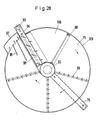
- some or all of the drainage surfaces are annular and consist of circular disks arranged one above the other, which are rotatably mounted about essentially vertical axes of rotation, that the upper circular disks are designed as pre-dewatering and intermediate pressure stages, so that the lower one Circular disc serves as a high pressure stage, and that a buffer or stacking container is provided at least between the medium pressure stage and the high pressure stage.
- the buffer or stacking container is arranged above the lower circular disc, and that the bottom of the stacking container is formed by the drainage surface belonging to the high-pressure zone, that the high-pressure stage is formed by a large number of juxtaposed ones is constructed radially extending segments, which are connected to the continuous pressure membrane, that each segment is assigned at least one high-pressure generator, that an upper and a lower, altogether annular pressure plate arrangement is provided, the distance between the two pressure plate arrangements being optionally changeable so that the lower pressure plate has a rotary disk provided with a rotary drive, and that each segment has an upper pressure plate and the upper pressure plate can be raised and lowered independently of the position of adjacent upper pressure plates.
- an overall circular drainage plate arrangement provided with drainage structures is arranged on the lower pressure plate arrangement, that an annular filter belt rests on the drainage plate arrangement, and that the drainage plate arrangement as an elastic plate, in particular as a rubber or plastic plate , is formed with vertical through openings and horizontal drainage channels.
- the plate is designed as a plastic grid with only vertical through openings.
- a particularly preferred embodiment with the circular filter surfaces can be created in that three superimposed circular disks with filter devices are provided, of which the top one forms a gravity drainage stage, the middle one forms a medium pressure stage designed as a vacuum stage and the bottom one forms the high pressure stage such that the top circular disks also form circular drainage plates are provided with vertical through openings, that the axes of rotation of the circular disks are laterally offset from one another, that the circular disks each have an outer circumferential, annular end face and can be driven by means of an engaging friction wheel drive, and that slides are provided at both ends of the high-pressure stage, which came the all-round closed mud always finish at their ends.
- This embodiment is preferred because the application of negative pressure is structurally easier to solve than the application of positive pressure if a filter surface moves on a circular path. Due to the lateral offset of the axes of rotation, the sludge can be transferred from one dewatering stage to the next in a particularly simple mechanical manner.
- the high-pressure generators are preferably designed as hydraulic pressure cylinders.
- the segments are formed by closed frames, the hydraulic pressure cylinders being supported on the one hand on the upper leg of the frame and on the other hand on the upper pressure plate, and that effective springs are provided between the upper leg and the upper pressure plate for lifting the pressure plate are.
- the pressure membrane is advantageous to design the pressure membrane as a circular segment-shaped component with sealing strips on the radial edges, the slides being arranged at the ends of the high-pressure zone defined by the circular ring segment.
- the movable pressure plates have a protruding central region transverse to the direction of movement of the sludge volume, essentially parallel to the filter surface, which merges on both sides into upwardly inclined regions that the Pressure membrane is attached to the central area, and that the central area is about half to four fifths of the total width of the printing plates.
- This special shape of the pressure plates leads to a particularly advantageous pressure curve across the width of the sludge chamber volume.
- the lower circular disc of the high pressure stage on sprung rollers on the un tere legs of the frame is stored.
- a structurally interesting modification of the device according to the invention can be created in that the gravity pre-dewatering stage and the vacuum medium pressure stage are round, while the high pressure stage is elongated with a horizontal circumferential filter belt.
- This embodiment is constructively interesting because the straight design of the high-pressure stage is simpler than the circular construction.
- the bottom of the buffer or stacking container is formed by a separately driven filter belt, that the gravity pre-dewatering stage and the vacuum medium pressure stage are arranged next to one another in one plane, that at least the wedge stage is provided with filtrate collecting troughs, and that the springs acting on the sealing strips of the pressure membrane are designed to be adjustable in their pressure force.
- This measure allows better control of the feed of the sludge into the high-pressure zone, advantageously reduces the overall height of the overall device, and the filtrate pressed out of the sludge can easily be led out laterally from the device.
- the circular embodiment of the device according to the invention can be further developed in that the upper circular disk consists half of a gravity drainage stage and half of a vacuum drainage stage, and that the devices for generating negative pressure are designed to rotate with the circular disk. In this way, one of the circular disks can be saved and the overall height of the overall device can be reduced.
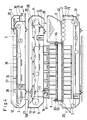
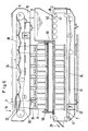
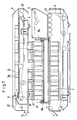
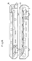
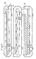
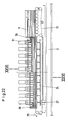
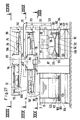
- FIGS. 1 to 3 according to the invention for dewatering of sludge and similar substances, schematically illustrated in FIGS. 1 to 3, comprises, according to the illustrated embodiment, a high-pressure stage 2, to which two pre-dewatering stages 3 and 4 are assigned.
- the pre-dewatering stages are a gravity dewatering stage 3 and a medium pressure stage 4 and after passing through the pre-dewatering stages 3 and 4, the sludge is fed into a closed sludge chamber volume 9 which moves past pressure plates 7,8 intermittently.
- the sludge chamber volume 9 is subjected to a high pressure between the stationary pressure plates 7, 8 and the resulting sludge cake 10 is discharged in the meantime.
- each of the dewatering stages 2 to 4 has its own circulating filter belt 17, 18, 19, which will be referred to below.
- the sludge After leaving a pretreatment device 21, the sludge is introduced via the sludge feed 14 into a mixing and reaction chamber 22, from where it reaches the pre-dewatering device 3.
- the pre-dewatering device 3 is designed as a gravity dewatering stage, the sludge being fed onto a continuously rotating filter belt 18 after leaving the mixing and reaction space.
- the filter belt 18 runs over drainage plates 24, which are preferably designed as plastic grids.
- Mud plows 26 are provided in the conveyor path of the essentially horizontal filter belt 18 of the gravity pre-dewatering stage 12, which serve to support the gravity dewatering process.
- the dewatering stage subsequent to the pre-dewatering stage 4 or 12 is designed as a medium pressure stage 13, in which the sludge is exposed to a medium pressure.
- a first buffer or stacking container 11A is provided between the sludge discharge 23 of the gravity pre-dewatering stage 12 and the actual medium pressure stage 13, the function of which is explained in more detail below.
- the bottom of the first buffer or stacking container 11A is formed by the continuously circulating filter belt 19 of the medium pressure stage 13, which is also formed in this area on drainage plates 24 in the form of plastic grids 25.
- the medium pressure stage 13 is designed as a wedge stage 15 in that a further circulating belt is provided, which is designed as a pressure belt 35.
- the pressure belt 35 forms, together with the rotating filter belt 18, a wedge space 36, in which the sludge 6 is exposed to a pressure which increases continuously in the conveying direction.
- the pressure band 35 is provided with box-shaped formations 37, which consist of continuous edge strips 38 and transverse webs 39 connecting them.
- the pressure belt 35 with the box-shaped formations 37 forms a first closed sludge chamber 40 of medium pressure, which is divided into individual chambers by the box-shaped formations 41.
- the overhead pressure belt 35 with the box-shaped formations 38, as illustrated, runs counterclockwise onto the filter belt 19, so that the sludge is conveyed in portions through the wedge chamber 36 and continuously increases as a closed volume exposed to pressure.
- the sludge 6 is transferred into a buffer or stacking container 11 which is interposed between the high pressure stage and the wedge stage.
- the continuously circulating filter belt 19 is supported on rollers 53 lying closely next to one another, the same rollers 53 lying closely next to one another supporting the pressure belt 35 on the opposite side of the wedge chamber 36.
- each of the dewatering stages 2 to 4 the associated filter belt 17, 18 and 19 is driven independently of the other filter belts, the filter belts 18, 19 being continuously driven at adjustable speeds in the pre-dewatering and medium pressure stages 3 and 4.
- the wedge space 36 between the pressure belt 35 and the filter belt 19 can be made adjustable by combining one of the two pumps consisting of the rollers 53 in a pivotable frame (not shown), whereby on the end of such a frame adjacent the first buffer or stacking container 11A may be pressurized.
- the high-pressure stage 2 adjoining the second buffer or stacking container likewise forms a sludge chamber which is closed on all sides.
- the high pressure stage 2 consists of a horizontal filter belt 17 which is driven intermittently in accordance with the pressure stroke of the high pressure stage 2.
- a pressure is above the horizontal filter belt 17 membrane 50 arranged with side sealing strips, the space thus formed between the filter belt 17 and the pressure membrane 50 is closed at the end faces by two slides 55, 56.
- the pressure membrane 50 is connected in a central region 52 to the movable pressure plates 8 of the high pressure stage 2.
- the slides 55, 56 are designed as flat slides.
- the lateral sealing strips 51 are prestressed on the pressure membrane 50 in the direction of the filter band 17 by springs 60, so that the sealing strips are in constant contact with the filter band 17.
- the springs are supported on the movable pressure plate 8 in such a way that the sealing stroke is simultaneously increased during the pressure stroke.
- the high pressure stage 8 consists of the pressure membrane 50 and the discontinuously intermittently circulating filter belt 17 from a number of stationary pressure plate pairs 7 and 8, each of which consists of a lower, fixedly mounted pressure plate 7 and an upper, the lower pressure plate 7 exactly opposite, in vertical Movable pressure plate 8 exists.
- Each pair of pressure plates 7, 8 is combined in a frame 58 which is formed by the lower pressure plate 7, two side supports 63 and a crosshead 64.
- Each of the frames 58 forms a segment 90, the high-pressure stage being built up from a desired number of such segments.
- a high-pressure generator 91 or 92 which is designed as a hydraulic cylinder, is fastened to the side, the one in the vertical direction toward un ten acting pistons 127, 128 cooperate with the upper pressure plate 8 to press them under high pressure in the direction of the lower pressure plate 7, as a result of which the trapped in the sludge chamber 45 of the high-pressure stage between the filter belt 17 and the pressure membrane 50 dewaters under steady high pressure becomes.
- the pressing forces that occur here are accommodated in the closed system of the frame 58 and are not transmitted to any foundations.
- each pressure plate 8 has an outwardly elongated arm 136, 137 on each side, between which and the opposite end of the lower stationary pressure plate 7 a compression spring 125 is clamped.
- the compression springs 125 cause the upper pressure plates 8 to lift off automatically from the lower pressure plates 7 after completion of the pressing process and after relieving the pressure from the high pressure generators 91, 92, and thus to enable the filter belt 17 with the sludge cake 10 located thereon to be advanced.
- additional spring-biased pressure rollers can be provided for guiding the filter belt, which are characterized by corresponding recesses in the drainage plate arrangement 24, i. H. in the plastic grid 25, and extend the filter belt 17 slightly after relieving the pressure on the upper pressure plates 8.
- the lateral sealing strips 51 of the pressure plate 50 are constantly in contact with the filter band 17 under the pressure of the springs 60, it is preferred to provide replaceable wear parts on the sealing strips 51, on their contact surface 61 with the filter band 17, for example are inserted into the sealing strips 51 in a kind of tongue and groove connection.
- the wearing parts 62 can preferably be low-friction plastic strips or the like.
- the pressure membrane 50 is designed as a continuous rubber cover 65.
- pressure sensors 68 are provided in the sludge chamber 45 of the high-pressure stage 2, which automatically switch the pressure increase as a function of the pressure prevailing in the sludge via a control device 69.
- the pressure is therefore increased automatically in accordance with the degree of drainage already achieved, which is much more precise than the previously used time switch.
- the pressure sensors consequently adapt the pressure to the dewatering behavior of the respective sludge via the control device.
- the movable pressure plates 8 have a protruding central region 130 transversely to the direction of movement of the sludge volume, which essentially extends parallel to the surface of the filter belt 17, which merges into obliquely upward regions 131, 132 on both sides.
- This configuration results in a particularly favorable pressure profile of the pressure exerted on the pressure membrane 50.
- the pressure membrane is attached to the central region 130.
- the middle region can be up to four fifths or more of the total width of the printing plates 8.
- the springs acting on the sealing strips 51 of the pressure diaphragm 50 can be designed to be adjustable in their pressure force, in order to increase the minimum sealing force during the relief stroke in the case of more closable sludges.
- the previously described device 1 works in the following way: From the pretreatment device 21, the type of sludge mixed with flocculants and other substances supporting dewatering first reaches the mixing and reaction chamber 22, from where it reaches the continuously circulating filter belt 18 of the gravity pre-dewatering stage 12 via a weir 48. In the essentially horizontal drainage section, the sludge 6 is occasionally turned by the sludge plows 26 and dewatered under gravity, the filtrate passing through the plastic grid 25 supporting the filter belt 18 down into a filtrate collecting trough 31 and being discharged laterally.
- the filter belt 18 runs around a deflection roller 44 back through a washing device 27, while the sludge 6 reaches the first buffer or stacking container 11A in front of the germ stage 15.
- the sludge is further dewatered in accordance with the rise in the sludge level in the container 11A under the effect of gravity, the filtrate being passed through the continuously circulating filter belt 19 of the wedge stage 15 and through the plastic grid 24 arranged below into the filtrate collecting trough assigned to the wedge stage 31 arrives.
- the sludge is conveyed and portioned into the wedge space 36 by the continuously rotating filter belt 19 and the rising pressure belt 35 dewatered there under the constantly increasing pressure as the closed sludge volume of the sludge chamber 40 of the medium pressure stage divided into individual chambers 41.
- the filter belt 19 runs around a deflection roller 59 back through a washing device 27, the sludge being transferred in largely dewatered form at the outlet 28 of the medium pressure stage 13 into the buffer or stacking container 11 pre-configured for the high pressure stage 2.
- the sludge is fed continuously from the medium pressure stage 13 into the buffer or stacking container 11 in accordance with the continuous mode of operation of the above-mentioned dewatering stages, while the sludge is withdrawn discontinuously from the buffer or stacking container 11 in accordance with the discontinuous, cyclical mode of operation of the high pressure stage.
- the bottom 42 of the buffer or stacking container 11 is formed by the filter belt 17 of the high-pressure stage 2, which is supported in the area of the bottom 42 on rollers arranged close to one another.
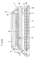
- the stacking device 11 is formed by at least one second high-pressure stage 2A.
- a switchover device 138 is provided in order to alternately fill the high-pressure stages 2, 2A.
- the high pressure stages 2 and 2A are alternately opened or closed in cycles and alternately carry out a press stroke. While one of the high pressure stages 2 or 2A is performing its press stroke, the other high pressure stage 2 or 2A is open and serves as a stacking device 11 for the high pressure stage performing the press stroke.
- the illustrated switching device 138 is designed as a pneumatically or electrically controlled deflection flap 139, which alternately connects the outlet 28 of the medium pressure stage 13 to one of the high pressure stages 2 or 2A via a chute 140 or the like, in each case with the high pressure stage that is currently open and does not exercise their press stroke.
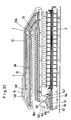
- the stacking device 11 is designed as a stacking belt 141, the stacking belt 141 being reversible in its drive direction.
- the stacking belt 141 runs to the right in the view according to FIG. 34 and picks up the sludge discharged from the outlet 28 of the medium pressure stage 13.
- the direction of rotation of the drive of the stacking belt 141 is reversed, so that the sludge thereon is fed into the high-pressure stage together with the sludge which continues to emerge from the medium-pressure stage 13.
- the direction of rotation of the drive of the stacking belt 141 is reversed again, so that this again acts as a buffer.
- the stacking device 11 is designed as a storage bunker 142 and, on the other hand, the pre-dewatering stage 3, as explained in more detail below, is designed as a double section.
- the illustrated storage bunker 142 which forms the stacking device 11, contains a portioning device 143, which alternately divides the sludge continuously fed from the medium pressure stage 13 into corresponding portions in the feed quantity for the high pressure stage 2.
- the portioning device 143 is designed as a control flap 144 which divides the storage bunker 142 into two chambers 146, 147.
- the chambers 146, 147 take up the sludge 6 alternately, wherein when the control flap 144 is switched over to form the other chamber, the previously taken up sludge portion releases for feeding into the high pressure stage 2.
- the control flap 144 is connected to a guide flap 145 which guides the sludge into the corresponding chamber 146 or 147.
- the preferred embodiment of the pre-dewatering stage 3 which is also shown schematically in FIG. 35, has two parallel gravity pre-dewatering stages 12, 12A, which are fed together via the sludge feeder 14.
- the two parallel gravity preliminary drainage stages 12, 12A arranged one above the other have their outputs 23, 23A together on the inlet side of the medium pressure stage 13.
- the sludge feeder 14 is designed in such a way that both gravity pre-dewatering stages 12 and 12A are fed with equal amounts of sludge via weirs 148, 149.
- the filter belts 18 and 18A of the gravity pre-drainage stages 12 and 12A are driven at the same speed.
- This embodiment offers the advantage if, in practice, the medium pressure stage 13 is designed in such a way that a layer height of 60 mm is reduced to 30 mm after passing through the medium pressure stage 13, each of the gravity pre-dewatering stages can also be loaded with a layer thickness of 60 mm, which is then reduced to two times 30 mm on a correspondingly larger area and therefore the Feed height for the medium pressure level corresponds.
Landscapes
- Chemical & Material Sciences (AREA)
- Chemical Kinetics & Catalysis (AREA)
- Engineering & Computer Science (AREA)
- Mechanical Engineering (AREA)
- Treatment Of Sludge (AREA)
Applications Claiming Priority (2)
| Application Number | Priority Date | Filing Date | Title |
|---|---|---|---|
| DE3914661 | 1989-05-03 | ||
| DE3914661A DE3914661C2 (de) | 1989-05-03 | 1989-05-03 | Vorrichtung zur Fest-Flüssig-Trennung |
Publications (2)
| Publication Number | Publication Date |
|---|---|
| EP0396079A2 true EP0396079A2 (fr) | 1990-11-07 |
| EP0396079A3 EP0396079A3 (fr) | 1992-03-11 |
Family
ID=6380042
Family Applications (1)
| Application Number | Title | Priority Date | Filing Date |
|---|---|---|---|
| EP19900108216 Withdrawn EP0396079A3 (fr) | 1989-05-03 | 1990-04-30 | Dispositif de déshydratation de boues et substances similaires |
Country Status (2)
| Country | Link |
|---|---|
| EP (1) | EP0396079A3 (fr) |
| DE (1) | DE3914661C2 (fr) |
Cited By (6)
| Publication number | Priority date | Publication date | Assignee | Title |
|---|---|---|---|---|
| EP0714687A3 (fr) * | 1994-12-01 | 1996-08-21 | Albert Baehr | Procédé et appareil de déshydratation de bones et autres |
| EP2703366A1 (fr) * | 2012-08-29 | 2014-03-05 | Albert Bähr | Dispositif de séparation solide-liquide de mélanges de matière et suspensions |
| CN106964188A (zh) * | 2017-03-30 | 2017-07-21 | 通山新知力环保设备机械厂(普通合伙) | 一种用于带式污泥压滤机的压滤方法 |
| EP2333032B1 (fr) | 2009-12-09 | 2018-07-25 | ENI S.p.A. | Methode pour la preparation d'une composition d'hydrocarbures capable comme carburant et combustible |
| CN114148018A (zh) * | 2021-12-20 | 2022-03-08 | 湖南大三湘茶油股份有限公司 | 螺旋榨油设备 |
| CN120253339A (zh) * | 2025-04-03 | 2025-07-04 | 江西维尔宝食品生物有限公司 | 基于生物传感器的食品油脂安全检测装置 |
Families Citing this family (3)
| Publication number | Priority date | Publication date | Assignee | Title |
|---|---|---|---|---|
| DE4219297A1 (de) * | 1992-06-12 | 1993-12-16 | Petkus Wutha Getreide Und Saat | Stau- und Durchmischungseinrichtung für eine Schlammentwässerungsanlage |
| DE19539484C2 (de) * | 1994-12-01 | 2001-03-08 | Albert Baehr | Verfahren und Vorrichtung zum Entwässern von Schlämmen und ähnlichen Substanzen |
| DE102008047427A1 (de) * | 2008-09-15 | 2010-04-15 | Bähr, Albert, Dipl.-Ing. | Verfahren und Vorrichtung zur Fest-Flüssig-Trennung von Stoffgemischen und Suspensionen |
Family Cites Families (7)
| Publication number | Priority date | Publication date | Assignee | Title |
|---|---|---|---|---|
| DE1080970B (de) * | 1954-01-05 | 1960-05-05 | Buckau Wolf Maschf R | Verfahren zur Druckentwaesserung von mit Torfstaub vorbehandeltem Rohtorf |
| FR1515344A (fr) * | 1966-03-05 | 1968-03-01 | Dispositif pour la séparation, par filtration sous pression, de liquides et de constituants solides | |
| SE397081B (sv) * | 1976-02-27 | 1977-10-17 | Kaelle Regulatorer Ab | Sett och anordning for avvattning av avloppsslam |
| FR2503578B1 (fr) * | 1981-04-13 | 1987-07-17 | Guinard Separation | Installation de filtration a coursiers passant entre des plateaux de serrage |
| DE3635766A1 (de) * | 1986-10-21 | 1988-04-28 | Albert Baehr | Vorrichtung zum entwaessern von schlamm und aehnlichen substanzen |
| DE3734974A1 (de) * | 1986-10-21 | 1989-04-20 | Baehr Albert | Vorrichtung zum entwaessern von schlamm und aehnlichen substanzen |
| DE3715829A1 (de) * | 1987-05-12 | 1988-12-01 | Baehr Albert | Kontinuierlich arbeitende hochdruck-filterpresse zum entwaessern von schlamm |
-
1989
- 1989-05-03 DE DE3914661A patent/DE3914661C2/de not_active Expired - Fee Related
-
1990
- 1990-04-30 EP EP19900108216 patent/EP0396079A3/fr not_active Withdrawn
Cited By (7)
| Publication number | Priority date | Publication date | Assignee | Title |
|---|---|---|---|---|
| EP0714687A3 (fr) * | 1994-12-01 | 1996-08-21 | Albert Baehr | Procédé et appareil de déshydratation de bones et autres |
| US5863429A (en) * | 1994-12-01 | 1999-01-26 | Baehr; Albert | Method and apparatus for removing water from sludge and similar substances |
| EP2333032B1 (fr) | 2009-12-09 | 2018-07-25 | ENI S.p.A. | Methode pour la preparation d'une composition d'hydrocarbures capable comme carburant et combustible |
| EP2703366A1 (fr) * | 2012-08-29 | 2014-03-05 | Albert Bähr | Dispositif de séparation solide-liquide de mélanges de matière et suspensions |
| CN106964188A (zh) * | 2017-03-30 | 2017-07-21 | 通山新知力环保设备机械厂(普通合伙) | 一种用于带式污泥压滤机的压滤方法 |
| CN114148018A (zh) * | 2021-12-20 | 2022-03-08 | 湖南大三湘茶油股份有限公司 | 螺旋榨油设备 |
| CN120253339A (zh) * | 2025-04-03 | 2025-07-04 | 江西维尔宝食品生物有限公司 | 基于生物传感器的食品油脂安全检测装置 |
Also Published As
| Publication number | Publication date |
|---|---|
| EP0396079A3 (fr) | 1992-03-11 |
| DE3914661A1 (de) | 1990-11-08 |
| DE3914661C2 (de) | 1998-04-23 |
Similar Documents
| Publication | Publication Date | Title |
|---|---|---|
| DE2917986C2 (de) | Stehende Filtriervorrichtung | |
| DE2844697C2 (de) | Filterpresse zum Entwässern von Schlamm und ähnlichen Substanzen | |
| DE69206096T2 (de) | Druckraumfilter für Flüssigkeiten. | |
| DE2343324A1 (de) | Filterpresse, insbesondere zur entwaesserung von schlamm in abwasserklaeranlagen | |
| EP0571581A1 (fr) | Presse a cylindres | |
| EP0397082B1 (fr) | Procédé et dispositif pour la déshydratation de boues et de produits analoques | |
| DE2439176A1 (de) | Vorrichtung zum kontinuierlichen trennen von feststoff/fluessigkeitsgemischen aller art | |
| EP0264899B1 (fr) | Dispositif de déshydratation de boues et de matières similaires | |
| DE3725528C2 (de) | Filterpresse | |
| EP0396079A2 (fr) | Dispositif de déshydratation de boues et substances similaires | |
| DE3410745A1 (de) | Doppelbandpresse | |
| EP0013548B1 (fr) | Dispositif pour la déshydratation de matières contenant de l'eau | |
| DE472419C (de) | Presse aus zwei endlosen, keilfoermig gegeneinanderlaufenden Baendern | |
| DE2510010A1 (de) | Verfahren und vorrichtung zum entwaessern von schlamm oder aehnlichen substanzen, insbesondere von in abwasserklaeranlagen oder dergleichen anfallendem schlamm durch filtration | |
| DE10207451A1 (de) | Vorrichtung und Verfahren zur Entwässerung von Schlämmen | |
| AT391297B (de) | Ringwalzenpresse | |
| DE1964950A1 (de) | Bandfilter zum Entwaessern von Suspensionen,insbesondere von bei der Abwasseraufbereitung anfallendem Klaerschlamm | |
| DE4011776C2 (de) | Verfahren und Kammerfilterpresse zum Entwässern von Schlämmen und ähnlichen Substanzen | |
| WO2018172346A1 (fr) | Séparateur à approvisionnement par poutre de levage | |
| DE2635010C2 (de) | Presse zum Trocknen nasser Felle mit endlosen, seitlich abnehmbaren Filzbändern | |
| DE4223022A1 (de) | Vorrichtung zum Entwässern von Schlamm und ähnlichen Substanzen | |
| DE4012920C2 (de) | Vorrichtung zum Nachpressen von Rübenschnitzeln | |
| DE2823409A1 (de) | Siebbandpresse zur entwaesserung von schlaemmen | |
| AT85822B (de) | Vorrichtung zum Entwässern von Stoffbahnen. | |
| WO1991017041A1 (fr) | Presse a tamis sans fin |
Legal Events
| Date | Code | Title | Description |
|---|---|---|---|
| PUAI | Public reference made under article 153(3) epc to a published international application that has entered the european phase |
Free format text: ORIGINAL CODE: 0009012 |
|
| AK | Designated contracting states |
Kind code of ref document: A2 Designated state(s): AT CH FR GB IT LI NL |
|
| PUAL | Search report despatched |
Free format text: ORIGINAL CODE: 0009013 |
|
| AK | Designated contracting states |
Kind code of ref document: A3 Designated state(s): AT CH FR GB IT LI NL |
|
| STAA | Information on the status of an ep patent application or granted ep patent |
Free format text: STATUS: THE APPLICATION IS DEEMED TO BE WITHDRAWN |
|
| 18D | Application deemed to be withdrawn |
Effective date: 19920912 |