EP0396314A2 - Elastomerstreifen und Verfahren zu dessen Herstellung - Google Patents
Elastomerstreifen und Verfahren zu dessen Herstellung Download PDFInfo
- Publication number
- EP0396314A2 EP0396314A2 EP90304455A EP90304455A EP0396314A2 EP 0396314 A2 EP0396314 A2 EP 0396314A2 EP 90304455 A EP90304455 A EP 90304455A EP 90304455 A EP90304455 A EP 90304455A EP 0396314 A2 EP0396314 A2 EP 0396314A2
- Authority
- EP
- European Patent Office
- Prior art keywords
- support frame
- longitudinally
- strip
- elastomeric
- spaced
- Prior art date
- Legal status (The legal status is an assumption and is not a legal conclusion. Google has not performed a legal analysis and makes no representation as to the accuracy of the status listed.)
- Granted
Links
Images

Classifications
-
- E—FIXED CONSTRUCTIONS
- E06—DOORS, WINDOWS, SHUTTERS, OR ROLLER BLINDS IN GENERAL; LADDERS
- E06B—FIXED OR MOVABLE CLOSURES FOR OPENINGS IN BUILDINGS, VEHICLES, FENCES OR LIKE ENCLOSURES IN GENERAL, e.g. DOORS, WINDOWS, BLINDS, GATES
- E06B7/00—Special arrangements or measures in connection with doors or windows
- E06B7/16—Sealing arrangements on wings or parts co-operating with the wings
-
- B—PERFORMING OPERATIONS; TRANSPORTING
- B60—VEHICLES IN GENERAL
- B60J—WINDOWS, WINDSCREENS, NON-FIXED ROOFS, DOORS, OR SIMILAR DEVICES FOR VEHICLES; REMOVABLE EXTERNAL PROTECTIVE COVERINGS SPECIALLY ADAPTED FOR VEHICLES
- B60J10/00—Sealing arrangements
- B60J10/30—Sealing arrangements characterised by the fastening means
- B60J10/32—Sealing arrangements characterised by the fastening means using integral U-shaped retainers
-
- B—PERFORMING OPERATIONS; TRANSPORTING
- B29—WORKING OF PLASTICS; WORKING OF SUBSTANCES IN A PLASTIC STATE IN GENERAL
- B29C—SHAPING OR JOINING OF PLASTICS; SHAPING OF MATERIAL IN A PLASTIC STATE, NOT OTHERWISE PROVIDED FOR; AFTER-TREATMENT OF THE SHAPED PRODUCTS, e.g. REPAIRING
- B29C48/00—Extrusion moulding, i.e. expressing the moulding material through a die or nozzle which imparts the desired form; Apparatus therefor
- B29C48/03—Extrusion moulding, i.e. expressing the moulding material through a die or nozzle which imparts the desired form; Apparatus therefor characterised by the shape of the extruded material at extrusion
- B29C48/09—Articles with cross-sections having partially or fully enclosed cavities, e.g. pipes or channels
-
- B—PERFORMING OPERATIONS; TRANSPORTING
- B29—WORKING OF PLASTICS; WORKING OF SUBSTANCES IN A PLASTIC STATE IN GENERAL
- B29C—SHAPING OR JOINING OF PLASTICS; SHAPING OF MATERIAL IN A PLASTIC STATE, NOT OTHERWISE PROVIDED FOR; AFTER-TREATMENT OF THE SHAPED PRODUCTS, e.g. REPAIRING
- B29C48/00—Extrusion moulding, i.e. expressing the moulding material through a die or nozzle which imparts the desired form; Apparatus therefor
- B29C48/15—Extrusion moulding, i.e. expressing the moulding material through a die or nozzle which imparts the desired form; Apparatus therefor incorporating preformed parts or layers, e.g. extrusion moulding around inserts
- B29C48/154—Coating solid articles, i.e. non-hollow articles
-
- B—PERFORMING OPERATIONS; TRANSPORTING
- B60—VEHICLES IN GENERAL
- B60J—WINDOWS, WINDSCREENS, NON-FIXED ROOFS, DOORS, OR SIMILAR DEVICES FOR VEHICLES; REMOVABLE EXTERNAL PROTECTIVE COVERINGS SPECIALLY ADAPTED FOR VEHICLES
- B60J10/00—Sealing arrangements
- B60J10/15—Sealing arrangements characterised by the material
- B60J10/18—Sealing arrangements characterised by the material provided with reinforcements or inserts
-
- B—PERFORMING OPERATIONS; TRANSPORTING
- B60—VEHICLES IN GENERAL
- B60J—WINDOWS, WINDSCREENS, NON-FIXED ROOFS, DOORS, OR SIMILAR DEVICES FOR VEHICLES; REMOVABLE EXTERNAL PROTECTIVE COVERINGS SPECIALLY ADAPTED FOR VEHICLES
- B60J10/00—Sealing arrangements
- B60J10/20—Sealing arrangements characterised by the shape
- B60J10/21—Sealing arrangements characterised by the shape having corner parts or bends
-
- B—PERFORMING OPERATIONS; TRANSPORTING
- B60—VEHICLES IN GENERAL
- B60J—WINDOWS, WINDSCREENS, NON-FIXED ROOFS, DOORS, OR SIMILAR DEVICES FOR VEHICLES; REMOVABLE EXTERNAL PROTECTIVE COVERINGS SPECIALLY ADAPTED FOR VEHICLES
- B60J10/00—Sealing arrangements
- B60J10/20—Sealing arrangements characterised by the shape
- B60J10/24—Sealing arrangements characterised by the shape having tubular parts
-
- Y—GENERAL TAGGING OF NEW TECHNOLOGICAL DEVELOPMENTS; GENERAL TAGGING OF CROSS-SECTIONAL TECHNOLOGIES SPANNING OVER SEVERAL SECTIONS OF THE IPC; TECHNICAL SUBJECTS COVERED BY FORMER USPC CROSS-REFERENCE ART COLLECTIONS [XRACs] AND DIGESTS
- Y10—TECHNICAL SUBJECTS COVERED BY FORMER USPC
- Y10T—TECHNICAL SUBJECTS COVERED BY FORMER US CLASSIFICATION
- Y10T428/00—Stock material or miscellaneous articles
- Y10T428/24—Structurally defined web or sheet [e.g., overall dimension, etc.]
- Y10T428/2419—Fold at edge
- Y10T428/24198—Channel-shaped edge component [e.g., binding, etc.]
-
- Y—GENERAL TAGGING OF NEW TECHNOLOGICAL DEVELOPMENTS; GENERAL TAGGING OF CROSS-SECTIONAL TECHNOLOGIES SPANNING OVER SEVERAL SECTIONS OF THE IPC; TECHNICAL SUBJECTS COVERED BY FORMER USPC CROSS-REFERENCE ART COLLECTIONS [XRACs] AND DIGESTS
- Y10—TECHNICAL SUBJECTS COVERED BY FORMER USPC
- Y10T—TECHNICAL SUBJECTS COVERED BY FORMER US CLASSIFICATION
- Y10T428/00—Stock material or miscellaneous articles
- Y10T428/29—Coated or structually defined flake, particle, cell, strand, strand portion, rod, filament, macroscopic fiber or mass thereof
- Y10T428/2902—Channel shape
Definitions
- the invention relates to an elastomeric strip, preferably of the channel-shaped type, for sealing and/or decorative purposes, such as, for example, gripping and covering edge flanges on the periphery of a vehicle door, a door opening or the like. More particularly, the invention relates to an improved elastomeric strip and method of manufacture in which the strip is provided with longitudinally-spaced degraded regions, corresponding to the longitudinally-spaced curved sections of the flange, whereby the degraded regions of the elastomeric strip can faithfully follow the curved sections of the flange when the strip is mounted thereon.
- U.S. Patent No. 4,343,845 which issued to Burden et al on August 10, 1982, discloses (see Fig. 1A) an elastomeric strip 1 and method of manufacturing the same, in which the elastomeric strip 1 had a selected lateral region 2 along the length thereof reinforced with degradable material 4 and at least one other lateral region 3 reinforced with material that is non-degradable. Accordingly, when the weatherstrip is subjected to degredation conditions, the degradable material 4 in the selected region 2 is degraded and the non-degradable material 5 is in the other region 3 is not degraded.
- the degraded material breaks when the strip is flexed, so that longitudinal displacement of the selected region of the frame portion is no longer inhibited, resulting in an elastomeric strip of improved flexibility.
- the longitudinal displacement of the other region 3 is maintained for preventing undue elongation or stretching of the strip.
- selected laterally spaced apart regions 2, 3 of the displaceable frame portions of the strip such as the central and/or outer regions or portions thereof are reinforced with a degradable and a non-degradable material respectively.
- the entire weather strip is subjected to a degrading environment and only the degradable material is selectively degraded resulting in increased flexibility of the strip, allowing it to faithfully accommodate inside, outside, and lateral curves, or combinations thereof.
- limited elongation of the strip is achieved due to the presence of non-degraded material.
- Japanese Patent Application No. 75627/78 shows a channel-shaped elastomeric strip having a ladder-like frame having a plurality of parallel, spaced-apart metal rungs joined together by thin webs.
- a strip degrading apparatus comprising a power source is disclosed having prongs insertable through the strip coating and into contact with a pair of adjacent metal rungs for applying electrical current thereto. This causes the thin web between the two metal rungs to melt, allowing elongation of the strip to occur in this region.
- an elastomeric strip of substantially U-shaped cross-section and of a finite length for mounting on a flange having longitudinally-spaced curved sections.
- the finite length of elastomeric strip is provided with a plurality of longitudinally-spaced degraded regions corresponding to the longitudinally-spaced curved sections of the flange. Accordingly, all a manufacturer has to do upon receipt of the elastomeric strip of finite length is to mount it on a flange with the degraded regions accurately and faithfully following the curved sections of the flange.
- a method of manufacturing the elastomeric strip of finite length involves continuously advancing a reinforced wire support frame through an extrusion die, and then intermittently advancing the elastomeric strip through spaced heat applicators.
- the heat from the heat applicators effectively degrades the longitudinally-spaced regions of the degradable reinforcing material of the strip corresponding to the longitudinally-spaced curved sections of a flange.
- the elastomeric strip is continuously advanced in synchronism with the spaced heat applicators for degrading longitudinally-spaced regions of the degradable reinforcing material of the strip corresponding to the longitudinally-spaced curved sections of the flange.
- a door opening 10 is disclosed in a vehicle body 12 having a flange 14 along the outer periphery of the opening, onto which an elastomeric strip 16 of finite length is mounted.
- the flange 14 has a plurality of curved sections B, C, D, E, F, G and H.
- An object of this invention is to provide an elastomeric strip of finite length for completely covering flange 14 without any leakage gap between ends 18, 20 of the elastomeric strip, or at the curved sections B-H of flange 14.
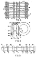
- a known type of wire support frame 22 is disclosed that is coated by any suitable elastomeric or polymeric material 26 to form strip 16.
- the frame 22 may be coated on at least one surface with one material, or with separate materials of differing hardness.
- the elastomeric strip 16, which is exemplary only, further has flange gripping fins 28, a sealing lip 30, and a bulb 32.
- the invention can be embodied in any other form of strip, such as an edge protector trim strip, or a glazing strip, for example, not shown, where a support frame 22 is used and increased flexibility of the elastomeric strip at curved sections is desired without undue elongation or stretching of the remainder of the strip.
- the support frame 22 preferably comprises a wire 34 arranged in a serpentine or zig zag path to provide looped portions 36 that are longitudinally displaceable prior to coating.
- Frame 22 could comprise any other suitable material and form, such as a ladder-like structure, for example, not shown.
- the frame portions are maintained in spaced relation with one another by a reinforcing material, such as by interweaving, knitting or knotting with them a plurality of strands 38 of material that will not break down during the manufacture of the elastomeric strip.
- Such strands 38 are preferably interwoven adjacent the looped portions 36 at the edge regions of the frame, and a plurality of such strands are interwoven through the central region of the frame.
- Such strands are selected to have a melting temperature such that they retain their reinforcing strength during at least the coating step of manufacturing the elastomeric strip. However, when the strip is subjected to a temperature higher than the coating process temperature, the strands 38 are melted or degraded. When the finished elastomeric strip is flexed during installation on a flange or the like, the degraded material breaks or gives allowing increased flexbility of the strip.
- a degrading station at which longitudinally-spaced regions B, C′, D′, E′, F′, G′, and H′ of the degradable reinforcing material of the elastomeric strip corresponding to the longitudinally-spaced curved sections B, C, D, E, F, G, and H respectively of the flange are degraded.
- a plurality of heat applicators, such as induction coils 40, for example are fixedly mounted in spaced relation with the spacing therebetween established to conform to the space between longitudinally-spaced curved sections B-H of flange 14.
- a cutting mechanism 42 is provided spaced from the degraded region H′ of the elastomeric strip a distance equal to the distance between the end surface of strip end 18 and the degraded region H′ shown in Fig. 1.
- the formed elastomeric strip 16 is continuously fed into any suitable strip accumulator, not shown, and the strip fed intermittently therefrom by hand or automatically by a conveyor, not shown, or the like into and through the degrading station.
- the leading end of elastomeric strip 16 is properly positioned at a fixed stop position by any suitable mechanical or optical sensing mechanism 44.
- the induction coils 40 are energized and remain coupled with the strip 16 for a predetermined time to degrade the longitudinally-spaced regions B′-H′ of the degradable reinforcing material 38 of the strip.
- cutting mechanism 42 Upon actuation of cutting mechanism 42, an elastomeric strip of finite length is severed from strip 16, and the operation is repeated.
- elastomeric strip 16 could be continuously fed from the strip accumulator through the degrading station, and spaced heat applicators mounted on a reciprocally movable or endless track, not shown, for transporting the heat applicators in synchronism with the longitudinally-spaced regions B′-H′ of the elastomeric strip to be degraded.
- strip 16 could be transported through a single degrading mechanism that is selectively energized synchronously with the selected regions B′-H′ of the strip as they pass the degrading mechanism for degrading such regions.
- the elastomeric strips of finite length exiting from the degrading station are collected and supplied to manufacturers for application to endless flanges 14 surrounding door opening 10 or the like.
- the strip ends 18, 20 are bonded to form a loop.
- one or both ends 18, 20 of strip 16 is applied to flange 14 at a point intermediate the curved sections B and H, and the strip mounted on the flange with the lontigudinally-spaced degraded regions B′-H′ thereof conforming or corresponding to the longitudinally-spaced curved sections B-H respectively.
Landscapes
- Engineering & Computer Science (AREA)
- Mechanical Engineering (AREA)
- Civil Engineering (AREA)
- Structural Engineering (AREA)
- Extrusion Moulding Of Plastics Or The Like (AREA)
- Seal Device For Vehicle (AREA)
- Laminated Bodies (AREA)
Applications Claiming Priority (2)
| Application Number | Priority Date | Filing Date | Title |
|---|---|---|---|
| US07/345,612 US5009947A (en) | 1989-04-28 | 1989-04-28 | Elastomeric strip and method of manufacture |
| US345612 | 1989-04-28 |
Publications (3)
| Publication Number | Publication Date |
|---|---|
| EP0396314A2 true EP0396314A2 (de) | 1990-11-07 |
| EP0396314A3 EP0396314A3 (de) | 1991-11-27 |
| EP0396314B1 EP0396314B1 (de) | 1995-11-22 |
Family
ID=23355732
Family Applications (1)
| Application Number | Title | Priority Date | Filing Date |
|---|---|---|---|
| EP90304455A Expired - Lifetime EP0396314B1 (de) | 1989-04-28 | 1990-04-25 | Elastomerstreifen und Verfahren zu dessen Herstellung |
Country Status (9)
| Country | Link |
|---|---|
| US (1) | US5009947A (de) |
| EP (1) | EP0396314B1 (de) |
| JP (1) | JP2542104B2 (de) |
| KR (1) | KR970011949B1 (de) |
| AT (1) | ATE130547T1 (de) |
| AU (1) | AU619401B2 (de) |
| CA (1) | CA1332547C (de) |
| DE (1) | DE69023690T2 (de) |
| IE (1) | IE71650B1 (de) |
Cited By (1)
| Publication number | Priority date | Publication date | Assignee | Title |
|---|---|---|---|---|
| FR2709451A1 (fr) * | 1993-09-03 | 1995-03-10 | Mesnel Sa Ets | Procédé pour le traitement d'un profilé d'étanchéité, notamment pour encadrements de portes de véhicules automobiles, et profilé obtenu par ce traitement. |
Families Citing this family (24)
| Publication number | Priority date | Publication date | Assignee | Title |
|---|---|---|---|---|
| US5143666A (en) * | 1989-04-28 | 1992-09-01 | Schlegel Corporation | Method for manufacturing an improved elastomeric strip |
| DE4027191A1 (de) * | 1990-08-28 | 1992-03-05 | Metzeler Automotive Profiles | Verfahren zur herstellung eines dichtungsprofils und nach dem verfahren hergestelltes dichtungsprofil |
| JP2808911B2 (ja) * | 1991-03-05 | 1998-10-08 | 豊田合成株式会社 | 自動車用ウエザストリップ |
| EP0586073B1 (de) * | 1992-07-31 | 1997-03-26 | Tokai Kogyo Kabushiki Kaisha | Extrudierte Hohlprofile and Herstellungsverfahren |
| DE4302662C2 (de) * | 1993-01-30 | 1994-11-03 | Raymond A Gmbh & Co Kg | Halteelement zum vertikalen Fixieren einer in einem Fensterrahmen eines Kraftfahrzeuges einklebbaren Glasscheibe |
| DE4331790C2 (de) * | 1993-09-18 | 1996-02-08 | Daimler Benz Aerospace Ag | Einrichtung zur Vermeidung von Quietschgeräuschen durch eine Dichtung an einer Fensterscheibe |
| DE4446450C1 (de) * | 1994-12-23 | 1996-04-04 | Johnson Controls Gmbh & Co Kg | Befestigungselement zum Einschäumen in ein Schaumteil |
| US6023888A (en) * | 1996-09-25 | 2000-02-15 | Schlegel Corporation | Door and window channel seal |
| US6214267B1 (en) | 1998-05-07 | 2001-04-10 | The Standard Products Company | Extrusion with variable neutral axis wire core |
| JP4015341B2 (ja) * | 2000-03-02 | 2007-11-28 | 平 佐藤 | ベッド用蒲団脱落防止兼昇降補助装置 |
| US6461713B2 (en) | 2000-12-18 | 2002-10-08 | Schlegel Corporation | Carrier with set down elongation reducing member |
| US6732648B1 (en) * | 2003-05-05 | 2004-05-11 | Day International Inc. | Printing blanket sleeve having sound dampening feature |
| US20060177627A1 (en) * | 2005-02-09 | 2006-08-10 | Schlegel Corporation | Carrier assembly with fused power and frame-warp aperture |
| US7718251B2 (en) | 2006-03-10 | 2010-05-18 | Amesbury Group, Inc. | Systems and methods for manufacturing reinforced weatherstrip |
| JP4771533B2 (ja) * | 2006-03-16 | 2011-09-14 | パラマウントベッド株式会社 | 仰臥台における側柵の支持機構 |
| JP4920558B2 (ja) * | 2007-11-13 | 2012-04-18 | パラマウントベッド株式会社 | 病院搬送用ストレッチャー等の柵及びそのロック機構 |
| US20090243142A1 (en) * | 2008-03-26 | 2009-10-01 | Jyco Sealing Technologies, Inc. | Coextruded polymer molding having selectively notched carrier |
| US9580954B2 (en) | 2009-10-05 | 2017-02-28 | R Value, Inc. | Press fit storm window system |
| US10202796B2 (en) | 2009-10-05 | 2019-02-12 | R Value, Inc. | Press fit storm window system |
| US9255438B2 (en) | 2009-10-05 | 2016-02-09 | R Value, Inc. | Press fit storm window system |
| JP5342581B2 (ja) * | 2011-03-01 | 2013-11-13 | 西川ゴム工業株式会社 | 自動車用オープニングシール及びその製造方法 |
| FR2982191A1 (fr) * | 2011-11-09 | 2013-05-10 | Cooper Standard Automotive France S A | Procede de fabrication d'un joint avec modification locale du profil par induction |
| CN107923217A (zh) | 2015-02-13 | 2018-04-17 | 埃美斯博瑞集团有限公司 | 低压缩力的tpe耐候性密封件 |
| EP3728779B1 (de) * | 2017-12-22 | 2023-09-06 | Raxit Seals ApS | Verstärkte flexible struktur oder dichtung |
Family Cites Families (15)
| Publication number | Priority date | Publication date | Assignee | Title |
|---|---|---|---|---|
| US3091821A (en) * | 1960-03-30 | 1963-06-04 | Schlegel Mfg Co | Beading for finishing structural edges |
| US3198689A (en) * | 1962-01-29 | 1965-08-03 | Schlegel Mfg Co | Garnishing bead |
| DE1478142C3 (de) * | 1965-06-04 | 1974-08-29 | Hannes 8100 Garmisch-Partenkirchen Marker | Vorderbacken für eine Sicherheits-Skibindung |
| GB1535715A (en) * | 1974-11-20 | 1978-12-13 | Draftex Dev Ag | Flexible sealing strips |
| JPS5375627A (en) * | 1976-12-17 | 1978-07-05 | Toyoda Gosei Kk | Method of formation for fitting trim |
| GB2026579B (en) * | 1978-07-29 | 1982-10-27 | Draftex Dev Ag | Channel-shaped sealing strips |
| US4343845A (en) * | 1980-07-30 | 1982-08-10 | Schlegel Corporation | Elastomeric strip and method of manufacturing same |
| US4413033A (en) * | 1982-06-07 | 1983-11-01 | Schlegel Corporation | Wire carrier and edge protector trim strip formed therefrom |
| DE3333474C2 (de) * | 1982-10-02 | 1996-05-02 | Draftex Ind Ltd | Kanalförmiger Dicht- oder Abschlußstreifen |
| US4464218A (en) * | 1983-04-18 | 1984-08-07 | Flex-O-Lators, Inc. | Method for reinforcing net materials |
| US4517233A (en) * | 1984-03-16 | 1985-05-14 | Schlegel Corporation | Two-wire carrier edge protector trim strip |
| US4624093A (en) * | 1984-04-12 | 1986-11-25 | Schlegel Corporation | Single-wire carrier edge protector trim strip |
| JPS6333453A (ja) * | 1986-07-28 | 1988-02-13 | Nippon Zeon Co Ltd | 熱可塑性ゴム組成物 |
| JPH01195032A (ja) * | 1988-01-29 | 1989-08-04 | Hashimoto Forming Ind Co Ltd | ウインドウモールディングの製造方法 |
| GB8827180D0 (en) * | 1988-11-21 | 1988-12-29 | Schlegel Uk Holdings | Composite extrusion |
-
1989
- 1989-04-28 US US07/345,612 patent/US5009947A/en not_active Expired - Lifetime
- 1989-09-26 CA CA000613240A patent/CA1332547C/en not_active Expired - Fee Related
-
1990
- 1990-04-05 IE IE123590A patent/IE71650B1/en not_active IP Right Cessation
- 1990-04-25 DE DE69023690T patent/DE69023690T2/de not_active Expired - Fee Related
- 1990-04-25 EP EP90304455A patent/EP0396314B1/de not_active Expired - Lifetime
- 1990-04-25 AT AT90304455T patent/ATE130547T1/de not_active IP Right Cessation
- 1990-04-26 JP JP2108999A patent/JP2542104B2/ja not_active Expired - Fee Related
- 1990-04-26 AU AU53976/90A patent/AU619401B2/en not_active Ceased
- 1990-04-27 KR KR1019900005944A patent/KR970011949B1/ko not_active Expired - Fee Related
Cited By (1)
| Publication number | Priority date | Publication date | Assignee | Title |
|---|---|---|---|---|
| FR2709451A1 (fr) * | 1993-09-03 | 1995-03-10 | Mesnel Sa Ets | Procédé pour le traitement d'un profilé d'étanchéité, notamment pour encadrements de portes de véhicules automobiles, et profilé obtenu par ce traitement. |
Also Published As
| Publication number | Publication date |
|---|---|
| DE69023690T2 (de) | 1996-05-09 |
| CA1332547C (en) | 1994-10-18 |
| JP2542104B2 (ja) | 1996-10-09 |
| JPH0367624A (ja) | 1991-03-22 |
| AU5397690A (en) | 1990-11-01 |
| IE901235A1 (en) | 1991-01-16 |
| EP0396314B1 (de) | 1995-11-22 |
| EP0396314A3 (de) | 1991-11-27 |
| KR900015965A (ko) | 1990-11-12 |
| KR970011949B1 (ko) | 1997-08-08 |
| DE69023690D1 (de) | 1996-01-04 |
| AU619401B2 (en) | 1992-01-23 |
| ATE130547T1 (de) | 1995-12-15 |
| US5009947A (en) | 1991-04-23 |
| IE71650B1 (en) | 1997-02-26 |
| IE901235L (en) | 1990-10-28 |
Similar Documents
| Publication | Publication Date | Title |
|---|---|---|
| US5009947A (en) | Elastomeric strip and method of manufacture | |
| US5143666A (en) | Method for manufacturing an improved elastomeric strip | |
| EP0045176B1 (de) | Elastischer Profilstreifen und Verfahren zu dessen Herstellung | |
| EP0096533B1 (de) | Drahtträger und daraus geformter Kantenschutzstreifen | |
| EP0062721B1 (de) | Elektrisch stromführender flexibler Schlauch | |
| EP0159136B1 (de) | Kantenschutzprofilträger | |
| EP0155811B1 (de) | Kantenschutzprofilträger mit Doppeldrahtgerüst | |
| CA2143507A1 (en) | Method of Forming Strip Products from Thermoplastic Materials | |
| US6214267B1 (en) | Extrusion with variable neutral axis wire core | |
| US20040109965A1 (en) | Protective sleeving and manufacturing process for producing this type of sleeving | |
| EP0408291B1 (de) | Verfahren zur Herstellung eines elastomeren Streifens | |
| US3436891A (en) | Rubber moldings for automobile windows and manufacture thereof | |
| EP0922598A1 (de) | Dichtungs- und/oder Verkleidungselemente | |
| JPS61229636A (ja) | 自動車用ウエザストリツプおよびその製造方法 | |
| GB2333796A (en) | Sealing strip having soft extruded material covering support member and fixing means | |
| EP0995622B1 (de) | Verstärkungskerne- oder Einlagen für biegsame Erzeugnisse | |
| GB2063975A (en) | Strip Structures for Trimming and Sealing | |
| JP3015025B1 (ja) | トリム用インサ―ト及びトリム | |
| JPH09240387A (ja) | 補強芯材の接続構造 |
Legal Events
| Date | Code | Title | Description |
|---|---|---|---|
| PUAI | Public reference made under article 153(3) epc to a published international application that has entered the european phase |
Free format text: ORIGINAL CODE: 0009012 |
|
| AK | Designated contracting states |
Kind code of ref document: A2 Designated state(s): AT BE CH DE DK ES FR GB GR IT LI LU NL SE |
|
| PUAL | Search report despatched |
Free format text: ORIGINAL CODE: 0009013 |
|
| AK | Designated contracting states |
Kind code of ref document: A3 Designated state(s): AT BE CH DE DK ES FR GB GR IT LI LU NL SE |
|
| 17P | Request for examination filed |
Effective date: 19920430 |
|
| 17Q | First examination report despatched |
Effective date: 19931210 |
|
| GRAA | (expected) grant |
Free format text: ORIGINAL CODE: 0009210 |
|
| AK | Designated contracting states |
Kind code of ref document: B1 Designated state(s): AT BE CH DE DK ES FR GB GR IT LI LU NL SE |
|
| PG25 | Lapsed in a contracting state [announced via postgrant information from national office to epo] |
Ref country code: DK Effective date: 19951122 Ref country code: CH Effective date: 19951122 Ref country code: AT Effective date: 19951122 Ref country code: IT Free format text: LAPSE BECAUSE OF FAILURE TO SUBMIT A TRANSLATION OF THE DESCRIPTION OR TO PAY THE FEE WITHIN THE PRE;WARNING: LAPSES OF ITALIAN PATENTS WITH EFFECTIVE DATE BEFORE 2007 MAY HAVE OCCURRED AT ANY TIME BEFORE 2007. THE CORRECT EFFECTIVE DATE MAY BE DIFFERENT FROM THE ONE RECORDED.SCRIBED TIME-LIMIT Effective date: 19951122 Ref country code: ES Free format text: THE PATENT HAS BEEN ANNULLED BY A DECISION OF A NATIONAL AUTHORITY Effective date: 19951122 Ref country code: BE Effective date: 19951122 Ref country code: NL Free format text: LAPSE BECAUSE OF FAILURE TO SUBMIT A TRANSLATION OF THE DESCRIPTION OR TO PAY THE FEE WITHIN THE PRESCRIBED TIME-LIMIT Effective date: 19951122 Ref country code: GR Free format text: LAPSE BECAUSE OF FAILURE TO SUBMIT A TRANSLATION OF THE DESCRIPTION OR TO PAY THE FEE WITHIN THE PRESCRIBED TIME-LIMIT Effective date: 19951122 Ref country code: LI Effective date: 19951122 |
|
| REF | Corresponds to: |
Ref document number: 130547 Country of ref document: AT Date of ref document: 19951215 Kind code of ref document: T |
|
| REF | Corresponds to: |
Ref document number: 69023690 Country of ref document: DE Date of ref document: 19960104 |
|
| ET | Fr: translation filed | ||
| PG25 | Lapsed in a contracting state [announced via postgrant information from national office to epo] |
Ref country code: SE Effective date: 19960222 |
|
| PG25 | Lapsed in a contracting state [announced via postgrant information from national office to epo] |
Ref country code: LU Free format text: LAPSE BECAUSE OF NON-PAYMENT OF DUE FEES Effective date: 19960430 |
|
| NLV1 | Nl: lapsed or annulled due to failure to fulfill the requirements of art. 29p and 29m of the patents act | ||
| REG | Reference to a national code |
Ref country code: CH Ref legal event code: PL |
|
| PLBE | No opposition filed within time limit |
Free format text: ORIGINAL CODE: 0009261 |
|
| STAA | Information on the status of an ep patent application or granted ep patent |
Free format text: STATUS: NO OPPOSITION FILED WITHIN TIME LIMIT |
|
| 26N | No opposition filed | ||
| REG | Reference to a national code |
Ref country code: GB Ref legal event code: IF02 |
|
| PGFP | Annual fee paid to national office [announced via postgrant information from national office to epo] |
Ref country code: FR Payment date: 20050408 Year of fee payment: 16 |
|
| PGFP | Annual fee paid to national office [announced via postgrant information from national office to epo] |
Ref country code: GB Payment date: 20050420 Year of fee payment: 16 |
|
| PGFP | Annual fee paid to national office [announced via postgrant information from national office to epo] |
Ref country code: DE Payment date: 20050421 Year of fee payment: 16 |
|
| PG25 | Lapsed in a contracting state [announced via postgrant information from national office to epo] |
Ref country code: GB Free format text: LAPSE BECAUSE OF NON-PAYMENT OF DUE FEES Effective date: 20060425 |
|
| PG25 | Lapsed in a contracting state [announced via postgrant information from national office to epo] |
Ref country code: DE Free format text: LAPSE BECAUSE OF NON-PAYMENT OF DUE FEES Effective date: 20061101 |
|
| GBPC | Gb: european patent ceased through non-payment of renewal fee |
Effective date: 20060425 |
|
| REG | Reference to a national code |
Ref country code: FR Ref legal event code: ST Effective date: 20061230 |
|
| PG25 | Lapsed in a contracting state [announced via postgrant information from national office to epo] |
Ref country code: FR Free format text: LAPSE BECAUSE OF NON-PAYMENT OF DUE FEES Effective date: 20060502 |