EP0396587B1 - Systeme optique pour le marquage au laser - Google Patents
Systeme optique pour le marquage au laser Download PDFInfo
- Publication number
- EP0396587B1 EP0396587B1 EP89900584A EP89900584A EP0396587B1 EP 0396587 B1 EP0396587 B1 EP 0396587B1 EP 89900584 A EP89900584 A EP 89900584A EP 89900584 A EP89900584 A EP 89900584A EP 0396587 B1 EP0396587 B1 EP 0396587B1
- Authority
- EP
- European Patent Office
- Prior art keywords
- mask
- concave mirror
- optical system
- mirror
- laser
- Prior art date
- Legal status (The legal status is an assumption and is not a legal conclusion. Google has not performed a legal analysis and makes no representation as to the accuracy of the status listed.)
- Expired - Lifetime
Links
Images
Classifications
-
- B—PERFORMING OPERATIONS; TRANSPORTING
- B23—MACHINE TOOLS; METAL-WORKING NOT OTHERWISE PROVIDED FOR
- B23K—SOLDERING OR UNSOLDERING; WELDING; CLADDING OR PLATING BY SOLDERING OR WELDING; CUTTING BY APPLYING HEAT LOCALLY, e.g. FLAME CUTTING; WORKING BY LASER BEAM
- B23K26/00—Working by laser beam, e.g. welding, cutting or boring
- B23K26/02—Positioning or observing the workpiece, e.g. with respect to the point of impact; Aligning, aiming or focusing the laser beam
- B23K26/06—Shaping the laser beam, e.g. by masks or multi-focusing
- B23K26/064—Shaping the laser beam, e.g. by masks or multi-focusing by means of optical elements, e.g. lenses, mirrors or prisms
- B23K26/066—Shaping the laser beam, e.g. by masks or multi-focusing by means of optical elements, e.g. lenses, mirrors or prisms by using masks
-
- B—PERFORMING OPERATIONS; TRANSPORTING
- B23—MACHINE TOOLS; METAL-WORKING NOT OTHERWISE PROVIDED FOR
- B23K—SOLDERING OR UNSOLDERING; WELDING; CLADDING OR PLATING BY SOLDERING OR WELDING; CUTTING BY APPLYING HEAT LOCALLY, e.g. FLAME CUTTING; WORKING BY LASER BEAM
- B23K2101/00—Articles made by soldering, welding or cutting
- B23K2101/007—Marks, e.g. trade marks
Definitions
- the invention relates to an optical system for laser marking and comprising - when seen in the direction of a light beam of a predetermined transverse measurement and emitted by a laser - a mask including a mask pattern, and an image-producing means, such as a lens, and whereby the transverse measurement of the laser beam on the mask is slightly larger than the transverse measurement of the mask pattern.
- the laser marking also includes all processings where a thin surface layer is removed or evaporated from an article by a laser beam passing through a mask.
- the process utilizes the efficiency of the laser only to a minor degree.
- the radiation reflected by the mask is furthermore damaging to the laser in case it is directed towards said laser, because reflected radiation can interfere with the operation of the laser or, in extreme cases, damage parts thereof. Therefore the mask is often made diffusely reflecting or absorbing on its surface facing the beam.
- US-A-4,480,168 discloses the use of a mirror system for catching the reflections from the surface of an article situated immediately below the mirror system, and for redirecting said reflections to the surface of the article in order thereby to increase the coupling of light into the material.
- a mirror system comprising a concave upper mirror with a small opening allowing passage of a focused laser beam, and a lower mirror with a reflecting surface facing the upper mirror and with a larger opening allowing the laser beam to leave the mirror system and radiate the surface of the article so as to be reflected therefrom back to the mirror system.
- the surface of the article forms thus an essential part of the mirror system for achieving an increased coupling of light into said surface. In other words the reflections from the surface are redirected thereto by means of the upper mirror.
- the object of the invention is to provide an optical system for laser-marking and exhibiting a substantially improved efficiency compared to the known optical systems for laser-marking, and which improves the quality of the resulting mark.
- the optical system according to the invention is characterised in that a focusing means, such as a lens, and a concave mirror are situated between the laser and the mask, the focusing means being situated to focus the laser beam emitted by the laser to have said transverse measurement on the mask after focusing, the concave mirror being situated with its vertex in the focal point of the focusing means and with the reflecting surface facing the mask, and where an inlet opening is shaped about the vertex, the transverse measurement of said inlet opening being slightly larger than the transverse measuremeent of the focal point, that the mask is shaped as a mirror, preferably a plane mirror, with the reflecting surface facing the concave mirror, and that the radius of the curvature of the concave mirror is longer than twice the distance between the mask and the concave mirror.
- a focusing means such as a lens
- a concave mirror are situated between the laser and the mask, the focusing means being situated to focus the laser beam emitted by the laser to have said transverse measurement on the mask after
- the amount of energy radiated through the mask is increased because the portion of the laser beam. not passing directly through the mask openings is reflected by the reflecting surface or mirror face of the mask.
- the light is reflected back to the concave mirror in turn reflecting the light to the mask, whereby an additional portion of the laser beam passes through the mask openings.
- the size of the reflecting surface of the concave mirror and consequently the amount of the light reflected by the concave mirror are optimized by the laser beam being focused by means of a focusing means in the small opening in the vertex of the mirror.
- the small inlet opening of the concave mirror protects the laser against possible damaging reflections from the mask towards said laser.
- the mask pattern of the mask is uniformly radiated, and consequently the energy is uniformly distributed in the light emitted.
- the latter is particularly due to the fact that the indicated relationship between the radius of the curvature of the concave mirror and the distance between said concave mirror and the mask ensures that the radiation reflected by the mask and subsequently by the concave mirror exposes the entire mask pattern the first time it radiates the mask, and where it includes the highest content of energy.
- the radius of the curvature of the concave mirror may be substantially in the range of 3 to 10 times the distance between the concave mirror and the mask. Tests have shown that a suitable compromise between uniform distribution of energy and high efficiency can be achieved.
- an elongated, straight, cylindrical waveguide with a reflecting inner surface may extend coaxially and substantially between the concave mirror and the mask.
- the transverse measurements of the cylindrical waveguide may correspond to 1 to 5, preferably 1.5 to 2.5 times the transverse measurement of the incoming light beam on the mask. In this manner the maximum efficiency of the waveguide is obtained depending on the focal length of the concave mirror.
- the inlet opening of the concave mirror and the waveguide may be of a transverse measurement congruent with the laser beam, preferably a rectangular transverse measurement, and especially a square transverse measurement.
- the distance between the concave mirror and the mask may according to the invention correspond substantially to the focal length of the focusing means.
- the focusing means may be of a focal length of between 150 and 500 mm, preferably between 250 and 375 mm, said relatively long focal length reducing the risk of plasma formation both in the inlet opening of the concave mirror and in the openings of the mask.
- the concave mirror may comprise a frusto-conical surface with the vertex adjacent the inlet opening. In this manner the portions of the laser beam, which might incident on the edge of the inlet opening, are prevented from being reflected back to the laser and thereby from subjecting said laser to possible damaging effects.
- concave mirror, the cylindrical waveguide, and the mask may furthermore according to the invention form a pressure chamber which can be supplied with protecting gas, whereby an undesired oxidation of the reflecting surfaces is prevented, and the gas prevents plasma formation in the inlet opening and the mask openings.
- the focusing means and the image-producing means may form end walls of a pressure chamber which can be supplied with protecting gas. In this manner the risk of plasma formation immediately before the inlet opening and after the mask openings is eliminated at the same time as the consumption of protecting gas is minimized.
- the reflecting surface of the concave mirror may be formed by a plurality of small, plane mirror segments, which provides a very uniform distribution of energy on the mask and therefore a very uniform mark on the article.
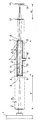
- the optical system according to the invention for laser marking comprises - when seen in the direction of a laser beam from a laser 1 - a focusing lens 2 situated coaxially to the laser beam of a preferably rectangular, and especially square transverse measurement.
- the lens 2 is preferably of a relatively long focal length a .
- a concave mirror 3 is situated with the vertex in the focal point of the lens, and the reflecting surface or mirror face 4 of said concave mirror faces away from the direction of the laser beam and is of a relatively large radius of curvature R4.
- An inlet opening 5 is shaped about the vertex of the concave mirror 3 and is congruent with the transverse measurement of the laser beam.
- the inlet opening 5 allows passage of the focusing laser beam and is of a transverse measurement slightly larger than the transverse measurement of the focal point.
- the side of the concave mirror 3 facing the focusing lens 2 comprises a frusto-conical surface 6 with its vertex adjacent the inlet opening. The frustoconical surface prevents the portions of the laser beam, which might incident on the edge of the inlet opening, from being reflected back into the laser and thereby from damaging said laser.
- a mask 7 with a reflecting surface or mirror face 9 facing the concave mirror is met by a mask 7 with a reflecting surface or mirror face 9 facing the concave mirror.
- the mask 7 may optionally comprise several mask portions or sections arranged behind one another and/or side by side.
- the distance b between the concave mirror 3 and the mask 7 corresponds in this embodiment substantially to the focal length a of the focusing lens 2, whereby the transverse measurement D1 of the laser beam on the mask corresponds substantially to the transverse measurement of the beam leaving the laser 1.
- a mask pattern or mask openings 8 are shaped in the mask 7, and the transverse measurement of this mask pattern is slightly smaller than the transverse measurement D1 of the laser beam on the mask.
- An elongated, straight, cylindrical waveguide 10 is co-axially situated between the concave mirror 3 and the mask 7.
- the waveguide is reflecting on its inner surface 11 and is of a transverse measurement being congruent with the transverse measurement of the laser beam.
- the inner transverse measurement D of the waveguide 10 corresponds substantially to twice the transverse measurement D1 of the laser beam on the mask 7.
- a portion of the laser beam being met by the mask 7 passes directly through the mask pattern or the mask openings 8, whereas the remaining portion of the laser beam is reflected by the surface 9 of the mask 7 and thereby directed back towards the reflecting surface 4 of the mirror 3.
- the reflecting surface 4 directs the light towards the mask 7, whereafter an additional portion of the laser beam passes through the mask pattern 8.
- the reflecting inner surface 11 of the waveguide 10 reflects the radiation reflected towards it by the reflecting surface 9 of the mask 7 or the reflecting surface 4.
- the waveguide 10 of a square transverse measurement tries in general to uniform the radiation or to concentrate said radiation farther away from the optical axis and thereby tries to provide a uniform distribution of energy across the mask 7.
- the latter implies furthermore that the laser radiation passing through the mask pattern 8 discloses a very uniform distribution of energy when being met by an image-producing lens 12.
- the image-producing lens 12 is situated coaxially to the optical axis after the mask 7 and produces an image 13 of the mask pattern 8 on the surface of the article 14 to be marked.
- a strong short laser pulse is employed, typically involving a pulse energy of about 0.5-20 joule and a pulse length of typically 10-1000 ns, the laser radiation evaporates a thin surface layer on the article and leaves an image of the mask on the article.
- the concave mirror 3, the cylindrical waveguide 10, and the mask 7 form a pressure chamber 15 which can be supplied with a protecting gas through an inlet opening 16.
- the protecting gas may leave the chamber 15 through both the inlet opening 5 of the concave mirror 3 and through the mask pattern 8 of the mask 7.
- the protecting gas prevents an undesired oxidation of the reflecting surfaces 4, 9, 11 and prevents plasma formation in the inlet opening 5 and the mask openings 8, as said plasma might otherwise shade these openings.
- Gases of a high ionic potential can be used as protecting gas.
- the entire optical system is situated in such a manner in a housing not shown that the components of the optical system can be very accurately adjusted, which ensures an optimum efficiency of the system and an optimum distribution of energy of the beam leaving the system.
- These adjustment possibilities include: The concave mirror 3 which can be tilted about its centre in two planes in order to optimize the resonator represented by the concave mirror 3 and the mask 7, the mask 7 which is also tiltable about its centre in two planes in order to optimize the above resonator, the lens 2 which can be moved in three axial directions in order to ensure a focusing of the laser beam in the inlet opening 5, the waveguide 10 which can be situated coaxial to the mirror 3 and the mask 7, the part of the optical system comprising the mirror 3, the waveguide 10, and the mask 7, and which can be tilted about the centre of the inlet opening 5 in two planes in order to ensure that the laser beam enters said part of the system at the correct angle, the image-producing lens 12 which can be correctly positioned in three axial directions relative to the
- the image-producing lens 12 may be replaced by more lenses arranged in succession in case the latter is considered advantageous.
- the reflecting surface of the concave mirror 3 may instead of being a continuous surface also comprise a plurality of small mirrors together forming the reflecting surface.
- lasers may be used which emit laser beams of other transverse measurements than the rectangular, such as circular, and the inlet opening and the waveguide may be of other transverse measurements neither congruent thereto nor mutually congruent.
- the waveguide can be completely omitted.
Landscapes
- Physics & Mathematics (AREA)
- Optics & Photonics (AREA)
- Engineering & Computer Science (AREA)
- Plasma & Fusion (AREA)
- Mechanical Engineering (AREA)
- Laser Beam Processing (AREA)
- Laser Surgery Devices (AREA)
- Lining Or Joining Of Plastics Or The Like (AREA)
- Glass Compositions (AREA)
- Preparing Plates And Mask In Photomechanical Process (AREA)
- Dot-Matrix Printers And Others (AREA)
Claims (11)
- Système optique destiné au marquage par un laser et comprenant dans la directon d'un faisceau lumineux ayant une section transversale prédéterminée (D₀) et émis par un laser (1)- un masque (7) ayant un motif (8) et un dispositif (12), tel qu'une lentille, destiné à créer une image, la section transversale (D1) du faisceau laser sur le masque (7) étant supérieure à la section transversale du motif (8) du masque, caractérisé en ce que
un dispositif (2) de focalisation, tel qu'une lentille, et un miroir concave (3) sont placés entre le laser (1) et le masque (7), le dispositif (2) de focalisation étant disposé afin qu'il focalise le faisceau émis par le laser (1) afin qu'il possède la section transversale (D1) sur le masque (7) après focalisation, le miroir concave (3) étant disposé afin que son sommet se trouve au foyer du dispositif (2) de focalisation et que sa surface réfléchissante (4) soit tournée vers le masque (7), une ouverture d'entrée (5) étant formée autour du sommet, la section transversale de l'ouverture d'entrée étant légèrement supérieure à la section transversale du foyer,
le masque (7) a la configuration d'un miroir, plan de préférence, dont la surface réfléchissante (9) est tournée vers le miroir concave (3), et
le rayon de courbure (R₄) du miroir concave (3) est supérieur au double de la distance (b) comprise entre le masque (7) et le miroir concave (3). - Système optique selon la revendication 1, caractérisé en ce que le rayon (R₄) de courbure du miroir concave (3) est pratiquement compris entre trois et dix fois la distance (b) comprise entre le miroir concave (3) et le masque (7).
- Système optique selon la revendication 1 ou 2, caractérisé en ce qu'un guide d'onde cylindrique, rectiligne et allongé (10) ayant une surface réfléchissante interne (11) est disposé coaxialement pratiquement entre le miroir concave (3) et le masque (7).
- Système optique selon la revendication 2, caractérisé en ce que la section transversale du guide d'onde cylindrique (10) correspond à 1 à 5 fois et de préférence à 1,5 à 2,5 fois la section transversale (D₁) du faisceau lumineux incident sur le masque (7).
- Système optique selon une ou plusieurs des revendications précédentes, caractérisé en ce que l'ouverture d'entrée (5) formée dans le miroir concave (3) et le guide d'onde (10) a une section transversale correspondant à celle du faisceau laser, la section transversale étant de préférence rectangulaire et en particulier carrée.
- Système optique suivant une ou plusieurs des revendications précédentes, caractérisé en ce que la distance (b) comprise entre le miroir concave (3) et le masque (7) correspond pratiquement à la distance focale (a) du dispositif de focalisation (2).
- Système optique selon une ou plusieurs des revendications précédentes, caractérisé en ce que le dispositif de focalisation (2) a une distance focale comprise entre 150 et 500 mm et de préférence entre 250 et 375 mm.
- Système optique selon une ou plusieurs des revendications précédentes, caractérisé en ce que, du côté tourné vers le dispositif de focalisation (2), le miroir concave (3) a une surface tronconique (6) ayant un sommet adjacent à l'ouverture d'entrée (5).
- Système optique selon une ou plusieurs des revendications précédentes, caractérisé en ce que le miroir concave (3), le guide d'onde cylindrique (10), et le masque (7) forment ensemble une chambre (15) sous pression qui peut recevoir un gaz protecteur.
- Système optique selon une ou plusieurs des revendications précédentes, caractérisé en ce que le dispositif (2) de focalisation et le dispositif (12) générateur d'une image forment des parois d'extrémité d'une chambre sous pression qui peut recevoir un gaz protecteur.
- Système optique selon une ou plusieurs des revendications précédentes, caractérisé en ce que la surface réfléchissante (4) du miroir concave (3) est formée par plusieurs petits segments de miroir plan.
Priority Applications (1)
| Application Number | Priority Date | Filing Date | Title |
|---|---|---|---|
| AT89900584T ATE82893T1 (de) | 1987-12-08 | 1988-12-02 | Optisches system fuer lasermarkierung. |
Applications Claiming Priority (2)
| Application Number | Priority Date | Filing Date | Title |
|---|---|---|---|
| DK6447/87 | 1987-12-08 | ||
| DK644787A DK160357C (da) | 1987-12-08 | 1987-12-08 | Optiksystem til lasermaerkning |
Publications (2)
| Publication Number | Publication Date |
|---|---|
| EP0396587A1 EP0396587A1 (fr) | 1990-11-14 |
| EP0396587B1 true EP0396587B1 (fr) | 1992-12-02 |
Family
ID=8148751
Family Applications (1)
| Application Number | Title | Priority Date | Filing Date |
|---|---|---|---|
| EP89900584A Expired - Lifetime EP0396587B1 (fr) | 1987-12-08 | 1988-12-02 | Systeme optique pour le marquage au laser |
Country Status (8)
| Country | Link |
|---|---|
| US (1) | US5011253A (fr) |
| EP (1) | EP0396587B1 (fr) |
| JP (1) | JP2662065B2 (fr) |
| AT (1) | ATE82893T1 (fr) |
| AU (1) | AU2826789A (fr) |
| DE (1) | DE3876452T2 (fr) |
| DK (1) | DK160357C (fr) |
| WO (1) | WO1989005208A1 (fr) |
Families Citing this family (11)
| Publication number | Priority date | Publication date | Assignee | Title |
|---|---|---|---|---|
| US4842782A (en) * | 1986-10-14 | 1989-06-27 | Allergan, Inc. | Manufacture of ophthalmic lenses by excimer laser |
| NL9002036A (nl) * | 1990-09-17 | 1992-04-16 | Philips Nv | Inrichting en werkwijze voor het met elektromagnetisch straling aanbrengen van merktekens op een voorwerp, en een voorwerp voorzien van merktekens. |
| EP0724498B1 (fr) * | 1993-09-30 | 1997-12-29 | Cymer, Inc. | Procedes et appareil ameliorant l'illumination de masques plein champ |
| US5768453A (en) * | 1994-12-13 | 1998-06-16 | Raytheon Company | Method and apparatus for concentrating and combining the energy of asymmetric diode laser beams |
| ES2112756B1 (es) * | 1995-05-23 | 1998-12-16 | Macsa Id Sa | Sistema de marcacion de puntos con laser. |
| EP0770925B1 (fr) * | 1995-10-11 | 2002-01-02 | SANYO ELECTRIC Co., Ltd. | Méthode et dispositif de traitement optique |
| DE19724061C2 (de) * | 1997-06-07 | 2001-11-22 | Univ Stuttgart Strahlwerkzeuge | Vorrichtung zur Laserbearbeitung eines Werkstückes |
| US6370837B1 (en) | 1999-08-04 | 2002-04-16 | Anthony B. Mcmahon | System for laying masonry blocks |
| US20030156819A1 (en) * | 2002-02-15 | 2003-08-21 | Mark Pruss | Optical waveguide |
| JP4494045B2 (ja) * | 2003-03-11 | 2010-06-30 | 株式会社半導体エネルギー研究所 | ビームホモジナイザ及びレーザ照射装置、並びに半導体装置の作製方法 |
| US7327916B2 (en) | 2003-03-11 | 2008-02-05 | Semiconductor Energy Laboratory Co., Ltd. | Beam Homogenizer, laser irradiation apparatus, and method of manufacturing a semiconductor device |
Family Cites Families (2)
| Publication number | Priority date | Publication date | Assignee | Title |
|---|---|---|---|---|
| AT329717B (de) * | 1973-03-28 | 1976-05-25 | Vianova Kunstharz Ag | Anordnung und verfahren zum harten von anstrichstoffen und uberzugen mittels von irasern emittierter infrarot-strahlung |
| US4480168A (en) * | 1982-03-29 | 1984-10-30 | Canadian Patents & Development Limited | Laser-surface coupler |
-
1987
- 1987-12-08 DK DK644787A patent/DK160357C/da not_active IP Right Cessation
-
1988
- 1988-12-02 DE DE8989900584T patent/DE3876452T2/de not_active Expired - Fee Related
- 1988-12-02 JP JP1500313A patent/JP2662065B2/ja not_active Expired - Lifetime
- 1988-12-02 AU AU28267/89A patent/AU2826789A/en not_active Abandoned
- 1988-12-02 WO PCT/DK1988/000201 patent/WO1989005208A1/fr not_active Ceased
- 1988-12-02 US US07/474,136 patent/US5011253A/en not_active Expired - Lifetime
- 1988-12-02 EP EP89900584A patent/EP0396587B1/fr not_active Expired - Lifetime
- 1988-12-02 AT AT89900584T patent/ATE82893T1/de active
Also Published As
| Publication number | Publication date |
|---|---|
| EP0396587A1 (fr) | 1990-11-14 |
| JPH03501466A (ja) | 1991-04-04 |
| DK160357B (da) | 1991-03-04 |
| DK644787A (da) | 1989-06-09 |
| JP2662065B2 (ja) | 1997-10-08 |
| WO1989005208A1 (fr) | 1989-06-15 |
| AU2826789A (en) | 1989-07-05 |
| US5011253A (en) | 1991-04-30 |
| DE3876452T2 (de) | 1993-06-09 |
| ATE82893T1 (de) | 1992-12-15 |
| DK160357C (da) | 1991-08-12 |
| DK644787D0 (da) | 1987-12-08 |
| DE3876452D1 (de) | 1993-01-14 |
Similar Documents
| Publication | Publication Date | Title |
|---|---|---|
| EP0080597B1 (fr) | Homogénéisateur pour un faisceau optique | |
| US6825440B2 (en) | Laser beam machining method and apparatus | |
| EP0396587B1 (fr) | Systeme optique pour le marquage au laser | |
| JPH11502792A (ja) | ノズルの形成方法および装置 | |
| JP2001500065A (ja) | レーザ装置 | |
| US20220234137A1 (en) | Laser processing head having a diaphragm to increase scan field of the laser beam | |
| US20040007563A1 (en) | Apparatus for and method of targeting | |
| KR100659438B1 (ko) | 레이저 가공 장치 및 레이저 가공 방법 | |
| AU725154B2 (en) | Method and apparatus for laser imaging with multi-mode devices and optical diffusers | |
| US20060114772A1 (en) | Laser processing device | |
| JPH07333540A (ja) | レーザ・スキャナ装置 | |
| US4902084A (en) | Optical scanning system | |
| CN117103684B (zh) | 一种降低长工作距离振镜惯量的扫描系统 | |
| US20070000887A1 (en) | Method for scan welding or marking through a waveguide and waveguide therefor | |
| CA1317642C (fr) | Systeme optique pour marquage au laser | |
| US20220395925A1 (en) | Method for laser machining a workpiece and associated laser machining system | |
| JP2002316291A (ja) | レーザ加工機 | |
| JP2005103630A (ja) | レーザ加工装置及びレーザ加工方法 | |
| JPH09122950A (ja) | 複合溶接ヘッド | |
| JP2817555B2 (ja) | レーザ加工機 | |
| JP7555247B2 (ja) | レーザビーム照射用光学ユニット及びレーザ加工装置 | |
| JPH0919785A (ja) | レーザ加工用光学系及びそれを用いた加工方法 | |
| CN115003449A (zh) | 用于激光加工工件的方法和用于激光加工工件的设备 | |
| JP3006348B2 (ja) | レーザ加工装置 | |
| JP2006326673A (ja) | レーザ加工装置及びレーザ加工方法 |
Legal Events
| Date | Code | Title | Description |
|---|---|---|---|
| PUAI | Public reference made under article 153(3) epc to a published international application that has entered the european phase |
Free format text: ORIGINAL CODE: 0009012 |
|
| 17P | Request for examination filed |
Effective date: 19900517 |
|
| AK | Designated contracting states |
Kind code of ref document: A1 Designated state(s): AT BE CH DE FR GB IT LI LU NL SE |
|
| 17Q | First examination report despatched |
Effective date: 19910731 |
|
| RAP1 | Party data changed (applicant data changed or rights of an application transferred) |
Owner name: DANLASER A/S |
|
| GRAA | (expected) grant |
Free format text: ORIGINAL CODE: 0009210 |
|
| RAP1 | Party data changed (applicant data changed or rights of an application transferred) |
Owner name: INSTITUTTET FOR PRODUKTUDVIKLING |
|
| AK | Designated contracting states |
Kind code of ref document: B1 Designated state(s): AT BE CH DE FR GB IT LI LU NL SE |
|
| PG25 | Lapsed in a contracting state [announced via postgrant information from national office to epo] |
Ref country code: IT Free format text: LAPSE BECAUSE OF FAILURE TO SUBMIT A TRANSLATION OF THE DESCRIPTION OR TO PAY THE FEE WITHIN THE PRE;WARNING: LAPSES OF ITALIAN PATENTS WITH EFFECTIVE DATE BEFORE 2007 MAY HAVE OCCURRED AT ANY TIME BEFORE 2007. THE CORRECT EFFECTIVE DATE MAY BE DIFFERENT FROM THE ONE RECORDED.SCRIBED TIME-LIMIT Effective date: 19921202 Ref country code: SE Effective date: 19921202 Ref country code: LI Effective date: 19921202 Ref country code: NL Effective date: 19921202 Ref country code: AT Effective date: 19921202 Ref country code: CH Effective date: 19921202 Ref country code: BE Effective date: 19921202 |
|
| REF | Corresponds to: |
Ref document number: 82893 Country of ref document: AT Date of ref document: 19921215 Kind code of ref document: T |
|
| PG25 | Lapsed in a contracting state [announced via postgrant information from national office to epo] |
Ref country code: LU Free format text: LAPSE BECAUSE OF NON-PAYMENT OF DUE FEES Effective date: 19921231 |
|
| REF | Corresponds to: |
Ref document number: 3876452 Country of ref document: DE Date of ref document: 19930114 |
|
| REG | Reference to a national code |
Ref country code: CH Ref legal event code: PL |
|
| EN | Fr: translation not filed | ||
| PG25 | Lapsed in a contracting state [announced via postgrant information from national office to epo] |
Ref country code: FR Effective date: 19930423 |
|
| NLV1 | Nl: lapsed or annulled due to failure to fulfill the requirements of art. 29p and 29m of the patents act | ||
| PLBE | No opposition filed within time limit |
Free format text: ORIGINAL CODE: 0009261 |
|
| STAA | Information on the status of an ep patent application or granted ep patent |
Free format text: STATUS: NO OPPOSITION FILED WITHIN TIME LIMIT |
|
| 26N | No opposition filed | ||
| REG | Reference to a national code |
Ref country code: FR Ref legal event code: ST |
|
| REG | Reference to a national code |
Ref country code: GB Ref legal event code: IF02 |
|
| PGFP | Annual fee paid to national office [announced via postgrant information from national office to epo] |
Ref country code: GB Payment date: 20021126 Year of fee payment: 15 |
|
| PGFP | Annual fee paid to national office [announced via postgrant information from national office to epo] |
Ref country code: DE Payment date: 20021223 Year of fee payment: 15 |
|
| PG25 | Lapsed in a contracting state [announced via postgrant information from national office to epo] |
Ref country code: GB Free format text: LAPSE BECAUSE OF NON-PAYMENT OF DUE FEES Effective date: 20031202 |
|
| PG25 | Lapsed in a contracting state [announced via postgrant information from national office to epo] |
Ref country code: DE Free format text: LAPSE BECAUSE OF NON-PAYMENT OF DUE FEES Effective date: 20040701 |
|
| GBPC | Gb: european patent ceased through non-payment of renewal fee |
Effective date: 20031202 |