EP0397058A2 - Electrovanne d'échappement pour une nourrice - Google Patents
Electrovanne d'échappement pour une nourrice Download PDFInfo
- Publication number
- EP0397058A2 EP0397058A2 EP90108466A EP90108466A EP0397058A2 EP 0397058 A2 EP0397058 A2 EP 0397058A2 EP 90108466 A EP90108466 A EP 90108466A EP 90108466 A EP90108466 A EP 90108466A EP 0397058 A2 EP0397058 A2 EP 0397058A2
- Authority
- EP
- European Patent Office
- Prior art keywords
- armature
- bore
- stator
- valve
- solenoid assembly
- Prior art date
- Legal status (The legal status is an assumption and is not a legal conclusion. Google has not performed a legal analysis and makes no representation as to the accuracy of the status listed.)
- Granted
Links
- 238000010926 purge Methods 0.000 title description 8
- 238000010521 absorption reaction Methods 0.000 claims abstract description 3
- 230000006872 improvement Effects 0.000 claims description 6
- OKTJSMMVPCPJKN-UHFFFAOYSA-N Carbon Chemical compound [C] OKTJSMMVPCPJKN-UHFFFAOYSA-N 0.000 description 3
- 229910052799 carbon Inorganic materials 0.000 description 3
- 239000000446 fuel Substances 0.000 description 3
- 230000008901 benefit Effects 0.000 description 2
- 238000000034 method Methods 0.000 description 2
- UQMRAFJOBWOFNS-UHFFFAOYSA-N butyl 2-(2,4-dichlorophenoxy)acetate Chemical compound CCCCOC(=O)COC1=CC=C(Cl)C=C1Cl UQMRAFJOBWOFNS-UHFFFAOYSA-N 0.000 description 1
- 238000010276 construction Methods 0.000 description 1
- 238000010586 diagram Methods 0.000 description 1
- 239000013536 elastomeric material Substances 0.000 description 1
- 229920005560 fluorosilicone rubber Polymers 0.000 description 1
- 239000000463 material Substances 0.000 description 1
- 230000013011 mating Effects 0.000 description 1
- 239000002184 metal Substances 0.000 description 1
- 238000000465 moulding Methods 0.000 description 1
- 230000008569 process Effects 0.000 description 1
- 230000009467 reduction Effects 0.000 description 1
- 230000000717 retained effect Effects 0.000 description 1
Images
Classifications
-
- F—MECHANICAL ENGINEERING; LIGHTING; HEATING; WEAPONS; BLASTING
- F16—ENGINEERING ELEMENTS AND UNITS; GENERAL MEASURES FOR PRODUCING AND MAINTAINING EFFECTIVE FUNCTIONING OF MACHINES OR INSTALLATIONS; THERMAL INSULATION IN GENERAL
- F16K—VALVES; TAPS; COCKS; ACTUATING-FLOATS; DEVICES FOR VENTING OR AERATING
- F16K31/00—Actuating devices; Operating means; Releasing devices
- F16K31/02—Actuating devices; Operating means; Releasing devices electric; magnetic
- F16K31/06—Actuating devices; Operating means; Releasing devices electric; magnetic using a magnet, e.g. diaphragm valves, cutting off by means of a liquid
- F16K31/0686—Braking, pressure equilibration, shock absorbing
- F16K31/0696—Shock absorbing, e.g. using a dash-pot
Definitions
- This invention relates to a canister purge solenoid valve. More especially, the invention relates to an improvement for reducing wear and operating noise in such a valve.
- a canister purge solenoid valve is a device that is used in certain evaporative emission control systems of automotive vehicles. Its purpose is to control the flow of fuel vapors from a collection canister, commonly called a carbon canister, to the engine intake manifold. The flow is controlled by means of a pulse width modulated signal that is applied to the valve's solenoid from the engine computer. This in turn produces a corresponding modulation of the valve so that the average open time for the valve during each cycle of the modulating signal is similarly modulated.
- Evaporative emission standards for automotive vehicles are established by government regulations. Due to changes in applicable standards, evaporative emission systems are required to remove increased amounts of fuel vapors from carbon canisters. Accordingly, it has been necessary to increase the size of the canister purge solenoid valve. Two undesired results of the solenoid valve enlargement are an increase in operating noise level and increased wear on the solenoid's plunger (armature).
- the present invention relates to a new and unique construction that is effective to reduce both the operating noise level and the armature wear.
- the elastomeric valve head that opens and closes against the valve seat as the arnature is reciprocated, is configured to form one travel stop for the armature during retraction, and an elastomeric member is disposed between the opposite end of the armature and the stator to form a second travel stop.
- the two travel stops are arranged such that the first travel stop is effective upon armature retraction to begin absorbing the armature momentum just slightly before the second armature stop. The result is a significant reduction in operating noise level and improved durability for the second travel stop.
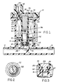
- Fig. 1 shows a canister purge solenoid valve 10 embodying principles of the invention.
- Valve 10 comprises an inlet 12 that is adapted to be connected to a carbon canister and an outlet 14 that is adapted to be connected to intake manifold vacuum. Between inlet 12 and outlet 14 is a valve seat 16.
- the inlet, outlet, and valve seat are part of the valve body which includes a cylindrical wall 18 that is perpendicular to the inlet and outlet.
- a solenoid assembly 20 is disposed within wall 18.
- Solenoid assembly 20 comprises a plastic bobbin 22 having a circular, cylindrical bore 24.
- An electric solenoid coil 26 is wound on bobbin 22 between bobbin flanges 28, 30.
- the bobbin has a third flange 32 at the end of bore 24 confronting seat 16.
- the solenoid assembly further comprises a magnetically conductive stator 34 that is fitted into the upper end of bore 24.
- the stator has a lip 36 that traps a magnetically conductive member 38 against the upper end of the bobbin bore.
- a magnetically conductive shell 40 fits over washer 38 and around the outside of the solenoid assembly. This shell has barbed lower ends 42 (Fig. 4) that are press-fitted into slots 44 in the valve body to cause the solenoid assembly to be retained within wall 18.
- a cap 46 which includes a connector plug structure 48 containing terminals 50 to which the ends of solenoid coil 26 are connected.
- Connector plug structure 48 is adapted to be connected to a mating plug (not shown) that leads to the engine computer.
- the computer sends a pulse width modulated signal to valve 10 that pulse width modulates coil 26.
- the solenoid assembly still further includes a magnetically conductive member 52 disposed between flanges 30 and 32, and an armature 54 that has a sliding fit within the lower end of bore 24.
- a helical spring 56 that is disposed between stator 34 and armature 54 biases the armature away from the stator so that when the solenoid coil is not energized, an elastomeric valve head 58 that is at the end of the armature is forced against seat 16 to block flow between inlet 12 and outlet 14.
- armature 54 is increasingly retracted into bore 24, compressing spring 56 in the process and unseating valve head 58 from seat 16 so that flow can occur from inlet 12 to outlet 14.
- valve head 58 is constructed to have particular relationships with bobbin 22. Specifically, the valve head radially overlaps flange 32, and it is made thick enough, so that when the solenoid coil is energized to retract the armature, the outer margin of the valve head will abut a margin of flange 32 around bore 24. Moreover, such abutment will take place initially just before an elastomeric limit stop 60 at the opposite end of armature 54 abuts the confronting end of stator 34. Limit stop 60 is fitted into a coaxial depression in the end of the armature such that a portion of the limit stop protrudes from the end of the armature.
- limit stop 60 It is this protruding portion of limit stop 60 that impacts stator 34 when the armature is retracted so that metal-to-metal contact between armature and stator is avoided.
- the valve head When the armature is retracted, the valve head functions to initially absorb some of the momentum of the armature before limit stop 60 contacts stator 34. Hence the full impact is not absorbed by limit stop 60 alone, but rather the final impact absorption is shared by the valve head 58 and the limit stop 60 after the initial impact has been absorbed by valve head 58. The result is a quieter valve operation and reduced wear on limit stop 60.
- the elastomeric material for the valve head is preferably one that is resistant to fuels, and fluorosilicone rubber is one suitable material.
- Both the valve head and the limit stop can be insert molded onto armature 54 by conventional insert molding techniques.
- the end of the armature contains a circumferential flange 62 so that after valve head 58 has been molded, flange 62 is received in a circumferential groove 64 formed in valve head 58.
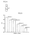
- Fig. 5 is a graph that compares the operating noise level of valve 10 with the noise levels of other commercial canister purge valves.
- Valve 10 is designated BRAND S in the graph, and the graph shows that valve 10 has a significantly lower operating noise level than the other valves under the same test conditions.
- the invention provides a meaningful improvement in canister purge solenoid valves.
Landscapes
- Engineering & Computer Science (AREA)
- General Engineering & Computer Science (AREA)
- Mechanical Engineering (AREA)
- Magnetically Actuated Valves (AREA)
- Supplying Secondary Fuel Or The Like To Fuel, Air Or Fuel-Air Mixtures (AREA)
Applications Claiming Priority (2)
| Application Number | Priority Date | Filing Date | Title |
|---|---|---|---|
| US07/350,430 US4901974A (en) | 1989-05-11 | 1989-05-11 | Canister purge solenoid valve |
| US350430 | 1989-05-11 |
Publications (3)
| Publication Number | Publication Date |
|---|---|
| EP0397058A2 true EP0397058A2 (fr) | 1990-11-14 |
| EP0397058A3 EP0397058A3 (fr) | 1991-05-22 |
| EP0397058B1 EP0397058B1 (fr) | 1994-08-24 |
Family
ID=23376685
Family Applications (1)
| Application Number | Title | Priority Date | Filing Date |
|---|---|---|---|
| EP90108466A Expired - Lifetime EP0397058B1 (fr) | 1989-05-11 | 1990-05-04 | Electrovanne d'échappement pour une nourrice |
Country Status (4)
| Country | Link |
|---|---|
| US (1) | US4901974A (fr) |
| EP (1) | EP0397058B1 (fr) |
| JP (1) | JPH03117791A (fr) |
| DE (1) | DE69011728T2 (fr) |
Cited By (5)
| Publication number | Priority date | Publication date | Assignee | Title |
|---|---|---|---|---|
| FR2745058A1 (fr) * | 1996-02-15 | 1997-08-22 | Eaton Sa Monaco | Electrovanne de regulation pour circuit de fluide, notamment gazeux |
| DE19730276A1 (de) * | 1997-07-15 | 1999-01-21 | Wabco Gmbh | Einrichtung mit wenigstens zwei relativ zueinander beweglichen Teilen |
| EP1286093A1 (fr) * | 2001-08-08 | 2003-02-26 | Delphi Technologies, Inc. | Soupape électromagnetique à amortisseur |
| US9038605B2 (en) | 2012-09-19 | 2015-05-26 | Ford Global Technologies, Llc | Purge valve noise attenuation system and method |
| WO2018141468A1 (fr) | 2017-02-06 | 2018-08-09 | Mmt ag | Vanne motorisee a boisseau |
Families Citing this family (38)
| Publication number | Priority date | Publication date | Assignee | Title |
|---|---|---|---|---|
| DE9014763U1 (de) * | 1990-10-25 | 1991-01-10 | Schultz, Wolfgang E., Dipl.-Ing., 8940 Memmingen | Elektromagnet |
| US5183022A (en) * | 1991-07-16 | 1993-02-02 | Siemens Automotive Limited | Multi-slope canister purge solenoid valve |
| US5237980A (en) * | 1992-12-02 | 1993-08-24 | Siemens Automotive Limited | On-board fuel vapor recovery system having improved canister purging |
| DE4244113A1 (de) * | 1992-12-24 | 1994-06-30 | Bosch Gmbh Robert | Ventil zum dosierten Einleiten von verflüchtigtem Brennstoff in einen Ansaugkanal einer Brennkraftmaschine |
| US5325838A (en) * | 1993-05-28 | 1994-07-05 | Bennett David E | Liquified petroleum gas fuel injector |
| US5538219A (en) * | 1994-12-16 | 1996-07-23 | Borg-Warner Automotive, Inc. | Reduced noise solenoid valve |
| JPH08320085A (ja) * | 1995-05-26 | 1996-12-03 | Aisan Ind Co Ltd | 電磁弁 |
| US5579741A (en) * | 1995-11-30 | 1996-12-03 | Siemens Electric Limited | Vapor purge valve having tapered bead armature seal |
| DE19626290A1 (de) * | 1996-07-01 | 1998-01-08 | Freudenberg Carl Fa | Elektromagnetisches Ventil |
| FR2761447A1 (fr) * | 1997-03-26 | 1998-10-02 | Eaton Sa Monaco | Electrovanne cyclee de regulation de debit de fluide |
| CA2289859A1 (fr) | 1997-05-13 | 1998-11-19 | Bennett Technologies, L.L.C. | Systeme et procede d'alimentation en gaz de petrole liquefie |
| US5967487A (en) * | 1997-08-25 | 1999-10-19 | Siemens Canada Ltd. | Automotive emission control valve with a cushion media |
| US6227173B1 (en) | 1999-06-07 | 2001-05-08 | Bi-Phase Technologies, L.L.C. | Fuel line arrangement for LPG system, and method |
| US6374847B1 (en) * | 1999-08-30 | 2002-04-23 | Daimlerchrysler Corporation | Seal cleansing routine |
| US6722626B2 (en) * | 2000-08-14 | 2004-04-20 | Siemens Automotive Inc. | Valve providing increase in flow for increase in power level |
| US6453930B1 (en) | 2000-09-09 | 2002-09-24 | Kelsey-Hayes Company | Control valves for a hydraulic control unit and method of assembly |
| US6679567B1 (en) * | 2000-09-09 | 2004-01-20 | Kelsey-Hayes Company | Control valve with overmolded armature for a hydraulic control unit |
| KR100463127B1 (ko) * | 2001-09-27 | 2004-12-23 | 현대자동차주식회사 | 퍼지콘트롤 솔레노이드밸브의 결합구조 |
| US6805331B2 (en) * | 2001-12-07 | 2004-10-19 | Delphi Technologies, Inc. | Electromagnetically energized actuator |
| US6955337B2 (en) * | 2003-04-03 | 2005-10-18 | Delphi Technologies, Inc. | Pneumatic module |
| US20050056800A1 (en) * | 2003-08-20 | 2005-03-17 | Modien Russell Miles | Automotive emission control valve having impact noise attenuation feature for the armature |
| JP2006153177A (ja) * | 2004-11-30 | 2006-06-15 | Keihin Corp | 燃料電池用電磁弁 |
| KR100775337B1 (ko) * | 2007-02-28 | 2007-11-08 | 주식회사 케피코 | 스토퍼리스 타입 퍼지 컨트롤 솔레노이드 밸브 |
| DE102009041188A1 (de) * | 2009-09-14 | 2011-03-24 | Svm Schultz Verwaltungs-Gmbh & Co. Kg | Elektromagnet mit einem Anker |
| DE102009029565A1 (de) * | 2009-09-18 | 2011-03-31 | Robert Bosch Gmbh | Magnetbaugruppe für ein Magnetventil und korrespondierendes Magnetventil |
| US8342479B2 (en) * | 2010-12-29 | 2013-01-01 | Shih Shih Technology Co., Ltd. | Solenoid controlled valve for fluid media |
| KR101147192B1 (ko) * | 2011-11-11 | 2012-05-25 | 주식회사 엘에스테크 | 웨이퍼 표면상의 증착 이물 제거 장치 |
| US9127605B2 (en) | 2012-03-21 | 2015-09-08 | Ford Global Technologies, Llc | Vapor recovery system purge valve and method |
| FR2996234B1 (fr) * | 2012-10-01 | 2014-09-26 | Seb Sa | Appareil de repassage comprenant une cuve pour la generation de vapeur sous pression equipee d'une electrovanne |
| US9631736B2 (en) | 2013-06-10 | 2017-04-25 | Walbro Llc | Low cost solenoid valve |
| US10993546B2 (en) | 2016-10-28 | 2021-05-04 | Sleep Number Corporation | Noise reducing plunger |
| KR20180065304A (ko) * | 2016-12-07 | 2018-06-18 | 현대자동차주식회사 | 솔레노이드 밸브 |
| KR102392753B1 (ko) * | 2017-09-25 | 2022-05-03 | 주식회사 만도 | 브레이크 시스템용 솔레노이드 밸브 |
| DE102020124586B4 (de) | 2020-09-22 | 2025-07-31 | Eagle Actuator Components Gmbh & Co. Kg | Elektromagnetisch betätigbares Ventil mit Polplatte und Verwendung des Ventils als Regenerierventil |
| US11832728B2 (en) | 2021-08-24 | 2023-12-05 | Sleep Number Corporation | Controlling vibration transmission within inflation assemblies |
| US12663094B2 (en) | 2023-09-18 | 2026-06-23 | Sleep Number Corporation | Plunger with rear facing bumper for air manifold |
| CN120083853A (zh) * | 2023-12-01 | 2025-06-03 | 帕德米尼Vna机电一体化有限公司 | 噪声阻尼器集成电磁阀 |
| WO2025218700A1 (fr) * | 2024-04-18 | 2025-10-23 | 浙江盾安人工环境股份有限公司 | Procédé de fabrication d'ensemble siège de soupape, ensemble siège de soupape et soupape électrique |
Family Cites Families (5)
| Publication number | Priority date | Publication date | Assignee | Title |
|---|---|---|---|---|
| DE975662C (de) * | 1951-02-18 | 1962-04-12 | Concordia Maschinen Und Elek Z | Anker fuer Magnetventile |
| US3013768A (en) * | 1959-12-03 | 1961-12-19 | Valcor Eng Corp | Solenoid and plunger |
| DE1283060B (de) * | 1965-11-04 | 1968-11-14 | Danfoss As | Magnetventil fuer Gase |
| FR2530771A1 (fr) * | 1982-07-21 | 1984-01-27 | Sibe | Electrovanne a obturateur plastique |
| US4582294A (en) * | 1985-04-01 | 1986-04-15 | Honeywell Inc. | Three-way solenoid valve |
-
1989
- 1989-05-11 US US07/350,430 patent/US4901974A/en not_active Expired - Lifetime
-
1990
- 1990-05-04 EP EP90108466A patent/EP0397058B1/fr not_active Expired - Lifetime
- 1990-05-04 DE DE69011728T patent/DE69011728T2/de not_active Expired - Fee Related
- 1990-05-11 JP JP2120143A patent/JPH03117791A/ja active Pending
Cited By (9)
| Publication number | Priority date | Publication date | Assignee | Title |
|---|---|---|---|---|
| FR2745058A1 (fr) * | 1996-02-15 | 1997-08-22 | Eaton Sa Monaco | Electrovanne de regulation pour circuit de fluide, notamment gazeux |
| EP0790449A3 (fr) * | 1996-02-15 | 1998-04-29 | Eaton S.A.M. | Electrovanne de régulation pour circuit de fluide, notamment gazeux |
| US6105931A (en) * | 1997-07-05 | 2000-08-22 | Wabco Gmbh | Wear-resistant valve apparatus |
| DE19730276A1 (de) * | 1997-07-15 | 1999-01-21 | Wabco Gmbh | Einrichtung mit wenigstens zwei relativ zueinander beweglichen Teilen |
| EP1286093A1 (fr) * | 2001-08-08 | 2003-02-26 | Delphi Technologies, Inc. | Soupape électromagnetique à amortisseur |
| US6595485B2 (en) | 2001-08-08 | 2003-07-22 | Delphi Technologies, Inc. | Solenoid valve with cushion between plunger and plunger stop |
| US9038605B2 (en) | 2012-09-19 | 2015-05-26 | Ford Global Technologies, Llc | Purge valve noise attenuation system and method |
| WO2018141468A1 (fr) | 2017-02-06 | 2018-08-09 | Mmt ag | Vanne motorisee a boisseau |
| US11668407B2 (en) | 2017-02-06 | 2023-06-06 | Mmt ag | Motorised ball valve |
Also Published As
| Publication number | Publication date |
|---|---|
| DE69011728D1 (de) | 1994-09-29 |
| EP0397058B1 (fr) | 1994-08-24 |
| US4901974A (en) | 1990-02-20 |
| JPH03117791A (ja) | 1991-05-20 |
| DE69011728T2 (de) | 1995-02-02 |
| EP0397058A3 (fr) | 1991-05-22 |
Similar Documents
| Publication | Publication Date | Title |
|---|---|---|
| US4901974A (en) | Canister purge solenoid valve | |
| US5326070A (en) | Solenoid valve | |
| US7270310B2 (en) | Electromagnetic valve and vapor fuel treating system applying the same | |
| US5579741A (en) | Vapor purge valve having tapered bead armature seal | |
| US6273396B1 (en) | Electromagnetic valve | |
| US5809977A (en) | Valve for metered introduction of volatilized fuel | |
| EP0778921B1 (fr) | Dispositif de pompage | |
| US6415817B1 (en) | Valve for dosing the admission of volatilized fuel | |
| US5328100A (en) | Modified armature for low noise injector | |
| EP0628137B1 (fr) | Soupape pour l'injection de doses de carburant vaporise dans une conduite d'admission d'un moteur a combustion interne | |
| EP0803025A1 (fr) | Pompe de detection de fuites a obturateur d'event solidaire | |
| JP2001514364A (ja) | 緩衝媒体を備えた自動車の排出物制御バルブ | |
| CA1125121A (fr) | Systemes d'injection de carburant | |
| EP1286093A1 (fr) | Soupape électromagnetique à amortisseur | |
| US6253789B1 (en) | Valve for metered introduction of volatilized fuel | |
| US6321725B1 (en) | Valve for metered introduction of evaporated fuel | |
| US5086980A (en) | Fuel injector for an internal combustion engine | |
| US6651951B2 (en) | Magnetic valve | |
| US7147202B2 (en) | Tank vent valve | |
| JP3778882B2 (ja) | 電磁アクチュエータ | |
| JP2004518862A (ja) | 燃料噴射弁 | |
| EP1205660A2 (fr) | Valve solénoide à bas courant | |
| US6530558B1 (en) | Valve for metered introduction of evaporated fuel into an intake conduit of an internal combustion engine | |
| CN209925629U (zh) | 碳罐电磁阀 | |
| US6016793A (en) | Leak detection module having electric-operated toggle levers for pump and valve |
Legal Events
| Date | Code | Title | Description |
|---|---|---|---|
| PUAI | Public reference made under article 153(3) epc to a published international application that has entered the european phase |
Free format text: ORIGINAL CODE: 0009012 |
|
| AK | Designated contracting states |
Kind code of ref document: A2 Designated state(s): DE FR GB |
|
| 17P | Request for examination filed |
Effective date: 19901205 |
|
| PUAL | Search report despatched |
Free format text: ORIGINAL CODE: 0009013 |
|
| AK | Designated contracting states |
Kind code of ref document: A3 Designated state(s): DE FR GB |
|
| 17Q | First examination report despatched |
Effective date: 19930319 |
|
| GRAA | (expected) grant |
Free format text: ORIGINAL CODE: 0009210 |
|
| AK | Designated contracting states |
Kind code of ref document: B1 Designated state(s): DE FR GB |
|
| REF | Corresponds to: |
Ref document number: 69011728 Country of ref document: DE Date of ref document: 19940929 |
|
| ET | Fr: translation filed | ||
| PLBE | No opposition filed within time limit |
Free format text: ORIGINAL CODE: 0009261 |
|
| STAA | Information on the status of an ep patent application or granted ep patent |
Free format text: STATUS: NO OPPOSITION FILED WITHIN TIME LIMIT |
|
| 26N | No opposition filed | ||
| PGFP | Annual fee paid to national office [announced via postgrant information from national office to epo] |
Ref country code: GB Payment date: 19980414 Year of fee payment: 9 |
|
| PGFP | Annual fee paid to national office [announced via postgrant information from national office to epo] |
Ref country code: FR Payment date: 19980529 Year of fee payment: 9 |
|
| PG25 | Lapsed in a contracting state [announced via postgrant information from national office to epo] |
Ref country code: GB Free format text: LAPSE BECAUSE OF NON-PAYMENT OF DUE FEES Effective date: 19990504 |
|
| GBPC | Gb: european patent ceased through non-payment of renewal fee |
Effective date: 19990504 |
|
| PG25 | Lapsed in a contracting state [announced via postgrant information from national office to epo] |
Ref country code: FR Free format text: LAPSE BECAUSE OF NON-PAYMENT OF DUE FEES Effective date: 20000131 |
|
| REG | Reference to a national code |
Ref country code: FR Ref legal event code: ST |
|
| PGFP | Annual fee paid to national office [announced via postgrant information from national office to epo] |
Ref country code: DE Payment date: 20040719 Year of fee payment: 15 |
|
| PG25 | Lapsed in a contracting state [announced via postgrant information from national office to epo] |
Ref country code: DE Free format text: LAPSE BECAUSE OF NON-PAYMENT OF DUE FEES Effective date: 20051201 |