EP0397223A2 - Heizkörperhaltering und Verfahren und Matrize zur Herstellung dieses Halterings - Google Patents
Heizkörperhaltering und Verfahren und Matrize zur Herstellung dieses Halterings Download PDFInfo
- Publication number
- EP0397223A2 EP0397223A2 EP90200263A EP90200263A EP0397223A2 EP 0397223 A2 EP0397223 A2 EP 0397223A2 EP 90200263 A EP90200263 A EP 90200263A EP 90200263 A EP90200263 A EP 90200263A EP 0397223 A2 EP0397223 A2 EP 0397223A2
- Authority
- EP
- European Patent Office
- Prior art keywords
- ring
- core
- rings
- punch
- diameter
- Prior art date
- Legal status (The legal status is an assumption and is not a legal conclusion. Google has not performed a legal analysis and makes no representation as to the accuracy of the status listed.)
- Granted
Links
Images
Classifications
-
- F—MECHANICAL ENGINEERING; LIGHTING; HEATING; WEAPONS; BLASTING
- F28—HEAT EXCHANGE IN GENERAL
- F28F—DETAILS OF HEAT-EXCHANGE AND HEAT-TRANSFER APPARATUS, OF GENERAL APPLICATION
- F28F9/00—Casings; Header boxes; Auxiliary supports for elements; Auxiliary members within casings
- F28F9/26—Arrangements for connecting different sections of heat-exchange elements, e.g. of radiators
- F28F9/262—Arrangements for connecting different sections of heat-exchange elements, e.g. of radiators for radiators
-
- B—PERFORMING OPERATIONS; TRANSPORTING
- B21—MECHANICAL METAL-WORKING WITHOUT ESSENTIALLY REMOVING MATERIAL; PUNCHING METAL
- B21D—WORKING OR PROCESSING OF SHEET METAL OR METAL TUBES, RODS OR PROFILES WITHOUT ESSENTIALLY REMOVING MATERIAL; PUNCHING METAL
- B21D53/00—Making other particular articles
- B21D53/02—Making other particular articles heat exchangers or parts thereof, e.g. radiators, condensers fins, headers
-
- B—PERFORMING OPERATIONS; TRANSPORTING
- B21—MECHANICAL METAL-WORKING WITHOUT ESSENTIALLY REMOVING MATERIAL; PUNCHING METAL
- B21D—WORKING OR PROCESSING OF SHEET METAL OR METAL TUBES, RODS OR PROFILES WITHOUT ESSENTIALLY REMOVING MATERIAL; PUNCHING METAL
- B21D53/00—Making other particular articles
- B21D53/16—Making other particular articles rings, e.g. barrel hoops
-
- F—MECHANICAL ENGINEERING; LIGHTING; HEATING; WEAPONS; BLASTING
- F28—HEAT EXCHANGE IN GENERAL
- F28D—HEAT-EXCHANGE APPARATUS, NOT PROVIDED FOR IN ANOTHER SUBCLASS, IN WHICH THE HEAT-EXCHANGE MEDIA DO NOT COME INTO DIRECT CONTACT
- F28D21/00—Heat-exchange apparatus not covered by any of the groups F28D1/00 - F28D20/00
- F28D2021/0019—Other heat exchangers for particular applications; Heat exchange systems not otherwise provided for
- F28D2021/0035—Other heat exchangers for particular applications; Heat exchange systems not otherwise provided for for domestic or space heating, e.g. heating radiators
-
- F—MECHANICAL ENGINEERING; LIGHTING; HEATING; WEAPONS; BLASTING
- F28—HEAT EXCHANGE IN GENERAL
- F28F—DETAILS OF HEAT-EXCHANGE AND HEAT-TRANSFER APPARATUS, OF GENERAL APPLICATION
- F28F2240/00—Spacing means
Definitions
- the invention relates to a support ring by means of which it is possible to fix supply and evacuation pipes by butt welds to the heating radiators.
- the invention also relates to a method and a matrix for the production of said support ring.
- Support rings are known which are turned from a piece of metal and whose external diameter is preferably 23.7 mm, the internal diameter of 13 mm and the thickness of 11.4 mm. These rings are then generally provided with four radially oriented holes.
- a support ring is produced which consists of at least two rings folded and pressed one inside the other with a metallic strip, by example of steel strip, and in which the radial openings are previously punched in the steel strip.
- these rings When making these rings, no waste is formed and the production speed is considerably increased. In addition, these rings are to be manufactured at a cost price significantly lower than that of traditional rings.
- the method used in this case according to the invention to obtain the new support ring consists in cutting a flat metal strip whose length is equal to the circumference of the outer ring, in cutting a second flat metal strip whose length is equal to the circumference of the inner ring, to fold the two ends of the two ribbons into an arc, to press transversely the first ribbon previously folded against and around a part of a core whose diameter is equal to inner diameter of the outer ring of the support ring, transversely pressing the second previously folded ribbon against and around a part of said core whose diameter is equal to the inner diameter of the inner ring of the support ring thus formed on the core, pressing the inner ring axially in the outer ring and pressing the two rings one on the other to measure.
- the ends of the first ribbon are folded in an arc of a circle whose radius is equal to half the outside diameter of the outer ring and the ends of the second ribbon are folded in an arc of circle whose radius is equal to the half the outside diameter of the inside ring.
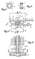
- the support ring 1 consists of an inner ring 2 folded with a flat steel strip and a larger outer ring 3 also folded with a steel strip dish.
- this steel strip are punched holes 4 which are oriented diametrically two by two when the rings are formed. After the formation of these rings 2-3, they are pressed one inside the other and one on the other, so that in a simple and inexpensive way one obtains a support ring which satisfies all the requirements formulated.
- This matrix has a cylindrical core 5 with a cylindrical part 6 whose diameter corresponds to inner diameter of the inner ring 2 and a second cylindrical part 7 whose diameter corresponds to the inner diameter of the outer ring 3 to be formed.
- Said core 5 is provided with two diametrically and longitudinally located grooves 8, in which a pressing element 9 is placed in a longitudinally sliding manner and whose external measurement is greater than the largest diameter of the core 5.
- This pressure element 9 is fitted an axially sliding central punch 10.
- This central punch has a flat surface 11 whose opposite lateral edges 12 are rounded with a radius which is equal to half the inside diameter of the outer ring 3 to be formed.
- this punch also has a flat surface 14, which is narrower than the first surface 11 and whose opposite lateral edges 15 are rounded with a radius equal to half the inside diameter of the inner ring 2 With each flat surface 11-14 cooperates a step-down 16 to maintain on these surfaces the metallic ribbons AB whose rings 2-3 are formed.
- a movable bending punch 17 Above the flat surface 11 of the central punch 10 is provided a movable bending punch 17, the machining surface of which has the same shape as said flat surface and which serve together for the preforming of the outer ring 3 to be formed .
- This folding punch also has a semi-cylindrical groove 18 for pressing the metal strip A on the cylindrical part 7 of the core 5 and forming the outer ring 3.
- a second punch to be folded 19 Opposite the other flat surface 14 of the central punch 10 is arranged a second punch to be folded 19, which are used together for preforming the inner ring 2 to be formed.
- Said punch to be folded is provided with a semi-cylindrical groove 20 for pressing on the cylindrical part 6 of the core 5 the second metal strip B and forming the inner ring 2.
- a calibrator punch 21 At the end of the core 5 is placed a calibrator punch 21 to press one on the other and to measure the rings 2-3 pressed one inside the other.
- the operation of the matrix takes place as described below.
- the punches to be folded 17-19 and the depressors 16 are moved away from the core 5 and the central punch 10 is slid between the punches to be folded.
- a flat strip of steel strip A in which holes 4 have been previously punched and whose length is equal to the circumference of the outer ring 3 is slid between the central punch 10 and the bending punch 17.
- a second strip of steel strip B is slipped , in which also holes 4 have been previously punched and whose length is equal to the circumference of the inner ring 2.
- the lowerers 16 then press the strips AB firmly against the central punch 10 and the punches to be bent 17-19 are pushed towards the central punch 10.
- the two ends of the two strips AB are curved in an arc of a circle.
- the circular arcs of the ribbon A will thus have a radius equal to half the inside diameter of the outer ring 3 to be formed and the circular arcs of the ribbon B will have a radius equal to half the internal diameter 2.
- the preformed ribbon B is pushed by the cylindrical groove 20 of the punch 19 to be folded around the cylindrical part 6 of the core 5, whereby around this perfectly completed inner ring 2 is formed.
- the lowerers 16 are removed and the central punch 10 is moved relative to the core 5, whereby the outer ring 3 formed is pressed onto the inner ring 2 formed.
- the pressing element 9 then presses the two rings 2-3 in the calibrator punch 21, in which the two rings are pressed firmly one on the other at the right measure.
- a perfectly completed support ring 1 is thus obtained with four holes provided radially, the connection joints of the outer and inner rings 2-3 advance one over the other.
Landscapes
- Engineering & Computer Science (AREA)
- Mechanical Engineering (AREA)
- Physics & Mathematics (AREA)
- Thermal Sciences (AREA)
- General Engineering & Computer Science (AREA)
- Wire Processing (AREA)
- Forging (AREA)
- Bending Of Plates, Rods, And Pipes (AREA)
- Shaping Metal By Deep-Drawing, Or The Like (AREA)
- Heat Treatment Of Articles (AREA)
- Mounting, Exchange, And Manufacturing Of Dies (AREA)
- Blow-Moulding Or Thermoforming Of Plastics Or The Like (AREA)
Priority Applications (1)
| Application Number | Priority Date | Filing Date | Title |
|---|---|---|---|
| AT90200263T ATE95451T1 (de) | 1989-05-08 | 1990-02-07 | Heizkoerperhaltering und verfahren und matrize zur herstellung dieses halterings. |
Applications Claiming Priority (2)
| Application Number | Priority Date | Filing Date | Title |
|---|---|---|---|
| BE8900494A BE1002721A6 (nl) | 1989-05-08 | 1989-05-08 | Steunring voor verwarmingsradiatoren en andere en werkwijze en matrijs voor het vervaardigen van deze steunring. |
| BE8900494 | 1989-05-08 |
Publications (3)
| Publication Number | Publication Date |
|---|---|
| EP0397223A2 true EP0397223A2 (de) | 1990-11-14 |
| EP0397223A3 EP0397223A3 (de) | 1991-06-05 |
| EP0397223B1 EP0397223B1 (de) | 1993-10-06 |
Family
ID=3884149
Family Applications (1)
| Application Number | Title | Priority Date | Filing Date |
|---|---|---|---|
| EP90200263A Expired - Lifetime EP0397223B1 (de) | 1989-05-08 | 1990-02-07 | Heizkörperhaltering und Verfahren und Matrize zur Herstellung dieses Halterings |
Country Status (5)
| Country | Link |
|---|---|
| EP (1) | EP0397223B1 (de) |
| AT (1) | ATE95451T1 (de) |
| BE (1) | BE1002721A6 (de) |
| DE (1) | DE69003733T2 (de) |
| ES (1) | ES2046670T3 (de) |
Cited By (2)
| Publication number | Priority date | Publication date | Assignee | Title |
|---|---|---|---|---|
| EP0553481A1 (de) * | 1992-01-30 | 1993-08-04 | FERNA GROUP INTERNATIONAL S.p.A. | Heizkörperstützring |
| GB2278671A (en) * | 1993-05-28 | 1994-12-07 | Gt B Components Ltd | Locating a spacer |
Family Cites Families (4)
| Publication number | Priority date | Publication date | Assignee | Title |
|---|---|---|---|---|
| DE2030227C3 (de) * | 1970-06-19 | 1974-03-14 | Liebergeld, Rudolf, Dipl.-Ing., 8500 Nuernberg | Verfahren zur Herstellung eines mit einem Anschlußstutzen versehenen Plattenradiators |
| US4395900A (en) * | 1979-03-02 | 1983-08-02 | Saurenman Phillip E | Stiff metal ring and process for making it |
| DE3102188A1 (de) * | 1981-01-23 | 1982-08-19 | KERMI GmbH & Co. KG, 8350 Plattling | Stuetzring |
| DE3113208C2 (de) * | 1981-04-02 | 1990-07-12 | Harry 6472 Altenstadt König | Verfahren zur Verbindung von ein, zwei oder drei parallel einander zugeordneten Plattenheizkörpern durch Preßschweißen |
-
1989
- 1989-05-08 BE BE8900494A patent/BE1002721A6/nl not_active IP Right Cessation
-
1990
- 1990-02-07 DE DE90200263T patent/DE69003733T2/de not_active Expired - Fee Related
- 1990-02-07 ES ES199090200263T patent/ES2046670T3/es not_active Expired - Lifetime
- 1990-02-07 EP EP90200263A patent/EP0397223B1/de not_active Expired - Lifetime
- 1990-02-07 AT AT90200263T patent/ATE95451T1/de not_active IP Right Cessation
Cited By (3)
| Publication number | Priority date | Publication date | Assignee | Title |
|---|---|---|---|---|
| EP0553481A1 (de) * | 1992-01-30 | 1993-08-04 | FERNA GROUP INTERNATIONAL S.p.A. | Heizkörperstützring |
| GB2278671A (en) * | 1993-05-28 | 1994-12-07 | Gt B Components Ltd | Locating a spacer |
| GB2278671B (en) * | 1993-05-28 | 1997-05-28 | Gt B Components Ltd | Spacer |
Also Published As
| Publication number | Publication date |
|---|---|
| EP0397223B1 (de) | 1993-10-06 |
| ATE95451T1 (de) | 1993-10-15 |
| DE69003733D1 (de) | 1993-11-11 |
| EP0397223A3 (de) | 1991-06-05 |
| DE69003733T2 (de) | 1994-05-05 |
| BE1002721A6 (nl) | 1991-05-14 |
| ES2046670T3 (es) | 1994-02-01 |
Similar Documents
| Publication | Publication Date | Title |
|---|---|---|
| FR2669096A1 (fr) | Collier pour le raccordement d'un tuyau flexible sous pression et son procede de fabrication. | |
| EP0826943B1 (de) | Anordnung für einen Wärmetauscher bestehend aus einem Verteiler auf Aluminiumbasis und Rohren und Verfahren zur Herstellung einer solchen Anordnung | |
| EP0239490B1 (de) | Spiralwärmetauscher und Verfahren zu seiner Herstellung | |
| EP0397223B1 (de) | Heizkörperhaltering und Verfahren und Matrize zur Herstellung dieses Halterings | |
| EP3013174B1 (de) | Verfahren zur herstellung eines artikels | |
| FR2487702A1 (fr) | Nouveau procede d'obtention de profils creux de formes variees a partir de profiles standard | |
| FR2550110A1 (fr) | Procede de realisation d'un collet double embouti et piece a collet double ainsi obtenue | |
| FR2577827A1 (fr) | Procede de fabrication de tubes a extremites a paroi epaisse par formage a froid d'une ebauche tubulaire | |
| FR2560540A1 (fr) | Procede pour la fabrication de dentures d'embrayage presentant des pentes de toit | |
| CH306729A (fr) | Palier d'arbre et procédé pour sa fabrication. | |
| EP1731267B1 (de) | Matrizensatz für ein Crimpwerkzeug | |
| BE561294A (de) | ||
| BE424807A (de) | ||
| BE1004786A3 (fr) | Appareil pour fabriquer un tube ondule. | |
| FR2495509A1 (fr) | Procede de fabrication d'objets en forme d'anneaux a partir de deux metaux differents et objets obtenus | |
| FR2813029A1 (fr) | Procede de fabrication d'un pignon de transmission, pignon de transmission obtenu et synchroniseur pour une transmission de vehicule automobile equipe d'un tel pignon | |
| EP0214054B1 (de) | Kümpelverfahren zum Herstellen steifer Metallteile zur Bildung von Wärmeschutzbekleidungen von Rohren, Ummantelungen und dergleichen | |
| FR2696958A1 (fr) | Procédé de fabrication d'un rouleau de convoyeur et équipement de mise en Óoeuvre du procédé. | |
| JPS5825840A (ja) | チェンの巻きブツシユの製造方法 | |
| FR2504416A1 (fr) | Procede et appareil pour fabriquer des coudes de tube par emboutissage profond a partir d'un flan | |
| FR3149811A1 (fr) | Procédé de fabrication d’une pièce tridimensionnelle à partir d’au moins une feuille métallique comprenant un réseau de pré-plis, pièce tridimensionnelle obtenue à partir dudit procédé | |
| BE442760A (de) | ||
| FR2479962A2 (fr) | Echangeur de chaleur a tubes et ailettes, et procede de fabrication de ces ailettes | |
| CH266157A (fr) | Procédé de fabrication d'objets à partir de feuilles métalliques et objet fabriqué selon ce procédé. | |
| BE551053A (de) |
Legal Events
| Date | Code | Title | Description |
|---|---|---|---|
| PUAI | Public reference made under article 153(3) epc to a published international application that has entered the european phase |
Free format text: ORIGINAL CODE: 0009012 |
|
| AK | Designated contracting states |
Kind code of ref document: A2 Designated state(s): AT BE CH DE ES FR GB GR IT LI LU NL SE |
|
| PUAL | Search report despatched |
Free format text: ORIGINAL CODE: 0009013 |
|
| AK | Designated contracting states |
Kind code of ref document: A3 Designated state(s): AT BE CH DE ES FR GB GR IT LI LU NL SE |
|
| 17P | Request for examination filed |
Effective date: 19910709 |
|
| 17Q | First examination report despatched |
Effective date: 19920529 |
|
| GRAA | (expected) grant |
Free format text: ORIGINAL CODE: 0009210 |
|
| AK | Designated contracting states |
Kind code of ref document: B1 Designated state(s): AT BE CH DE ES FR GB GR IT LI LU NL SE |
|
| PG25 | Lapsed in a contracting state [announced via postgrant information from national office to epo] |
Ref country code: IT Free format text: LAPSE BECAUSE OF FAILURE TO SUBMIT A TRANSLATION OF THE DESCRIPTION OR TO PAY THE FEE WITHIN THE PRE;WARNING: LAPSES OF ITALIAN PATENTS WITH EFFECTIVE DATE BEFORE 2007 MAY HAVE OCCURRED AT ANY TIME BEFORE 2007. THE CORRECT EFFECTIVE DATE MAY BE DIFFERENT FROM THE ONE RECORDED.SCRIBED TIME-LIMIT Effective date: 19931006 |
|
| REF | Corresponds to: |
Ref document number: 95451 Country of ref document: AT Date of ref document: 19931015 Kind code of ref document: T |
|
| REF | Corresponds to: |
Ref document number: 69003733 Country of ref document: DE Date of ref document: 19931111 |
|
| GBT | Gb: translation of ep patent filed (gb section 77(6)(a)/1977) |
Effective date: 19931229 |
|
| REG | Reference to a national code |
Ref country code: ES Ref legal event code: FG2A Ref document number: 2046670 Country of ref document: ES Kind code of ref document: T3 |
|
| EPTA | Lu: last paid annual fee | ||
| REG | Reference to a national code |
Ref country code: GR Ref legal event code: FG4A Free format text: 3010364 |
|
| PLBE | No opposition filed within time limit |
Free format text: ORIGINAL CODE: 0009261 |
|
| STAA | Information on the status of an ep patent application or granted ep patent |
Free format text: STATUS: NO OPPOSITION FILED WITHIN TIME LIMIT |
|
| 26N | No opposition filed | ||
| EAL | Se: european patent in force in sweden |
Ref document number: 90200263.3 |
|
| PGFP | Annual fee paid to national office [announced via postgrant information from national office to epo] |
Ref country code: LU Payment date: 19950701 Year of fee payment: 6 |
|
| PGFP | Annual fee paid to national office [announced via postgrant information from national office to epo] |
Ref country code: CH Payment date: 19950829 Year of fee payment: 6 |
|
| PG25 | Lapsed in a contracting state [announced via postgrant information from national office to epo] |
Ref country code: LU Free format text: LAPSE BECAUSE OF NON-PAYMENT OF DUE FEES Effective date: 19960207 |
|
| PG25 | Lapsed in a contracting state [announced via postgrant information from national office to epo] |
Ref country code: CH Free format text: LAPSE BECAUSE OF NON-PAYMENT OF DUE FEES Effective date: 19960228 Ref country code: LI Free format text: LAPSE BECAUSE OF NON-PAYMENT OF DUE FEES Effective date: 19960228 |
|
| REG | Reference to a national code |
Ref country code: CH Ref legal event code: PL |
|
| PGFP | Annual fee paid to national office [announced via postgrant information from national office to epo] |
Ref country code: GB Payment date: 19970206 Year of fee payment: 8 |
|
| PGFP | Annual fee paid to national office [announced via postgrant information from national office to epo] |
Ref country code: BE Payment date: 19970214 Year of fee payment: 8 |
|
| PGFP | Annual fee paid to national office [announced via postgrant information from national office to epo] |
Ref country code: SE Payment date: 19970217 Year of fee payment: 8 |
|
| PGFP | Annual fee paid to national office [announced via postgrant information from national office to epo] |
Ref country code: GR Payment date: 19970219 Year of fee payment: 8 |
|
| PGFP | Annual fee paid to national office [announced via postgrant information from national office to epo] |
Ref country code: AT Payment date: 19970225 Year of fee payment: 8 Ref country code: FR Payment date: 19970225 Year of fee payment: 8 |
|
| PGFP | Annual fee paid to national office [announced via postgrant information from national office to epo] |
Ref country code: ES Payment date: 19970226 Year of fee payment: 8 |
|
| PGFP | Annual fee paid to national office [announced via postgrant information from national office to epo] |
Ref country code: NL Payment date: 19970228 Year of fee payment: 8 |
|
| PGFP | Annual fee paid to national office [announced via postgrant information from national office to epo] |
Ref country code: DE Payment date: 19970429 Year of fee payment: 8 |
|
| PG25 | Lapsed in a contracting state [announced via postgrant information from national office to epo] |
Ref country code: GB Free format text: LAPSE BECAUSE OF NON-PAYMENT OF DUE FEES Effective date: 19980207 Ref country code: AT Free format text: LAPSE BECAUSE OF NON-PAYMENT OF DUE FEES Effective date: 19980207 |
|
| PG25 | Lapsed in a contracting state [announced via postgrant information from national office to epo] |
Ref country code: SE Free format text: LAPSE BECAUSE OF NON-PAYMENT OF DUE FEES Effective date: 19980208 |
|
| PG25 | Lapsed in a contracting state [announced via postgrant information from national office to epo] |
Ref country code: ES Free format text: LAPSE BECAUSE OF THE APPLICANT RENOUNCES Effective date: 19980209 |
|
| PG25 | Lapsed in a contracting state [announced via postgrant information from national office to epo] |
Ref country code: GR Free format text: LAPSE BECAUSE OF NON-PAYMENT OF DUE FEES Effective date: 19980228 Ref country code: FR Free format text: THE PATENT HAS BEEN ANNULLED BY A DECISION OF A NATIONAL AUTHORITY Effective date: 19980228 Ref country code: BE Free format text: LAPSE BECAUSE OF NON-PAYMENT OF DUE FEES Effective date: 19980228 |
|
| BERE | Be: lapsed |
Owner name: ROFIX N.V. Effective date: 19980228 |
|
| PG25 | Lapsed in a contracting state [announced via postgrant information from national office to epo] |
Ref country code: NL Free format text: LAPSE BECAUSE OF NON-PAYMENT OF DUE FEES Effective date: 19980901 |
|
| GBPC | Gb: european patent ceased through non-payment of renewal fee |
Effective date: 19980207 |
|
| EUG | Se: european patent has lapsed |
Ref document number: 90200263.3 |
|
| NLV4 | Nl: lapsed or anulled due to non-payment of the annual fee |
Effective date: 19980901 |
|
| PG25 | Lapsed in a contracting state [announced via postgrant information from national office to epo] |
Ref country code: DE Free format text: LAPSE BECAUSE OF NON-PAYMENT OF DUE FEES Effective date: 19981103 |
|
| REG | Reference to a national code |
Ref country code: FR Ref legal event code: ST |
|
| REG | Reference to a national code |
Ref country code: ES Ref legal event code: FD2A Effective date: 20001009 |