EP0397255A2 - Lame poussoir flexible, et son boîtier - Google Patents
Lame poussoir flexible, et son boîtier Download PDFInfo
- Publication number
- EP0397255A2 EP0397255A2 EP90201132A EP90201132A EP0397255A2 EP 0397255 A2 EP0397255 A2 EP 0397255A2 EP 90201132 A EP90201132 A EP 90201132A EP 90201132 A EP90201132 A EP 90201132A EP 0397255 A2 EP0397255 A2 EP 0397255A2
- Authority
- EP
- European Patent Office
- Prior art keywords
- blade
- housing
- end portion
- pusher
- stacks
- Prior art date
- Legal status (The legal status is an assumption and is not a legal conclusion. Google has not performed a legal analysis and makes no representation as to the accuracy of the status listed.)
- Granted
Links
Images



Classifications
-
- B—PERFORMING OPERATIONS; TRANSPORTING
- B65—CONVEYING; PACKING; STORING; HANDLING THIN OR FILAMENTARY MATERIAL
- B65H—HANDLING THIN OR FILAMENTARY MATERIAL, e.g. SHEETS, WEBS, CABLES
- B65H3/00—Separating articles from piles
- B65H3/24—Separating articles from piles by pushers engaging the edges of the articles
-
- G—PHYSICS
- G01—MEASURING; TESTING
- G01N—INVESTIGATING OR ANALYSING MATERIALS BY DETERMINING THEIR CHEMICAL OR PHYSICAL PROPERTIES
- G01N35/00—Automatic analysis not limited to methods or materials provided for in any single one of groups G01N1/00 - G01N33/00; Handling materials therefor
-
- G—PHYSICS
- G01—MEASURING; TESTING
- G01N—INVESTIGATING OR ANALYSING MATERIALS BY DETERMINING THEIR CHEMICAL OR PHYSICAL PROPERTIES
- G01N35/00—Automatic analysis not limited to methods or materials provided for in any single one of groups G01N1/00 - G01N33/00; Handling materials therefor
- G01N35/00029—Automatic analysis not limited to methods or materials provided for in any single one of groups G01N1/00 - G01N33/00; Handling materials therefor provided with flat sample substrates, e.g. slides
- G01N2035/00039—Transport arrangements specific to flat sample substrates, e.g. pusher blade
- G01N2035/00049—Transport arrangements specific to flat sample substrates, e.g. pusher blade for loading/unloading a carousel
-
- G—PHYSICS
- G01—MEASURING; TESTING
- G01N—INVESTIGATING OR ANALYSING MATERIALS BY DETERMINING THEIR CHEMICAL OR PHYSICAL PROPERTIES
- G01N35/00—Automatic analysis not limited to methods or materials provided for in any single one of groups G01N1/00 - G01N33/00; Handling materials therefor
- G01N35/00029—Automatic analysis not limited to methods or materials provided for in any single one of groups G01N1/00 - G01N33/00; Handling materials therefor provided with flat sample substrates, e.g. slides
- G01N2035/00079—Evaporation covers for slides
-
- G—PHYSICS
- G01—MEASURING; TESTING
- G01N—INVESTIGATING OR ANALYSING MATERIALS BY DETERMINING THEIR CHEMICAL OR PHYSICAL PROPERTIES
- G01N35/00—Automatic analysis not limited to methods or materials provided for in any single one of groups G01N1/00 - G01N33/00; Handling materials therefor
- G01N35/00029—Automatic analysis not limited to methods or materials provided for in any single one of groups G01N1/00 - G01N33/00; Handling materials therefor provided with flat sample substrates, e.g. slides
- G01N2035/00089—Magazines
-
- G—PHYSICS
- G01—MEASURING; TESTING
- G01N—INVESTIGATING OR ANALYSING MATERIALS BY DETERMINING THEIR CHEMICAL OR PHYSICAL PROPERTIES
- G01N35/00—Automatic analysis not limited to methods or materials provided for in any single one of groups G01N1/00 - G01N33/00; Handling materials therefor
- G01N2035/00346—Heating or cooling arrangements
- G01N2035/00356—Holding samples at elevated temperature (incubation)
-
- G—PHYSICS
- G01—MEASURING; TESTING
- G01N—INVESTIGATING OR ANALYSING MATERIALS BY DETERMINING THEIR CHEMICAL OR PHYSICAL PROPERTIES
- G01N35/00—Automatic analysis not limited to methods or materials provided for in any single one of groups G01N1/00 - G01N33/00; Handling materials therefor
- G01N2035/00346—Heating or cooling arrangements
- G01N2035/00455—Controlling humidity in analyser
-
- G—PHYSICS
- G01—MEASURING; TESTING
- G01N—INVESTIGATING OR ANALYSING MATERIALS BY DETERMINING THEIR CHEMICAL OR PHYSICAL PROPERTIES
- G01N35/00—Automatic analysis not limited to methods or materials provided for in any single one of groups G01N1/00 - G01N33/00; Handling materials therefor
- G01N35/00584—Control arrangements for automatic analysers
- G01N35/00722—Communications; Identification
- G01N35/00732—Identification of carriers, materials or components in automatic analysers
- G01N2035/00742—Type of codes
- G01N2035/00752—Type of codes bar codes
-
- Y—GENERAL TAGGING OF NEW TECHNOLOGICAL DEVELOPMENTS; GENERAL TAGGING OF CROSS-SECTIONAL TECHNOLOGIES SPANNING OVER SEVERAL SECTIONS OF THE IPC; TECHNICAL SUBJECTS COVERED BY FORMER USPC CROSS-REFERENCE ART COLLECTIONS [XRACs] AND DIGESTS
- Y10—TECHNICAL SUBJECTS COVERED BY FORMER USPC
- Y10T—TECHNICAL SUBJECTS COVERED BY FORMER US CLASSIFICATION
- Y10T436/00—Chemistry: analytical and immunological testing
- Y10T436/11—Automated chemical analysis
- Y10T436/112499—Automated chemical analysis with sample on test slide
Definitions
- the present invention is directed to pusher blades for moving slide-like elements, particularly in analyzers.
- Pusher blades are the conventional mechanisms for moving slide-type test elements in an analyzer from one location to another. For example, such blades have been used to push a test element out of one or two stacks of elements into another part of an analyzer so that the test element can be further processed to detect an analyte in a body liquid deposited on the test element.
- An example of such a pusher blade is disclosed in US-A-4512952.
- the blades must traverse greater and greater distances.
- the blade must traverse not only one stack of elements to push an element out of such stack, but in addition, it must traverse a second adjacent stack which is an alternate supply of elements.
- the conventional construction for the blade in all such instances is a rigid one.
- the problem becomes one of providing a sufficient, usually horizontal, space in which a longer rigid blade can operate. This in turn makes the analyzer longer or wider in order to accommodate such a long rigid pusher blade.
- a pusher blade for transferring a test element from one location to another, the blade comprising:- a first relatively stiff end portion shaped to engage a test element; a second end portion opposite to the first end portion; and a body portion between the end portions; characterized in that at least the body portion and the second end portion are sufficiently flexible as to bend about a radius of curvature of no greater than about 20cm without exceeding its elastic limit.
- apparatus for supplying test elements from at least two stacks of test elements to an analyzer, the apparatus including a housing, a supply of two stacks, and a pusher blade as described above; characterized in that the apparatus includes wall means for separating the stacks within the housing into two separate environments, and sealing means for preventing substantial intermixing of the separate environments of the separated stacks when the blade intersects either of the stacks along its path of travel.
- a pusher blade mechanism for pushing flat slide-like articles from one location to another, the mechanism including:- a flexible pusher blade as described above; drive means (32C) for moving the blade towards and away from slide-like elements; and back-up means positioned opposite the drive means for keeping the blade engaged with the drive means; characterized in that the back-up means includes a clutch which allows the blade to disengage from the drive means in the presence of increased resistance so that damage due to a jam is minimized.
- a pusher blade is provided with a long traverse capability, without extending unduly the dimensions of the analyzer.
- a pusher blade and housing are provided which wrap the blade around the rest of the analyzer, thus conserving space.
- Yet another advantageous feature of the invention is that such a pusher blade can be provided inexpensively.
- a further advantageous feature is that such a pusher blade can operate with two different environments and not cause substantial intermixing of the environments.
- the invention is described hereinafter in connection with a pusher blade used in a clinical analyzer, specifically to move a test element out of a stack of elements disposed in a particular arrangement.
- the invention is useful for the movement of a slide-type test element between any two locations, regardless of whether one of them is a stack of elements, and regardless of whether, if used with a stack of elements, such stacks come in adjacent pairs or are located in any particular place in an analyzer.
- FIG. 1 An elongate pusher blade 10 according to the invention is shown in Figure 1.
- the blade 10 includes a test-element engaging end 12, an end 14 opposite to end 12, and a body portion 16 between and connecting the ends 12, 14.
- Blade 10 has an upper surface 18 and an opposite lower surface 19.
- end 12 is constructed to be relatively stiff
- body portion 16 and end 14 are constructed to be flexible.
- they are sufficiently flexible as to readily bend without damage around a corner having a radius of curvature R which is no greater than about 20cm, that is, without exceeding the elastic limit of the material.
- a preferred range for the radius of curvature is between 3cm and 20cm, with a radius of curvature of 4cm being most preferred.
- the flexibility of the blade is achieved by molding it out of a relatively thin flexible material, such as nylon. Thickness t, as shown in Figure 3, of between about 0.7mm and about 0.8mm is particularly useful. Such materials are also advantageous because of they are inexpensive.
- longitudinal ribs 20 are molded into that end on upper surface 18.
- Such ribs 20 are two or three in number (as shown in Figures 1 and 2), and extend in the direction of the primary length of the blade 10 if laid flat, i.e. along the length of the blade 10, thus providing the stiffness.
- the ribs 20 terminate and are joined together adjacent body portion 16 at a transverse rib 22, as is shown more clearly in Figure 2.
- end 12 can include an aperture extending transversely through it (not shown) to allow a sensor to detect when end 12 is present and thus in position to initiate ejection of a test element.
- Driving means 30 are provided which engage with associated transverse ribs 26 formed on the upper surface 18 of blade 10, as shown in Figure 1.
- Driving means 30 comprise a pinion gear 32 mounted on a shaft 34, and a suitable motor 36, such as a stepper motor.
- Ribs 26 are transverse ribs extending upwardly away from upper surface 18 to form a rack element, and can be readily formed as part of the molding of blade 10. Ribs 26 are spaced apart a distance which mates with pinion gear 32.
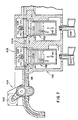
- a guide housing 40 is provided, as shown in Figure 4, for receiving blade 10 and for bending it about radius R, preferably to form an approximate right-angle bend.
- Housing 40 also houses drive means 30. More specifically, upper portion 42 and lower portion 44 of housing 40 provide opposed wall surfaces, such as surfaces 46 and 48, which form a closed curved path 50 of radius R. Blade 10 reciprocates along this path, as shown, in response to the driving action of pinion 32.
- Housing 42 is shaped to accommodate pinion gear 32. The portion 52 of upper housing portion 42 which extends beyond gear 32 towards the rest of the analyzer is linear since it receives the stiff end 12 of blade 10 which will not bend.
- the bend provided by radius R can be some angle considerably different from 90°, for example 30° or 60°.
- An approximate 90° bend is preferred, however, to curl the extension 14 of the blade 10 downwards (as shown in Figure 4), thus minimizing the horizontal extension of the apparatus containing the blade 10.
- stacks 60, 62 ( Figure 4) of test elements E and E′ are disposed adjacent housing portion 52. These stacks 60, 62 are to be operated upon by the pusher blade 10. Test elements E or E′ can be ejected by blade 10 from either stack 60, 62 in the direction indicated by arrow 64, and transferred to other locations, such as a preheater platform 66 adjacent to an incubator 68. Any mechanism for positioning such stacks 60, 62 adjacent to housing portion 52 can be used, as well as any mechanism for raising and lowering the stacks (as indicated by arrows 70, 72) to intersect the path of arrow 64.
- such stacks can be disposed in cartridges 74 and 75 mounted in concentric rings on a rotor 76.
- Such rings can be connected to rotate together, as shown, or they can be independently mounted to rotate separately (not shown).
- Rotor 76 seals at bearing surfaces 78 against a stationary bridging member 80, and is driven by a suitable mechanism, (not shown) preferably attached at wall 82.
- the rotor 76 rotates about an axis of rotation which is to the right or left of the stacks shown in Figure 4. If it is to the right, the axis is preferably centered on incubator 68.
- a plunger 86 is provided at a station adjacent to blade housing 40a, associated with each of the two rings which rotate above the plungers 86.
- the plungers 86 are activated by a mechanism such as is shown in US-A-4512952, to move up and down, in the direction indicated by arrow 90, into and out of aperture 92 of a cartridge 74, 75, to push against the follower element 94 used to prevent remaining elements E or E′ from falling to the bottom of the cartridge 74, 75.
- Bridging member 80 is constructed to allow blade 10 to bridge over either cartridge 74 or 75 (whichever one is not dispensing a test element).
- a shuttle 100 is mounted above the position occupied by cartridge 74, and a separate shuttle 102 above the position occupied by cartridge 75, when either cartridge is otherwise in position to dispense a test element.
- Each shuttle 100, 102 comprises a bottom plate 104, a top plate 106 spaced from the bottom plate a distance d which will accommodate blade 10 and a test element E, E′.
- a pair of compression springs 108 hangs each shuttle 100, 102 from upper surface 110, and a centering rod 112 which slides up and down in aperture 114 in surface 110.
- Springs 108 can be coil springs or leaf springs.
- a spring-biased sealing member 120 is provided between the shuttles 100, 102 to allow separate environments to be provided for the two rings. This is particularly the case if each ring of stacks is separately rotatable. Member 120 is tapered at 122 to allow a pushed test element and blade 10 to cam it upward, as shown in Figure 6.
- the bridging member 80 works by having a cartridge from which a test element is to be ejected, push its associated shuttle (shuttle 100 is pushed up by a cartridge 74 in this Figure) out of the way against spring 108, while the other shuttle (102 here) remains in place to bridge over the space under which cartridge 75 are located. Blade 10 is thus able to pass over both sets of rings of cartridges 74, 75, and through cartridge 74, to eject element E towards preheater platform 66, in the direction of arrow 130. Alternatively, only a cartridge 75 can be elevated against its shuttle 102, and blade 10 pushed, through shuttle 100 and into cartridge 75, in the direction of arrow 132, to eject an element E′.
- a pinch roller 140 can be included in housing portion 44a, mounted opposite to the pinion gear 32a mounted in housing portion 42a of housing 40a.
- motor 36a is offset from drive shaft 34a and connected thereto by drive belt 149.
- housing 40B has a pusher blade 10B driven by motor 36B, and either cartridge 74B or 75B is elevated, in the direction shown by arrows 140, by plungers 86B, as before, into the path 132B of the blade 10B.
- Rotor 76B allows two rows of cartridges to be rotated into the position shown in Figure 7; and wall 77B keeps the two rows of cartridges separate.
- Bridging member 80B covers the cartridges and provides the bridging means for path 132B, generally as before.
- Displaceable shuttle members 100B and 102B allow a cartridge to be inserted into path 132B, or alternatively act as the guide for blade 10B, shuttle 102B, and also for a test element E.
- member 80B is provided with apertures 150 into which a cartridge 74B, 75B is insertable by plunger 86B.
- Each aperture 150 has a sealing seat 152 surrounding it which mates with the annular undersurface 154 of either shuttle 100B or 102B when the shuttle is in the "down" position, as shown.
- Springs 108B bias shuttle members 100B and 102B downwardly, as before, to seal on seats 152.
- blade 10C is housed in housing 40C and driven by driving means 30C as before, with all but end12C of the blade being flexible.
- blade 10C follows a curved path 50C as previously described.
- the back-up member includes a clutch 200, which releases its pressure pushing blade 10C into contact with pinion gear 32C, in the event a jam occurs at end 12C.
- clutch 200 is preferably a spring 202, such as a leaf spring under compression, with a projecting portion 204 which pushes blade 10C against pinion gear 32C with sufficient force to normally keep the blade engaged.
- a useful example of the force of spring portion 204 is about 6.7N (1.51bf). This leaves portion 204 spaced distance d1 from its housing.
- Clutch 200 functions as follows (with reference to Figure 9): If a jam occurs so that a resistant force F in excess of the spring force, e.g., 6.7N (1.51bf) occurs, then spring 202 buckles sufficiently to reduce distance d1 to d2, allowing the flexible blade 10C to itself buckle a sufficient distance as to disengage ribs 26C from pinion gear 32C. As a result, pinion gear 32C can continue to turn without permanently bending blade 10C or breaking off any of the ribs on the blade or the teeth on pinion gear 32C.
Landscapes
- Immunology (AREA)
- Pathology (AREA)
- Life Sciences & Earth Sciences (AREA)
- Chemical & Material Sciences (AREA)
- Analytical Chemistry (AREA)
- Biochemistry (AREA)
- Health & Medical Sciences (AREA)
- General Health & Medical Sciences (AREA)
- Physics & Mathematics (AREA)
- General Physics & Mathematics (AREA)
- Engineering & Computer Science (AREA)
- Mechanical Engineering (AREA)
- Automatic Analysis And Handling Materials Therefor (AREA)
- Investigating Or Analysing Materials By The Use Of Chemical Reactions (AREA)
- Sampling And Sample Adjustment (AREA)
- Paper (AREA)
Applications Claiming Priority (4)
| Application Number | Priority Date | Filing Date | Title |
|---|---|---|---|
| US34945189A | 1989-05-09 | 1989-05-09 | |
| US349451 | 1989-05-09 | ||
| US50065090A | 1990-03-28 | 1990-03-28 | |
| US500650 | 1990-03-28 |
Publications (3)
| Publication Number | Publication Date |
|---|---|
| EP0397255A2 true EP0397255A2 (fr) | 1990-11-14 |
| EP0397255A3 EP0397255A3 (fr) | 1991-07-03 |
| EP0397255B1 EP0397255B1 (fr) | 1994-12-14 |
Family
ID=26996184
Family Applications (1)
| Application Number | Title | Priority Date | Filing Date |
|---|---|---|---|
| EP90201132A Expired - Lifetime EP0397255B1 (fr) | 1989-05-09 | 1990-05-04 | Lame poussoir flexible, et son boîtier |
Country Status (6)
| Country | Link |
|---|---|
| US (1) | US5330716A (fr) |
| EP (1) | EP0397255B1 (fr) |
| JP (1) | JPH0363572A (fr) |
| KR (1) | KR0168660B1 (fr) |
| CA (1) | CA2015910C (fr) |
| DE (1) | DE69014980T2 (fr) |
Cited By (2)
| Publication number | Priority date | Publication date | Assignee | Title |
|---|---|---|---|---|
| WO1992014550A1 (fr) * | 1991-02-14 | 1992-09-03 | Pb Diagnostic Systems, Inc. | Obturation d'orifice d'incubateur pour systeme d'analyse automatique |
| WO2006000792A1 (fr) * | 2004-06-28 | 2006-01-05 | Lifescan Scotland Limited | Appareil et procede automatise motorise permettant de distribuer des bandes d'essai |
Families Citing this family (6)
| Publication number | Priority date | Publication date | Assignee | Title |
|---|---|---|---|---|
| EP0634658B1 (fr) * | 1993-07-16 | 2002-10-16 | Fuji Photo Film Co., Ltd. | Appareil d'analyses biochimiques avec incubateur |
| US5759010A (en) * | 1995-11-06 | 1998-06-02 | Jacobs; Merrit Nyles | Sealed cartridge to improve chemistry stability of test elements |
| JP4742400B2 (ja) * | 1999-10-01 | 2011-08-10 | パナソニック株式会社 | プッシャおよびローダ |
| US20040230400A1 (en) * | 2003-05-13 | 2004-11-18 | Tomasso David Angelo | Analyzer having concentric rotors |
| US8262991B2 (en) | 2003-05-19 | 2012-09-11 | Lattec I/S | Apparatus for analysing fluid taken from a body |
| MXPA06014780A (es) * | 2004-06-24 | 2007-03-23 | Bayer Healthcare Llc | Cartucho e instrumento de distribucion de sensor. |
Family Cites Families (12)
| Publication number | Priority date | Publication date | Assignee | Title |
|---|---|---|---|---|
| DE1250160B (fr) * | 1960-10-10 | |||
| FR1297285A (fr) * | 1961-05-18 | 1962-06-29 | Ct D Etudes Et D Applic Des Te | Dispositif de transmission |
| FR2419244A1 (fr) * | 1978-03-10 | 1979-10-05 | Sidetel | Ejecteur pour la manutention de charges rigides |
| US4303611A (en) * | 1980-08-11 | 1981-12-01 | Eastman Kodak Company | Analyzer apparatus featuring a simplified incubator |
| DE3136335A1 (de) * | 1981-09-14 | 1983-04-14 | Repa Feinstanzwerk Gmbh, 7071 Alfdorf | Antriebsvorrichtung zum bewegen des endbeschlages eines passiv-sicherheitsgurtes |
| US4424191A (en) * | 1982-03-04 | 1984-01-03 | Eastman Kodak Company | Analyzer featuring loading and unloading means for a storage chamber, and common drive means |
| US4512952A (en) * | 1982-07-01 | 1985-04-23 | Eastman Kodak Company | Apparatus for storing and dispensing analysis slides |
| DE3338511A1 (de) * | 1983-10-22 | 1985-05-02 | Robert Bosch Gmbh, 7000 Stuttgart | Durch einen elektromotor ein- oder ausfahrbare teleskopantenne |
| US4649398A (en) * | 1984-01-25 | 1987-03-10 | Nippondenso Co., Ltd. | Motor driven extensible rod antenna for vehicles with position control circuit |
| IT206967Z2 (it) * | 1986-02-11 | 1987-10-26 | Mauri Stefania | Organo continuo atto all'impiego quale trasmissione meccanica bidirezionale di potenza. |
| ATE63385T1 (de) * | 1986-03-26 | 1991-05-15 | Siemens Ag | Halterung einer magnetfeldsonde fuer navigationszwecke an einem kraftfahrzeug. |
| JPH02184761A (ja) * | 1989-01-11 | 1990-07-19 | Fuji Photo Film Co Ltd | スライド供給装置 |
-
1990
- 1990-05-02 CA CA002015910A patent/CA2015910C/fr not_active Expired - Fee Related
- 1990-05-04 EP EP90201132A patent/EP0397255B1/fr not_active Expired - Lifetime
- 1990-05-04 DE DE69014980T patent/DE69014980T2/de not_active Expired - Fee Related
- 1990-05-08 JP JP2117012A patent/JPH0363572A/ja active Pending
- 1990-05-09 KR KR1019900006523A patent/KR0168660B1/ko not_active Expired - Fee Related
- 1990-09-28 US US07/590,205 patent/US5330716A/en not_active Expired - Fee Related
Cited By (3)
| Publication number | Priority date | Publication date | Assignee | Title |
|---|---|---|---|---|
| WO1992014550A1 (fr) * | 1991-02-14 | 1992-09-03 | Pb Diagnostic Systems, Inc. | Obturation d'orifice d'incubateur pour systeme d'analyse automatique |
| AU644278B2 (en) * | 1991-02-14 | 1993-12-02 | Behring Diagnostics Inc. | Incubator port closure for automated assay system |
| WO2006000792A1 (fr) * | 2004-06-28 | 2006-01-05 | Lifescan Scotland Limited | Appareil et procede automatise motorise permettant de distribuer des bandes d'essai |
Also Published As
| Publication number | Publication date |
|---|---|
| CA2015910C (fr) | 1995-01-03 |
| CA2015910A1 (fr) | 1990-11-09 |
| KR900018681A (ko) | 1990-12-22 |
| KR0168660B1 (ko) | 1999-05-01 |
| JPH0363572A (ja) | 1991-03-19 |
| DE69014980D1 (de) | 1995-01-26 |
| US5330716A (en) | 1994-07-19 |
| EP0397255B1 (fr) | 1994-12-14 |
| EP0397255A3 (fr) | 1991-07-03 |
| DE69014980T2 (de) | 1995-08-10 |
Similar Documents
| Publication | Publication Date | Title |
|---|---|---|
| IE901684A1 (en) | Flexible pusher blade and housing | |
| CN211561815U (zh) | 麻将机及其叠推装置 | |
| EP0397255B1 (fr) | Lame poussoir flexible, et son boîtier | |
| US5676910A (en) | Automatic blood film preparation device | |
| KR0163346B1 (ko) | 자동 카세트 체인저 | |
| EP0083649B1 (fr) | Distributeur de comprimes | |
| EP0088601A1 (fr) | Appareil d'analyse pour l'analyse chimique d'un liquide | |
| CN101134534A (zh) | 卡片送出装置 | |
| EP1201576A2 (fr) | Dispositif d'alimentation en feuilles et appareil d'enregistrement muni de ce dispositif | |
| US6814257B2 (en) | Delivery device for cassettes and/or specimen slides for histological preparations in a printing system | |
| US20030180128A1 (en) | Device and methods for automating transfer of multiple samples to an anlytical instrument | |
| EP0405769B1 (fr) | Echange non surveillé de traceur pour appareil d'enregistrement | |
| US4582407A (en) | Automatic distributor for flat rigid pieces | |
| CN114249105A (zh) | 卸料装置 | |
| EP0371027B1 (fr) | Dispositif d'extraction de film en feuille | |
| US5593152A (en) | Sheet media supply tray orients sheets to registration posts in imaging apparatus | |
| CN216582984U (zh) | 样本篮运送系统 | |
| JPH0811476B2 (ja) | シートの束の循環再配列装置 | |
| EP0314089B1 (fr) | Dispositif pour déplacer dans une filature une rangée d'éléments porteurs en forme de disque et d'une cheville placée au centre de celui-ci | |
| KR940003287B1 (ko) | 쉬이트 격납장치 | |
| CN110652720B (zh) | 麻将机及其拾牌搬运系统、叠推装置 | |
| JPH0629818Y2 (ja) | カセツトオ−トチエンジヤ− | |
| JP2746731B2 (ja) | カード繰出し装置 | |
| US4330980A (en) | Apparatus and method for inserting strips of microfilm into microfilm jackets | |
| JPH0679934B2 (ja) | 容器の自動移送装置 |
Legal Events
| Date | Code | Title | Description |
|---|---|---|---|
| PUAI | Public reference made under article 153(3) epc to a published international application that has entered the european phase |
Free format text: ORIGINAL CODE: 0009012 |
|
| AK | Designated contracting states |
Kind code of ref document: A2 Designated state(s): BE CH DE FR GB IT LI LU NL |
|
| PUAL | Search report despatched |
Free format text: ORIGINAL CODE: 0009013 |
|
| AK | Designated contracting states |
Kind code of ref document: A3 Designated state(s): BE CH DE FR GB IT LI LU NL |
|
| 17P | Request for examination filed |
Effective date: 19911204 |
|
| 17Q | First examination report despatched |
Effective date: 19931116 |
|
| GRAA | (expected) grant |
Free format text: ORIGINAL CODE: 0009210 |
|
| ITF | It: translation for a ep patent filed | ||
| AK | Designated contracting states |
Kind code of ref document: B1 Designated state(s): BE CH DE FR GB IT LI LU NL |
|
| PG25 | Lapsed in a contracting state [announced via postgrant information from national office to epo] |
Ref country code: NL Effective date: 19941214 Ref country code: LI Effective date: 19941214 Ref country code: CH Effective date: 19941214 Ref country code: BE Effective date: 19941214 |
|
| REF | Corresponds to: |
Ref document number: 69014980 Country of ref document: DE Date of ref document: 19950126 |
|
| ET | Fr: translation filed | ||
| REG | Reference to a national code |
Ref country code: CH Ref legal event code: PL |
|
| NLV1 | Nl: lapsed or annulled due to failure to fulfill the requirements of art. 29p and 29m of the patents act | ||
| PG25 | Lapsed in a contracting state [announced via postgrant information from national office to epo] |
Ref country code: LU Free format text: LAPSE BECAUSE OF NON-PAYMENT OF DUE FEES Effective date: 19950531 |
|
| RAP2 | Party data changed (patent owner data changed or rights of a patent transferred) |
Owner name: CLINICAL DIAGNOSTIC SYSTEMS, INC. |
|
| RAP2 | Party data changed (patent owner data changed or rights of a patent transferred) |
Owner name: JOHNSON & JOHNSON CLINICAL DIAGNOSTICS, INC. |
|
| PLBE | No opposition filed within time limit |
Free format text: ORIGINAL CODE: 0009261 |
|
| STAA | Information on the status of an ep patent application or granted ep patent |
Free format text: STATUS: NO OPPOSITION FILED WITHIN TIME LIMIT |
|
| 26N | No opposition filed | ||
| REG | Reference to a national code |
Ref country code: GB Ref legal event code: 732E |
|
| PGFP | Annual fee paid to national office [announced via postgrant information from national office to epo] |
Ref country code: DE Payment date: 20010430 Year of fee payment: 12 |
|
| PGFP | Annual fee paid to national office [announced via postgrant information from national office to epo] |
Ref country code: GB Payment date: 20010502 Year of fee payment: 12 |
|
| PGFP | Annual fee paid to national office [announced via postgrant information from national office to epo] |
Ref country code: FR Payment date: 20010518 Year of fee payment: 12 |
|
| REG | Reference to a national code |
Ref country code: GB Ref legal event code: IF02 |
|
| PG25 | Lapsed in a contracting state [announced via postgrant information from national office to epo] |
Ref country code: GB Free format text: LAPSE BECAUSE OF NON-PAYMENT OF DUE FEES Effective date: 20020504 |
|
| PG25 | Lapsed in a contracting state [announced via postgrant information from national office to epo] |
Ref country code: DE Free format text: LAPSE BECAUSE OF NON-PAYMENT OF DUE FEES Effective date: 20021203 |
|
| GBPC | Gb: european patent ceased through non-payment of renewal fee |
Effective date: 20020504 |
|
| PG25 | Lapsed in a contracting state [announced via postgrant information from national office to epo] |
Ref country code: FR Free format text: LAPSE BECAUSE OF NON-PAYMENT OF DUE FEES Effective date: 20030131 |
|
| REG | Reference to a national code |
Ref country code: FR Ref legal event code: ST |
|
| PG25 | Lapsed in a contracting state [announced via postgrant information from national office to epo] |
Ref country code: IT Free format text: LAPSE BECAUSE OF NON-PAYMENT OF DUE FEES;WARNING: LAPSES OF ITALIAN PATENTS WITH EFFECTIVE DATE BEFORE 2007 MAY HAVE OCCURRED AT ANY TIME BEFORE 2007. THE CORRECT EFFECTIVE DATE MAY BE DIFFERENT FROM THE ONE RECORDED. Effective date: 20050504 |