EP0397954A2 - Fördervorrichtung für Maschinen oder Werkzeuge, die entlang kontinuierlichen Produktionslinien eingesetzt sind,insbesondere für Eisen- und Stahlproduktionslinien - Google Patents
Fördervorrichtung für Maschinen oder Werkzeuge, die entlang kontinuierlichen Produktionslinien eingesetzt sind,insbesondere für Eisen- und Stahlproduktionslinien Download PDFInfo
- Publication number
- EP0397954A2 EP0397954A2 EP89830460A EP89830460A EP0397954A2 EP 0397954 A2 EP0397954 A2 EP 0397954A2 EP 89830460 A EP89830460 A EP 89830460A EP 89830460 A EP89830460 A EP 89830460A EP 0397954 A2 EP0397954 A2 EP 0397954A2
- Authority
- EP
- European Patent Office
- Prior art keywords
- pulleys
- production lines
- mobile assembly
- base
- drums
- Prior art date
- Legal status (The legal status is an assumption and is not a legal conclusion. Google has not performed a legal analysis and makes no representation as to the accuracy of the status listed.)
- Withdrawn
Links
Images

Classifications
-
- B—PERFORMING OPERATIONS; TRANSPORTING
- B23—MACHINE TOOLS; METAL-WORKING NOT OTHERWISE PROVIDED FOR
- B23D—PLANING; SLOTTING; SHEARING; BROACHING; SAWING; FILING; SCRAPING; LIKE OPERATIONS FOR WORKING METAL BY REMOVING MATERIAL, NOT OTHERWISE PROVIDED FOR
- B23D45/00—Sawing machines or sawing devices with circular saw blades or with friction saw discs
- B23D45/18—Machines with circular saw blades for sawing stock while the latter is travelling otherwise than in the direction of the cut
-
- B—PERFORMING OPERATIONS; TRANSPORTING
- B23—MACHINE TOOLS; METAL-WORKING NOT OTHERWISE PROVIDED FOR
- B23Q—DETAILS, COMPONENTS, OR ACCESSORIES FOR MACHINE TOOLS, e.g. ARRANGEMENTS FOR COPYING OR CONTROLLING; MACHINE TOOLS IN GENERAL CHARACTERISED BY THE CONSTRUCTION OF PARTICULAR DETAILS OR COMPONENTS; COMBINATIONS OR ASSOCIATIONS OF METAL-WORKING MACHINES, NOT DIRECTED TO A PARTICULAR RESULT
- B23Q1/00—Members which are comprised in the general build-up of a form of machine, particularly relatively large fixed members
- B23Q1/25—Movable or adjustable work or tool supports
- B23Q1/44—Movable or adjustable work or tool supports using particular mechanisms
- B23Q1/56—Movable or adjustable work or tool supports using particular mechanisms with sliding pairs only, the sliding pairs being the first two elements of the mechanism
- B23Q1/58—Movable or adjustable work or tool supports using particular mechanisms with sliding pairs only, the sliding pairs being the first two elements of the mechanism a single sliding pair
-
- B—PERFORMING OPERATIONS; TRANSPORTING
- B23—MACHINE TOOLS; METAL-WORKING NOT OTHERWISE PROVIDED FOR
- B23Q—DETAILS, COMPONENTS, OR ACCESSORIES FOR MACHINE TOOLS, e.g. ARRANGEMENTS FOR COPYING OR CONTROLLING; MACHINE TOOLS IN GENERAL CHARACTERISED BY THE CONSTRUCTION OF PARTICULAR DETAILS OR COMPONENTS; COMBINATIONS OR ASSOCIATIONS OF METAL-WORKING MACHINES, NOT DIRECTED TO A PARTICULAR RESULT
- B23Q5/00—Driving or feeding mechanisms; Control arrangements therefor
- B23Q5/22—Feeding members carrying tools or work
- B23Q5/34—Feeding other members supporting tools or work, e.g. saddles, tool-slides, through mechanical transmission
-
- B—PERFORMING OPERATIONS; TRANSPORTING
- B23—MACHINE TOOLS; METAL-WORKING NOT OTHERWISE PROVIDED FOR
- B23Q—DETAILS, COMPONENTS, OR ACCESSORIES FOR MACHINE TOOLS, e.g. ARRANGEMENTS FOR COPYING OR CONTROLLING; MACHINE TOOLS IN GENERAL CHARACTERISED BY THE CONSTRUCTION OF PARTICULAR DETAILS OR COMPONENTS; COMBINATIONS OR ASSOCIATIONS OF METAL-WORKING MACHINES, NOT DIRECTED TO A PARTICULAR RESULT
- B23Q7/00—Arrangements for handling work specially combined with or arranged in, or specially adapted for use in connection with, machine tools, e.g. for conveying, loading, positioning, discharging, sorting
- B23Q7/007—Flying working devices
-
- Y—GENERAL TAGGING OF NEW TECHNOLOGICAL DEVELOPMENTS; GENERAL TAGGING OF CROSS-SECTIONAL TECHNOLOGIES SPANNING OVER SEVERAL SECTIONS OF THE IPC; TECHNICAL SUBJECTS COVERED BY FORMER USPC CROSS-REFERENCE ART COLLECTIONS [XRACs] AND DIGESTS
- Y10—TECHNICAL SUBJECTS COVERED BY FORMER USPC
- Y10T—TECHNICAL SUBJECTS COVERED BY FORMER US CLASSIFICATION
- Y10T74/00—Machine element or mechanism
- Y10T74/18—Mechanical movements
- Y10T74/18568—Reciprocating or oscillating to or from alternating rotary
- Y10T74/18832—Reciprocating or oscillating to or from alternating rotary including flexible drive connector [e.g., belt, chain, strand, etc.]
- Y10T74/18848—Reciprocating or oscillating to or from alternating rotary including flexible drive connector [e.g., belt, chain, strand, etc.] with pulley
-
- Y—GENERAL TAGGING OF NEW TECHNOLOGICAL DEVELOPMENTS; GENERAL TAGGING OF CROSS-SECTIONAL TECHNOLOGIES SPANNING OVER SEVERAL SECTIONS OF THE IPC; TECHNICAL SUBJECTS COVERED BY FORMER USPC CROSS-REFERENCE ART COLLECTIONS [XRACs] AND DIGESTS
- Y10—TECHNICAL SUBJECTS COVERED BY FORMER USPC
- Y10T—TECHNICAL SUBJECTS COVERED BY FORMER US CLASSIFICATION
- Y10T74/00—Machine element or mechanism
- Y10T74/20—Control lever and linkage systems
- Y10T74/20396—Hand operated
- Y10T74/20402—Flexible transmitter [e.g., Bowden cable]
- Y10T74/20408—Constant tension sustaining
- Y10T74/20414—Hydraulic control
Definitions
- the invention relates to a propulsion device for power machines or tools stationed along continuous flow production lines, in particular as adopted in the manufacture of iron and steel products.
- Such devices serve specifically, though by no means exclusively, to generate the following movement of 'flying' machine units or equipment used to effect operations such as shearing, cross-cutting and punching, etc., on part-machined work generally, which cannot be allowed to remain stationary in a fixed position due to its very nature or shape, or to the operating requirements of production media installed up-line, but must be kept moving steadily forward (generally along a straight path).
- Devices of the type in question operate to a set cycle that must be completed normally within a significantly short space of time, and will include a succession of essential steps: 1) hard acceleration, serving to take the machine or equipment at high speed from a stationary at-rest position up to a velocity approaching that of the work moving along the line; 2) stabilization and alignment, whereby the machine or equipment gains a velocity identical to that of the line and the tool is positioned accurately in readiness to operate; 3) operation of the machine or equipment proper, following the moving line at identical velocity for as long as is necessary to effect the machining stroke and retract the tool; 4) hard deceleration, whereby the machine is slowed up to a complete standstill at the installed travel limit; 5) return of the machine or equipment to the original at-rest position in readiness for the next cycle.
- conventional propulsion devices which utilize clutch-brake mechanisms combine positive features such as accuracy in synchronization, i.e. obtaining identical velocity of the tool and the work, with negative factors such as poor alignment and heavy wear, which severely jeopardizes the dependability of the clutch and brake assemblies.
- Other conventional propulsion devices utilize fluid power, hydraulic or pneumatic. Whilst the actuator is essentially simple in such devices (an ordinary cylinder), synchronization between the velocities of tool and work nonetheless require complicated mechanisms, and the fluid control systems tend to be low on dependability due to the hostility of the operating environment.
- the prior art embraces electromechanical systems utilizing a geared electric motor coupled to a rack-and-pinion type drive, which apparently possess all the features necessary for faultless implementation of the propulsion cycle in question (fine adjustment of drive parameters, good levels of machining accuracy, good general flexibility), though in practice, serious limitations are found to exist precisely in iron and steel manufacture; more exactly, the rack-and-pinion drive, essential to ensuring a rigid connection between the geared motor and the moving assembly, becomes subject to early wear as a result of operating in environments that are heavily laden with oxides, hemimorphites and swarf.
- the object of the present invention is to overcome the various drawbacks and shortcomings of the prior art as described above.
- the stated object is realized with a propulsion device that permits of controlling movement and accuracy parameters, and at the same time, of eliminating almost all those problems connected with mechanical parts wear that are attributable to hostile operating environments.
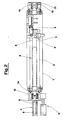
- 1 denotes a bed, in its entirety, provided uppermost with rectilinear ways 2 on which a mobile assembly denoted 3 is slidably mounted.
- the ways 2 are disposed parallel to a production line 4 carrying items fashioned in steel, or metal generally, in a continuous and uniform stream.
- the mobile assembly 3 comprises a power machine 5 the purpose of which is to effect an operation on each part-finished item of work 6 at a prescribed juncture, without interrupting the continuous movement of the work along the line 4.
- the mobile assembly 3 is supported by a frame 7 provided with guide elements that enable it to travel slidably along the ways 2 in one direction and the other, and connected permanently to a pair of ropes 8, for example wire, disposed parallel with one another and looped tautly around relative pairs of pulleys 9 and 10, the degree of tautness being sufficient to ensure a suitable measure of grip between pulleys and rope; in the embodiment illustrated, the frame 7 is made fast to the top branch of each loop 8.
- the pulleys denoted 9 are coaxial, and mounted to a common shaft coupled directly to a geared motor 11, thus functioning as driving members.
- the pulleys 9 and geared motor 11 are mounted to an adjustable base 12 capable of movement at least in a direction parallel to the ways 2 and associated with the main bed 1 by way of a pair of hydraulic actuators 14.
- the remaining pulleys 10 are freely revolving and mounted to a fixed base 13.
- the purpose of the actuators 14 is to set and hold the ropes 8 at a prescribed tension, whilst the geared motor 11 serves to transmit drive to the mobile assembly 3 by way of the ropes 8, and to control its following movement.
- live pulleys could be used at both ends of each loop.
Landscapes
- Engineering & Computer Science (AREA)
- Mechanical Engineering (AREA)
- Transmission Devices (AREA)
- Shearing Machines (AREA)
- Metal Extraction Processes (AREA)
Applications Claiming Priority (2)
| Application Number | Priority Date | Filing Date | Title |
|---|---|---|---|
| IT8940081A IT1233340B (it) | 1989-05-17 | 1989-05-17 | Dispositivo di lancio per macchine operatrici o attrezzi operanti su linee a flusso continuo in particolare per la fabbricazione di prodotti siderurgici |
| IT4008189 | 1989-05-17 |
Publications (2)
| Publication Number | Publication Date |
|---|---|
| EP0397954A2 true EP0397954A2 (de) | 1990-11-22 |
| EP0397954A3 EP0397954A3 (de) | 1991-04-03 |
Family
ID=11247778
Family Applications (1)
| Application Number | Title | Priority Date | Filing Date |
|---|---|---|---|
| EP19890830460 Withdrawn EP0397954A3 (de) | 1989-05-17 | 1989-10-24 | Fördervorrichtung für Maschinen oder Werkzeuge, die entlang kontinuierlichen Produktionslinien eingesetzt sind,insbesondere für Eisen- und Stahlproduktionslinien |
Country Status (4)
| Country | Link |
|---|---|
| US (1) | US5157980A (de) |
| EP (1) | EP0397954A3 (de) |
| JP (1) | JPH02303709A (de) |
| IT (1) | IT1233340B (de) |
Families Citing this family (6)
| Publication number | Priority date | Publication date | Assignee | Title |
|---|---|---|---|---|
| US7594912B2 (en) | 2004-09-30 | 2009-09-29 | Intuitive Surgical, Inc. | Offset remote center manipulator for robotic surgery |
| US10646292B2 (en) | 2004-09-30 | 2020-05-12 | Intuitive Surgical Operations, Inc. | Electro-mechanical strap stack in robotic arms |
| US9261172B2 (en) * | 2004-09-30 | 2016-02-16 | Intuitive Surgical Operations, Inc. | Multi-ply strap drive trains for surgical robotic arms |
| CN103802129B (zh) * | 2012-11-08 | 2016-04-20 | 深圳市艾而特工业自动化设备有限公司 | 精准定位高速机械臂 |
| CN108145506B (zh) * | 2017-12-27 | 2020-07-10 | 绍兴市尊铖自动化设备有限公司 | 一种用于自动切割机的输送计量装置 |
| CN111730396B (zh) * | 2020-06-28 | 2021-09-17 | 宁夏隆基宁光仪表股份有限公司 | 一种机械加工用夹取装置 |
Family Cites Families (17)
| Publication number | Priority date | Publication date | Assignee | Title |
|---|---|---|---|---|
| US683968A (en) * | 1900-10-26 | 1901-10-08 | James H Young | Driving connection for motors. |
| US2341870A (en) * | 1941-11-15 | 1944-02-15 | Mckay Machine Co | Automatic cutoff |
| US2666863A (en) * | 1951-03-08 | 1954-01-19 | Prosperity Co Inc | Two electric motor power unit |
| US2788883A (en) * | 1954-02-01 | 1957-04-16 | Bernard E Schwenk | Belt adjuster |
| DE1861809U (de) * | 1962-08-31 | 1962-11-08 | Kieserling & Albrecht | Vorrichtung zum unterteilen eines in bewegung befindlichen trenngutes, beispielsweise ein rohrwalzwerk verlassenden rohrstranges in bestimmte laengen. |
| AT237413B (de) * | 1963-08-02 | 1964-12-10 | Voest Ag | Ablängvorrichtung für laufendes Stranggut |
| US3283918A (en) * | 1963-12-02 | 1966-11-08 | George C Devol | Coordinated conveyor and programmed apparatus |
| DE1502967C3 (de) * | 1964-06-20 | 1973-12-13 | Schloemann Ag, 4000 Duesseldorf | Mitlaufende Kreissagevorrichtung |
| US3568569A (en) * | 1969-03-05 | 1971-03-09 | Babcock & Wilcox Co | Drives for broaching machines and the like |
| US3659468A (en) * | 1969-12-10 | 1972-05-02 | Andrew Alford | Slotted waveguide carriage movement apparatus |
| FR2429061A1 (fr) * | 1978-06-23 | 1980-01-18 | Pont A Mousson | Machine d'extraction de tuyaux centrifuges |
| JPS5627716A (en) * | 1979-08-08 | 1981-03-18 | Meidensha Electric Mfg Co Ltd | Chain belt type running cutter |
| FR2501563B1 (fr) * | 1981-03-10 | 1986-07-18 | Sormel Sa | Manipulateur automatique |
| US4561624A (en) * | 1983-06-30 | 1985-12-31 | Champion Spark Plug Company | Mounting platform |
| JPS6021125U (ja) * | 1983-07-20 | 1985-02-14 | 三洋電機株式会社 | 照光スイッチ |
| JPS61180698A (ja) * | 1985-02-07 | 1986-08-13 | Nippon Steel Weld Prod & Eng Co Ltd | 被覆溶接棒塗装機のクロスコンベア |
| US4893661A (en) * | 1989-02-22 | 1990-01-16 | C. R. Onsrud, Inc. | Drive belt tension control apparatus for inverted rooter |
-
1989
- 1989-05-17 IT IT8940081A patent/IT1233340B/it active
- 1989-10-24 EP EP19890830460 patent/EP0397954A3/de not_active Withdrawn
- 1989-11-07 JP JP1288072A patent/JPH02303709A/ja active Pending
-
1991
- 1991-08-26 US US07/749,565 patent/US5157980A/en not_active Expired - Lifetime
Also Published As
| Publication number | Publication date |
|---|---|
| US5157980A (en) | 1992-10-27 |
| EP0397954A3 (de) | 1991-04-03 |
| IT8940081A0 (it) | 1989-05-17 |
| JPH02303709A (ja) | 1990-12-17 |
| IT1233340B (it) | 1992-03-27 |
Similar Documents
| Publication | Publication Date | Title |
|---|---|---|
| US4726464A (en) | Carriage with tiltable plates, for sorting machines in particular | |
| EP0548128B1 (de) | System von arbeitsvorrichtungen | |
| JP5287230B2 (ja) | 作業具の移動装置およびローダ装置 | |
| US4666367A (en) | Apparatus for handling a structural part | |
| US5267478A (en) | Device for a rapid positioning of a heavy carriage | |
| US4411182A (en) | Belt driven flying cutoff apparatus | |
| US3448645A (en) | Numerically controlled punching machine and method | |
| EP0467268B1 (de) | Numerisch gesteuertes Gerät sowie ein numerisch gesteuertes Schlitzgerät | |
| KR20160042876A (ko) | 피가공물용 이송 장치 | |
| US5157980A (en) | Propulsion device for power machines or tools operating along continuous flow production lines | |
| JP2726728B2 (ja) | 重量キャリジの高速位置決め用装置 | |
| JP2007237346A (ja) | 搬送用ロボットアーム | |
| JP4489865B2 (ja) | プレス式孔明け用ハンドリング装置 | |
| CN207447620U (zh) | 一种激光切割装置 | |
| KR0144854B1 (ko) | 물건운반용 설비 | |
| US4499794A (en) | Machine for machining circular saw blades | |
| US4548536A (en) | Working apparatus with track following motion | |
| CN207448470U (zh) | 悬吊式热喷涂二维机械手装置 | |
| CN213859652U (zh) | 自动化模切装置 | |
| CN112475214B (zh) | 杠杆切一体机 | |
| CN209936901U (zh) | 快速高精度水平直线运动系统 | |
| EP0150915B1 (de) | Spindelantrieb für Werkzeugmaschine | |
| JPH02145205A (ja) | 形鋼穿孔機 | |
| GB931178A (en) | Wire drawing machine | |
| US4136519A (en) | Hydraulic cycloidal drive |
Legal Events
| Date | Code | Title | Description |
|---|---|---|---|
| PUAI | Public reference made under article 153(3) epc to a published international application that has entered the european phase |
Free format text: ORIGINAL CODE: 0009012 |
|
| AK | Designated contracting states |
Kind code of ref document: A2 Designated state(s): AT BE CH DE ES FR GB GR LI LU NL SE |
|
| PUAL | Search report despatched |
Free format text: ORIGINAL CODE: 0009013 |
|
| RHK1 | Main classification (correction) |
Ipc: B23D 45/20 |
|
| AK | Designated contracting states |
Kind code of ref document: A3 Designated state(s): AT BE CH DE ES FR GB GR LI LU NL SE |
|
| 17P | Request for examination filed |
Effective date: 19910620 |
|
| 17Q | First examination report despatched |
Effective date: 19921218 |
|
| STAA | Information on the status of an ep patent application or granted ep patent |
Free format text: STATUS: THE APPLICATION IS DEEMED TO BE WITHDRAWN |
|
| 18D | Application deemed to be withdrawn |
Effective date: 19930429 |