EP0398006A2 - Feuille de retenue par dépression - Google Patents
Feuille de retenue par dépression Download PDFInfo
- Publication number
- EP0398006A2 EP0398006A2 EP90106339A EP90106339A EP0398006A2 EP 0398006 A2 EP0398006 A2 EP 0398006A2 EP 90106339 A EP90106339 A EP 90106339A EP 90106339 A EP90106339 A EP 90106339A EP 0398006 A2 EP0398006 A2 EP 0398006A2
- Authority
- EP
- European Patent Office
- Prior art keywords
- blanket
- vacuum
- bladder
- seams
- air
- Prior art date
- Legal status (The legal status is an assumption and is not a legal conclusion. Google has not performed a legal analysis and makes no representation as to the accuracy of the status listed.)
- Withdrawn
Links
Images



Classifications
-
- G—PHYSICS
- G03—PHOTOGRAPHY; CINEMATOGRAPHY; ANALOGOUS TECHNIQUES USING WAVES OTHER THAN OPTICAL WAVES; ELECTROGRAPHY; HOLOGRAPHY
- G03B—APPARATUS OR ARRANGEMENTS FOR TAKING PHOTOGRAPHS OR FOR PROJECTING OR VIEWING THEM; APPARATUS OR ARRANGEMENTS EMPLOYING ANALOGOUS TECHNIQUES USING WAVES OTHER THAN OPTICAL WAVES; ACCESSORIES THEREFOR
- G03B17/00—Details of cameras or camera bodies; Accessories therefor
- G03B17/56—Accessories
-
- G—PHYSICS
- G03—PHOTOGRAPHY; CINEMATOGRAPHY; ANALOGOUS TECHNIQUES USING WAVES OTHER THAN OPTICAL WAVES; ELECTROGRAPHY; HOLOGRAPHY
- G03B—APPARATUS OR ARRANGEMENTS FOR TAKING PHOTOGRAPHS OR FOR PROJECTING OR VIEWING THEM; APPARATUS OR ARRANGEMENTS EMPLOYING ANALOGOUS TECHNIQUES USING WAVES OTHER THAN OPTICAL WAVES; ACCESSORIES THEREFOR
- G03B27/00—Photographic printing apparatus
- G03B27/02—Exposure apparatus for contact printing
- G03B27/14—Details
- G03B27/18—Maintaining or producing contact pressure between original and light-sensitive material
- G03B27/20—Maintaining or producing contact pressure between original and light-sensitive material by using a vacuum or fluid pressure
Definitions
- the present invention relates to vacuum blankets and more particularly, to vacuum blankets of the type used for holding a pre-sensitized sheet of film material in precise registration with a film master against a flat, transparent, rigid plate for controlled light exposure to form a pattern or image on the pre-sensitized sheet of film.
- German Patent No. 29 28 320 C2 discloses a vacuum blanket having criss-crossed grooves for facilitating air removal from the central portion of the blanket when a vacuum is drawn.
- German Patent No. 31 22 707 A1 discloses a blanket backed up by a mechanical roller system for eliminating entrapped air.
- Maher et al U.S. Patent No. 4,551,016 discloses a vacuum printer wherein a spring biased floating plate is used to back up a flexible blanket and Maher et al Patent No. 4,484,813 discloses a system wherein a perforated rigid plate backs up a flexible blanket.
- Yet another object of the present invention is to provide a new and improved vacuum blanket of the character described which is relatively low in cost, extremely reliable in operation and one which assures a high quality product every time.
- Still another object of the present invention is to provide a new and improved vacuum blanket of the character described which uses both a vacuum principle for assuring precise film master registration along with positively pressurized air chambers for assisting in the rapid removal of any air entrapped between confronting faces of the film materials involved.
- Another object of the present invention is to provide a new and improved vacuum blanket of the character described wherein a plurality of interiorly positioned induced bleed passages are formed momentarily when the vacuumizing process is initiated to insure that all of the air is rapidly removed from between confronting faces of the film sheets, thereby producing a high quality registration between a film master and a pre-sensitized copy sheet.
- the foregoing and other objects and advantages of the present invention are accomplished in a preferred embodiment described herein comprising a new and improved vacuum blanket for holding a pre-sensitized film medium in precise registration with a film master against a transparent, glass or plastic, rigid exposure plate.
- the vacuum blanket includes an inner sheet or blanket of thin, flexible sheet material having at least one vacuum port therein and an inside face opposing the rigid exposure plate and adapted for biasing the pre-sensitized film sheet and the master image film sheet toward the rigid plate when a vacuum is induced by withdrawing air through the vacuum port.
- a flexible perimeter seal is provided around the edge of the inner blanket for sealing off a vacuum chamber between the blanket and the rigid plate when air is withdrawn through the vacuum port.
- a bladder of thin, flexible sheet material is attached to an outer surface of the blanket along spaced apart, parallel seams forming a plurality of separate, inflatable air chambers on the outside of the inner blanket.
- At least one inflation port is provided in the bladder for directing pressurized air to inflate the air chambers and thereby create a plurality of induced bleed passages which are momentarily formed along the seams of attachment by a slight movement of the inner blanket and the film sheets away from the planar surface of the rigid exposure plate.
- This pulling away action of the inner blanket sheet forms a plurality of parallel interior passageways for rapidly evacuating the vacuum chamber or space defined between the film sheets and the rigid plate when air is withdrawn by a vacuum pump.
- pressurized air is introduced into the plurality of inflatable air chambers on the outer or back side of the inner blanket and this action assists the evacuation process in the vacuum chamber momentarily by establishing the plurality of induced bleed passages along the seams between the film sheets and the inner blanket and rigid exposure plate.
- the inflatable air chambers are also evacuated and atmospheric air pressure is effective to bias both the bladder sheet and the inner blanket of flexible material toward the rigid exposure plate while the copying process takes place.
- the vacuum chamber between the inner blanket and rigid plate is again filled with atmospheric air pressure to release the peripheral seal and the film sheets are then readily removed from the space between the inner blanket sheet and the rigid exposure plate.
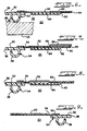
- a new and improved vacuum blanket 20 constructed in accordance with the features of the present invention and especially designed and adapted for use in graphic arts for making images on media such as a thin film of pre-sensitized, flexible, sheet material 24 maintained in close precisely aligned registration with a film image master 22, also of thin flexible sheet material. Exposure of the sheet 24 is obtained by precisely timed exposure to light passing from an external source of light through a rigid plate 26 of glass or transparent plastic having a planar surface 28 as best shown in FIGS. 10, 10a and 10b.
- the vacuum blanket 20 includes an inner layer or blanket 30 formed of thin, flexible, strong, resilient sheet material such as a vinyl or urethane plastic coated woven fabric.
- the vinyl or urethane coated inner blanket 30 is generally rectangular in shape and is dimensioned in accordance with the largest size of media or film sheets 22 and 24 that are to be used.
- the inner blanket 30 is impervious to the passage of air or gas therethrough and has a thickness or weight per square foot, flexibility, resiliency, and strength characteristics to provide for a large number of repetitive operational cycles wherein the blanket is momentarily deflected away from a precise planar configuration and then returned to a precisely flattened or planar condition for positively biasing the master image film sheet 24 and the pre-sensitized film sheet 22 toward the planar surface 28 of the glass plate 26 of a graphic arts plate maker and the like (not shown).
- the vacuum blanket 20 is provided with a peripheral, flexible, vacuum sealing strip 34 having a generally rectangular outline around the peripheral edge of the inner blanket 30.
- the sealing strip 34 has a J-shaped transverse cross-section as shown in FIGS. 6 through 9 and includes a flexible sealing lip 36 adapted to seal tightly against the planar surface 28 of the glass plate 26 as shown in FIG. 6.
- the peripheral sealing strip 34 includes a flat, base portion 38 which is adhesively secured to the inside face of the vinyl or urethane coated inner vacuum blanket 30 as best shown in FIGS. 6 through 9.
- the inner blanket 30 is provided with a plurality of vacuum ports 40 (FIG. 2) located at corner portions as best shown in FIG. 2.
- Each vacuum port 40 is provided with a surrounding vacuum outlet fitting 42 having a circular base 44 adhesively or otherwise sealed and secured to an outside surface of the inner blanket 30.
- the fitting 42 includes a vacuum outlet conduit 46 in direct communication with the hole or port 40 in the flexible vacuum blanket 30.
- the vacuum outlet fittings 42 are formed of integrally molded, resilient plastic material such as rubber or vinyl and the circular bases 44 of the fittings are sealingly secured to the surface of the flexible inner blanket 30 to provide an airtight seal around the associated vacuum port 40.
- a vacuum source such as a vacuum pump 48 is connected to the outlet conduits 46 of the outlet fittings 42 via a flexible conduit 50 (FIG. 11)
- air within the space or vacuum chamber 32 between the flexible blanket 30 and the planar surface 28 of the fixed glass plate 26 is rapidly withdrawn and the vacuum blanket 20 is deflected inwardly toward the surface 28 by virtue of atmospheric pressure acting on the outside surface of the vacuum blanket 20.
- the J-shaped deflectable sealing lip 36 around the periphery of the vacuum blanket 20 is pressed tightly against the planar surface 28 of the glass block 26 to form an airtight seal so that the vacuum chamber 32 is rapidly evacuated when the vacuum pump 48 is running.
- the flexible inner blanket sheet 30 biases the pre-sensitized media film sheet 24 and the film master image sheet 22 tightly against the planar surface 28 to provide a continuous and precise registration between the film master and the media sheet as long as the vacuum is maintained.
- controlled light from an external source such as an arc light of a plate maker or other device is illuminated for a precise period of time and this light as indicated by the arrows A in FIG. 10 passes through the film master sheet 22 to form an image on the pre-sensitized film sheet 24.
- the light source is turned off and the pre-sensitized sheet material 24 has an image formed thereon precisely corresponding to the image present on the film master sheet 22.
- the vacuum blanket 20 includes an outer bladder 52 formed of of thin, flexible, resilient, sheet material comprising a woven fabric covered with vinyl and/or urethane plastic material.
- the bladder sheet 52 has a thickness somewhat less than that of the inner blanket sheet 30 as best shown in FIGS. 10, 10a and 10b, and is secured to an outside face of the inner blanket sheet along a rectangular-shaped outline or perimeter sealing strip 54 (FIG. 1 and 7-9) forming a large, rectangular air pocket on the back side of the inner blanket sheet 30.
- the rectangular, peripheral sealing strip 54 comprises a strip formed by heat sealing such as radio-frequency heat sealing, vulcanizing, and/or adhesive material that is compatible with the vinyl or urethane covering on the woven fabric sheets 30 and 52 to provide a strong, airtight seal.
- heat sealing such as radio-frequency heat sealing, vulcanizing, and/or adhesive material that is compatible with the vinyl or urethane covering on the woven fabric sheets 30 and 52 to provide a strong, airtight seal.
- peripheral sealing strip 54 between the back or outside surface of the inner blanket 30 and the inner face of the bladder sheet 52 there is also formed a plurality of separate, elongated, parallel seams 56 which divide the surface area of the bladder sheet 52 into a plurality of smaller, rectangular-shaped, elongated air pressure chambers 60.
- an outer sheet 62 of thin, flexible, resilient plastic material is secured to the outside surface of the bladder 52 along the outside face of the parallel seams 56 thereby creating a plurality of outer batten pockets 64.
- Each pocket is adapted for containing an elongated, relatively thin stiff batten 66 formed of aluminum or hard plastic material and slipped longitudinally into the pockets 64 from the open ends thereof.
- the outer sheet 62 may also comprise a vinyl or urethane coated woven fabric like the inner blanket 30 and the bladder 52.
- the outer sheet 62 is usually joined to the outside surface of the bladder 52 along the seam areas 56 by heat sealing or adhesives to provide a strong and relatively stiff seam or joint.
- the battens 66 may be formed of a variety of materials such as 1/16" thick aluminum or a relatively stiff, hard plastic material that is generally similar to battens of a sailboat.
- each inlet fitting includes a circular base 72 adhesively or heat sealed to the surface of the bladder 52 around a pressure inlet port 70 and an inlet conduit 74 connected to a flexible pressure line 76 supplied with pressurized air from a pressure pump 78 as shown in the diagram of FIG. 11.
- the relatively rigid battens 66 when inserted into the batten pockets 64 provide stiffness for the outer walls of the pressure chambers 60 so that when the chambers are inflated with air at 3 to 5 psi above atmospheric pressure by the pump 78, the opposite flexible walls of each chamber tends to form a generally symmetrical, transverse cross-section as illustrated in FIGS. 10 and 10a.
- a small portion of the inner vacuum blanket 30 is pulled away from the rigid glass plate 26 along the seam areas 56 thereby forming an induced bleed channel 80 running along the seam to provide a conduit for rapid evacuation of the air within the space or vacuum chamber 32 inside the peripheral seal 34 when the vacuum pump 48 is energized.
- Each induced bleed channel 80 comprises three different portions or segments 80-1, 80-2 and 80-3 and each segment is in parallel with the others forming a set of three along each seam 56 as shown in FIGS. 10 and 10a.
- a first segment 80-1 of each bleed channel set 80 comprises a thin space or area formed between the pre-sensitized film sheet 24 and the planar surface 28 of the rigid glass plate 26 thereby providing a plurality of separate interior pathways for the escape for any air entrapped between these faces of the member when a vacuum is drawn through the ports 40 immediately after the peripheral seal 34 has been established.
- a second segment 80-2 of each bleed channel set 80 comprises a thin space or region formed between adjacent faces of the pre-sensitized film 24 and the image master sheet 22.
- a third portion 80-3 of each bleed channel set 80 comprises a space formed between the adjacent surfaces of the flexible inner vacuum blanket 30 and the pre-sensitized film sheet 24.
- a flow strip 82 formed of relatively thick, flexible elastomeric material is provided on the inside face of the inner blanket 30 within the peripheral seal 34 and along one edge of the blanket extending transversely of the bleed passages 80 adjacent the end of the seams 56.
- the flow strip 82 as shown in FIGS. 2, 6, 7 and 8 is provided with a plurality of diamond-shaped indentations 84 on an inner face thereof which confronts the planar surface 28 of the rigid exposure plate 26. These diamond-shaped indentations provide a myriad of diverse air passages for directing the escaping air from each of the plurality of induced bleed channel sets 80 toward the corner vacuum ports 40 whenever that the vacuum pump 48 is energized.
- a source of AC electrical power is connected through a power switch 86 having a control handle 88 to an electric motor driven vacuum pump 48. Electrical power is also supplied to a power input terminal on an adjustable interval timer relay 90 having a control for interval adjustment with a knob 92 for setting up a desired timing interval for operating the pressure pump 78.
- a vacuum switch 94 is also supplied with electrical power and this switch senses the amount of vacuum present in the vacuum line 50 which is connected to the vacuum ports 40.
- the vacuum switch 94 closes to send a control input signal through a line 96 to the timer 90 which, in turn, then supplies a power output signal through a line 98 to energize the electric motor driven pressure pump 78.
- the plurality of air pressure chambers 60 are inflated via a line 76 connected to the pressure ports 70 in the bladder sheet 52.
- a positive inflation pressure of 3 to 5 psi is maintained for a selected interval of time, for example, ten seconds as set by the interval adjustment knob 92 on the timer 90, and at the end of the time period, the pressure pump 78 is deenergized and the pressure line 76 is vented to atmosphere.
- the induced bleed channels 80 are collspased or deflated by atmospheric pressure acting on the outer surface of the bladder sheet 52.
- the previously induced bleed channel sets 80 substantially disappear (FIG. 10b) and the film sheets 22, 24 and inner blanket 30 are flattened against the planar surface 28 of the rigid exposure plate 26.
- the channel sets 80 running along the seams 56 as illustrated in FIG. 10b are eliminated and precision registry between the pre-sensitized film sheet 24 and a film master image sheet 22 is assured.
- the vacuum pump 48 is deenergized and the vacuum blanket 20 which is no longer forced against the rigid plate 26 by atmo- spheric pressure can be readily moved away so that the film sheets 22 and 24 can be removed.
- the parallel seams 56 of the blanket 20 may be formed by heat sealing such as radio frequency heat sealing, mechanical heat sealing, vulcanizing or using a suitable cement that is compatible with the coating ma- terials of the inner blanket 30, the bladder 52 and the outer batten pocket forming sheet 62.
- the seal 54 and seams 56 can be rapidly formed by a heat sealing and/or vulcanizing process wherein the respective sheets are secured together along the seal and seams all at one time and by using a catalytically cured sealant material if the sheet materials involved, comprise a vinyl or urethane coated fabric.
- the laminated sheets be capable of withstanding an inflation pressure of 3 to 5 psi in the inflatable air chambers 60 without any separation of the sheets at the seams 56, after many repetitions of inflation and deflation.
- a peel away strength of adhesion along the seams 56 should be at least approximately thirty pounds per lineal inch of seam. If heat sealing or using an adhesive along the seams 56 is not alone strong enough to withstand this range of operating pressure, separation between the inner blanket 30, the bladder sheet 52 and outer batten sheet 62 may sometimes occur after many repetitions during operation.
- rows of stitching 100 may be provided along each seam to further reinforce and secure the adhesion between the sheets.
- a suitable airtight sealant is also used to close any needle holes that are formed by the stitching operation and which might remain in the adhesive material along the seams 56 and in the adhering sheets.
- the seams 56 formed a plurality of bleed channel sets 80 having a maximum width of approximately .06" or less and a depth between the sheets or layers estimated to be in the range of .001" to .002".
- the momentary induced bleed channels 80 are extremely effective in rapidly reducing the time interval required for fully evacuating all air pockets between the sheets as the vacuum blanket 20 is biased against the rigid glass plate 26 during a normal operating cycle.
- the air chambers 60 are then pressurized to approximately 3 to 5 psi for a selectively adjustable time period, for example, about ten seconds, and thereafter the inflation pressure is released to collapse the air chambers during the light exposure period.
- a selectively adjustable time period for example, about ten seconds
Landscapes
- Physics & Mathematics (AREA)
- General Physics & Mathematics (AREA)
- Fluid Mechanics (AREA)
- Exposure And Positioning Against Photoresist Photosensitive Materials (AREA)
- Laminated Bodies (AREA)
Applications Claiming Priority (2)
| Application Number | Priority Date | Filing Date | Title |
|---|---|---|---|
| US353055 | 1989-05-17 | ||
| US07/353,055 US4935773A (en) | 1989-05-17 | 1989-05-17 | Vacuum blanket |
Publications (2)
| Publication Number | Publication Date |
|---|---|
| EP0398006A2 true EP0398006A2 (fr) | 1990-11-22 |
| EP0398006A3 EP0398006A3 (fr) | 1992-03-18 |
Family
ID=23387592
Family Applications (1)
| Application Number | Title | Priority Date | Filing Date |
|---|---|---|---|
| EP19900106339 Withdrawn EP0398006A3 (fr) | 1989-05-17 | 1990-04-03 | Feuille de retenue par dépression |
Country Status (5)
| Country | Link |
|---|---|
| US (1) | US4935773A (fr) |
| EP (1) | EP0398006A3 (fr) |
| JP (1) | JPH0348850A (fr) |
| KR (1) | KR900018729A (fr) |
| AU (1) | AU5518190A (fr) |
Families Citing this family (9)
| Publication number | Priority date | Publication date | Assignee | Title |
|---|---|---|---|---|
| US5298940A (en) * | 1993-01-28 | 1994-03-29 | Ohlig Albert H | Rapid vacuum hold down system and method |
| US5394220A (en) * | 1993-10-28 | 1995-02-28 | Nuarc Company, Inc. | Vacuum blanket for pin registration |
| US5424805A (en) * | 1993-10-28 | 1995-06-13 | Nuarc Company, Inc. | Vacuum blanket lifting apparatus |
| US5481333A (en) * | 1994-04-22 | 1996-01-02 | Nuarc Company, Inc. | Latchable vacuum blanket frame assembly |
| KR20010108785A (ko) * | 2000-05-31 | 2001-12-08 | 이규복 | 다용도 책상 |
| US6446658B1 (en) | 2000-08-21 | 2002-09-10 | Bic Corporation | Bleed member and bleed valve assembly |
| US6655271B1 (en) | 2000-10-10 | 2003-12-02 | Charles E. Contompasis | Method, system and apparatus for creating a colorant pattern in porous material |
| US6802249B2 (en) * | 2000-10-10 | 2004-10-12 | Charles E. Contompasis | Method, system and apparatus for creating a colorant pattern in porous materials |
| IT202400004369A1 (it) * | 2024-02-28 | 2025-08-28 | Bieffebi S R L | Macchina per il montaggio in piano di cliche’ flessografici |
Family Cites Families (10)
| Publication number | Priority date | Publication date | Assignee | Title |
|---|---|---|---|---|
| DE819623C (de) * | 1948-10-03 | 1951-11-05 | Heinrich Heichlinger | Verfahren zur Herstellung eines einwandfreien Kontaktes der miteinander in Kontakt zubringenden Teile in pneumatischen Kopierrahmen und pneumatischer Rahmen fuer dieses Verfahren |
| US3119318A (en) * | 1960-09-16 | 1964-01-28 | Ditto Inc | Vacuum blanket and focusing means for exposure device |
| US3507593A (en) * | 1967-05-08 | 1970-04-21 | Tektronix Inc | Contact negative with method and apparatus employing the same |
| US4423851A (en) * | 1981-08-12 | 1984-01-03 | Heitmann Svend A | Rubber cloth for copying machines |
| US4484813A (en) * | 1983-01-24 | 1984-11-27 | Douthitt Corporation | Vacuum printer |
| US4504142A (en) * | 1983-09-26 | 1985-03-12 | Richards Sr Chester L | Photography printing frame |
| DK154988C (da) * | 1984-09-03 | 1989-05-29 | Eskofot As | Sugekassette |
| US4551016A (en) * | 1984-09-26 | 1985-11-05 | Douthitt Corporation | Vacuum printer |
| GB8526880D0 (en) * | 1985-10-31 | 1985-12-04 | Parker Graphics Ltd | Vacuum contact system |
| US4704028A (en) * | 1986-01-24 | 1987-11-03 | Richards Sr Chester L | Vacuum printing frame |
-
1989
- 1989-05-17 US US07/353,055 patent/US4935773A/en not_active Expired - Lifetime
-
1990
- 1990-04-03 EP EP19900106339 patent/EP0398006A3/fr not_active Withdrawn
- 1990-05-16 KR KR1019900007141A patent/KR900018729A/ko not_active Withdrawn
- 1990-05-16 AU AU55181/90A patent/AU5518190A/en not_active Abandoned
- 1990-05-17 JP JP2128078A patent/JPH0348850A/ja active Pending
Also Published As
| Publication number | Publication date |
|---|---|
| AU5518190A (en) | 1990-11-22 |
| JPH0348850A (ja) | 1991-03-01 |
| EP0398006A3 (fr) | 1992-03-18 |
| US4935773A (en) | 1990-06-19 |
| KR900018729A (ko) | 1990-12-22 |
Similar Documents
| Publication | Publication Date | Title |
|---|---|---|
| US4935773A (en) | Vacuum blanket | |
| US3958693A (en) | Vacuum X-ray envelope | |
| USRE30045E (en) | Vacuum X-ray envelope | |
| US3418926A (en) | Apparatus for printing on curved surface body | |
| JPS5937234B2 (ja) | 曲面印刷方法及び印刷装置 | |
| GB2178663A (en) | Inflatable bag for use as a splint | |
| EP0233977B1 (fr) | Cadre à tirer à vide | |
| US4669870A (en) | Vacuum contact system | |
| JPS62229153A (ja) | ピンボ−ド式整合装置 | |
| CA1306381C (fr) | Methode et appareil pour la reproduction d'images photographiques | |
| HK1002916B (en) | Vacuum contact system | |
| US654421A (en) | Photographic-printing frame. | |
| US4916484A (en) | Graphic material registration apparatus and method | |
| US4233102A (en) | Method of making an inflatable flotation device | |
| US4705392A (en) | Vacuum apparatus blanket and method of making the same | |
| US20210186784A1 (en) | Support surface overlay with vacuum enclosure and method of operation | |
| GB1583692A (en) | Containers having an inflatable tubular seal | |
| CA1090007A (fr) | Production de l'image et chambre connexe pour ionographies | |
| AU629727B2 (en) | Vacuum press | |
| JPH10129098A (ja) | 減圧式孔版印刷方法及び装置 | |
| JP3234037B2 (ja) | 孔版印刷装置 | |
| EP0015950B1 (fr) | Dispositif d'étirage d'une toile sur un chassis pour fixer la toile à celui-ci dans l'état étiré | |
| JP3670379B2 (ja) | 被印刷体保持装置並びにそれを用いた孔版印刷方法及び装置 | |
| JPH04349696A (ja) | プリント配線板の真空プレス成形における真空パック用装置 | |
| JPH0380615B2 (fr) |
Legal Events
| Date | Code | Title | Description |
|---|---|---|---|
| PUAI | Public reference made under article 153(3) epc to a published international application that has entered the european phase |
Free format text: ORIGINAL CODE: 0009012 |
|
| AK | Designated contracting states |
Kind code of ref document: A2 Designated state(s): BE CH DE DK ES FR GB IT LI NL SE |
|
| PUAL | Search report despatched |
Free format text: ORIGINAL CODE: 0009013 |
|
| AK | Designated contracting states |
Kind code of ref document: A3 Designated state(s): BE CH DE DK ES FR GB IT LI NL SE |
|
| STAA | Information on the status of an ep patent application or granted ep patent |
Free format text: STATUS: THE APPLICATION IS DEEMED TO BE WITHDRAWN |
|
| 18D | Application deemed to be withdrawn |
Effective date: 19920501 |