EP0398058A2 - Kopfstück mit ineinanderschiebbarer Baustruktur für Kernbrennelement - Google Patents
Kopfstück mit ineinanderschiebbarer Baustruktur für Kernbrennelement Download PDFInfo
- Publication number
- EP0398058A2 EP0398058A2 EP90108114A EP90108114A EP0398058A2 EP 0398058 A2 EP0398058 A2 EP 0398058A2 EP 90108114 A EP90108114 A EP 90108114A EP 90108114 A EP90108114 A EP 90108114A EP 0398058 A2 EP0398058 A2 EP 0398058A2
- Authority
- EP
- European Patent Office
- Prior art keywords
- plate
- adapter plate
- nozzle subassembly
- top nozzle
- expandable
- Prior art date
- Legal status (The legal status is an assumption and is not a legal conclusion. Google has not performed a legal analysis and makes no representation as to the accuracy of the status listed.)
- Granted
Links
Images




Classifications
-
- G—PHYSICS
- G21—NUCLEAR PHYSICS; NUCLEAR ENGINEERING
- G21C—NUCLEAR REACTORS
- G21C3/00—Reactor fuel elements and their assemblies; Selection of substances for use as reactor fuel elements
- G21C3/30—Assemblies of a number of fuel elements in the form of a rigid unit
- G21C3/32—Bundles of parallel pin-, rod-, or tube-shaped fuel elements
- G21C3/33—Supporting or hanging of elements in the bundle; Means forming part of the bundle for inserting it into, or removing it from, the core; Means for coupling adjacent bundles
- G21C3/3315—Upper nozzle
-
- G—PHYSICS
- G21—NUCLEAR PHYSICS; NUCLEAR ENGINEERING
- G21C—NUCLEAR REACTORS
- G21C3/00—Reactor fuel elements and their assemblies; Selection of substances for use as reactor fuel elements
- G21C3/30—Assemblies of a number of fuel elements in the form of a rigid unit
-
- G—PHYSICS
- G21—NUCLEAR PHYSICS; NUCLEAR ENGINEERING
- G21C—NUCLEAR REACTORS
- G21C3/00—Reactor fuel elements and their assemblies; Selection of substances for use as reactor fuel elements
- G21C3/02—Fuel elements
- G21C3/04—Constructional details
- G21C3/06—Casings; Jackets
- G21C3/12—Means forming part of the element for locating it within the reactor core
-
- G—PHYSICS
- G21—NUCLEAR PHYSICS; NUCLEAR ENGINEERING
- G21C—NUCLEAR REACTORS
- G21C3/00—Reactor fuel elements and their assemblies; Selection of substances for use as reactor fuel elements
- G21C3/30—Assemblies of a number of fuel elements in the form of a rigid unit
- G21C3/32—Bundles of parallel pin-, rod-, or tube-shaped fuel elements
- G21C3/33—Supporting or hanging of elements in the bundle; Means forming part of the bundle for inserting it into, or removing it from, the core; Means for coupling adjacent bundles
- G21C3/331—Comprising hold-down means, e.g. springs
-
- G—PHYSICS
- G21—NUCLEAR PHYSICS; NUCLEAR ENGINEERING
- G21C—NUCLEAR REACTORS
- G21C3/00—Reactor fuel elements and their assemblies; Selection of substances for use as reactor fuel elements
- G21C3/30—Assemblies of a number of fuel elements in the form of a rigid unit
- G21C3/32—Bundles of parallel pin-, rod-, or tube-shaped fuel elements
- G21C3/33—Supporting or hanging of elements in the bundle; Means forming part of the bundle for inserting it into, or removing it from, the core; Means for coupling adjacent bundles
-
- Y—GENERAL TAGGING OF NEW TECHNOLOGICAL DEVELOPMENTS; GENERAL TAGGING OF CROSS-SECTIONAL TECHNOLOGIES SPANNING OVER SEVERAL SECTIONS OF THE IPC; TECHNICAL SUBJECTS COVERED BY FORMER USPC CROSS-REFERENCE ART COLLECTIONS [XRACs] AND DIGESTS
- Y02—TECHNOLOGIES OR APPLICATIONS FOR MITIGATION OR ADAPTATION AGAINST CLIMATE CHANGE
- Y02E—REDUCTION OF GREENHOUSE GAS [GHG] EMISSIONS, RELATED TO ENERGY GENERATION, TRANSMISSION OR DISTRIBUTION
- Y02E30/00—Energy generation of nuclear origin
- Y02E30/30—Nuclear fission reactors
Definitions
- the present invention relates generally to fuel assemblies for nuclear reactors and, more particularly, to a top nozzle sub-assembly therefor.
- the reactor core comprises of a large number of elongate fuel assemblies which receive support and alignment from upper and lower transversely extending core support plates which are directly or indirectly attached to a support barrel surrounding the entire core and extending between the ends thereof.
- each fuel assembly includes a plurality of fuel rods and control rod guide thimbles held in an organized array by transverse grids spaced along the fuel assembly and attached to the control rod guide thimbles, the latter extending somewhat beyond the upper and lower ends of the fuel rods.
- the fuel assembly has end structures, also known as top and bottom nozzles, which are connected to the guide thimbles so as to form therewith an integral structure.
- the fuel assemblies are supported upright on the lower core support plate but ordinarily are not secured thereto in order to facilitate their handling and installation.
- the temperatures in the core tend to vary greatly at various times during reactor operation, such as from cold shutdown to normal operating conditions. Moreover, different materials exhibit different irradiation and thermal growth characteristics. Since the fuel assembly components are generally made of materials which are different from those used in the core support barrel and undergo greater thermal expansion, the resulting increase in length of the fuel assemblies must be accommodated, for which reason the fuel assemblies usually are not rigidly attached to the upper and lower core plates but cooperate therewith in a manner permitting some relative motion therebetween.
- the axial thermal expansion differential between the fuel assemblies and the core support barrel is accommodated by ensuring that the axial spacing between the upper and lower core support plates is somewhat greater than the axial length of the fuel assemblies. Normally, this is accomplished by providing an axial gap between the top of the fuel assemblies and the upper core support plate. Of course, the presence of such gap would make it possible for the upwardly flowing reactor coolant to hydraulically lift the fuel assemblies and cause them to impact against the upper core support plate. In order to avoid this, it is customary to provide the top nozzles of fuel assemblies with hold-down devices which prevent the fuel assemblies from impacting against the upper core support plate while, at the same time, allowing for changes in fuel assembly length due to core-induced thermal expansion and the like. Fuel assemblies employing such hold-down devices are disclosed in U.S. Patents No. Re. 31,583, No. 4,078,967, No. 4,534,933, No. 4,620,960, and No. 4,670,213, for example.
- the guide thimbles of fuel assemblies extend slightly beyond the upper and lower ends of the fuel rods. Consequently, the top and bottom nozzles of the fuel assemblies, which are attached to opposite end portions of the guide thimbles, are spaced respectively above and below the fuel rod ends, and it is this spacing which allows for the increase in length of the fuel rods due to growth occurring as fuel rod burnup progresses during normal reactor operation.
- the invention has for its principal object to provide a way of accommodating extra fuel rod thermal growth without impairing the handling capability of the core equipment currently in use.
- the invention resides in a top nozzle subassembly as defined in the appended main claim or any of the subordinate claims depending therefrom.
- the top nozzle subassembly according to the invention will enable a fuel assembly utilizing it to accommodate fuel rod growth in excess of 2.5cm, thereby allowing the reactor to operate at a higher burnup rate and permitting the fuel rods to be pushed to burnups greatly in excess of those used today. Moreover, where extremely high burnups are not required, the mechanical duty of the fuel rods can be reduced significantly.
- the invention makes use of what in a conventional top nozzle is "dead space" between its top plate and lower adapter plate. This space is characterized as “dead” since it is utilized only during the installation and removal of the fuel assembly and at all other times during core operation is not used.
- the expandable (and compressible) top nozzle subassembly of the invention provides for the additional fuel rod growth space needed, yet it also permits the continued use of current handling systems and thereby eliminates the need for design changes potentially resulting in additional costs to customers.
- the fuel assembly illustrated therein and generally designated with reference numeral 10 utilizes an expandable top nozzle subassembly 12 embodying the invention, and, in addition, basically includes a bottom nozzle 14 for supporting the fuel assembly on the lower core support plate (not shown) in the core region of a nuclear reactor (not shown), control-rod guide tubes or thimbles 16 attached to, and extending upright between, the bottom nozzle 14 and top nozzle subassembly 12, an organized array of fuel rods 18 held in spaced relationship with respect to one another by means of transverse grids 20 spaced along the fuel assembly and attached to the guide thimbles 16, and an instrumentation tube 22 located at the center of the fuel assembly 10.
- the top nozzle subassembly 12, the bottom nozzle 14, and the guide thimbles 16 together form an integral assembly capable of being conventionally handled without damage to the assembly parts.
- the expandable top nozzle subassembly 12 of the invention has a construction which permits improved utilization of space for accommodating greater growth of fuel rods 18 and higher fuel rod burnup. Furthermore, the top nozzle subassembly 12 permits continued use of a conventional handling system for installing and removing the fuel assembly 10 in and from the reactor core. Basically, the expandable top nozzle subassembly 12 comprises an upper structure 24, a lower adapter plate 26, and a plurality of resiliently yieldable biasing devices 28.
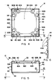
- the upper structure 24 of the top nozzle subassembly 12 consists of a top plate 30 and a sidewall enclosure 32 rigidly connected to and depending from the outer peripheral edge 30A of the top plate 30.
- the top plate 30 has a generally square annular configuration defining a large central opening 34.
- Each of two diagonal corner portions 30B of the top plate 30 has a hole 36 formed therein which permits components of the fuel assembly handling system (not shown) to be inserted therethrough and engaged with the lower surface 30C of the top plate 30 for the purpose of lifting the fuel assembly 10 during installation thereof in or removal thereof from the reactor core.
- Another corner portion 30B of the top plate 30 has a hole 38 providing a reference for properly orientating the fuel assembly 10 in the core, and each corner portion 30B of the top plate 30 has formed therein a pair of holes 40 each of which is countersunk so as to form an annular recess 40A around it in the lower surface 30C of the top plate.
- the sidewall enclosure 32 of the upper structure 24 has a generally square, box-like configuration in that it consists of four generally planar vertical wall portions 42 rigidly interconnected at their opposite vertical edges. At the lower peripheral edge of the sidewall enclosure 32, each wall portion 42 has a narrow inwardly projecting retaining structure 44 composed of a series of tabs or fingers 44A which are spaced apart so as to lend to the retaining structure a generally scalloped or serrated configuration.
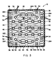
- the lower adapter plate 26 of the top nozzle subassembly 12 is of generally square configuration and flat construction. It is formed of a plurality of cross-laced ligaments or bars 46 defining a plurality of coolant flow openings 48 of oblong shapes.
- the adapter plate 26 has formed therein also circular through-holes 50 which correspond in number and pattern to the guide thimbles 16 and are of a size enabling them to receive upper end portions of the guide thimbles 16 upon installation of the top nozzle subassembly on the guide thimbles.
- the adapter plate 26 is provided at each corner portion 26A thereof with a pair of circular recesses 52 formed in the upper surface 26B of the adapter plate in vertical alignment with the respective pairs of holes 40 and annular recesses 40A of the top plate 24. Coolant flow openings 54 arranged in a generally square pattern extend through the adapter plate 26 from each recess 52.
- the outer peripheral edge of the adapter plate 26 is undercut to define a ledge or seating structure 56 overhanging a continuous peripheral recess or groove 58.
- the resiliently yieldable biasing devices 28 take the form of pairs of coil springs 60 seated at their opposite upper and lower ends 60A, 60B in the recesses 40A, 52 formed in the aligned corner portions 30B, 26A of the top plate 30 and the lower adapter plate 26, respectively, and thus located outside of an outer perimeter of the guide thimbles 16 substantially aligned with the inner peripheral edge 30D of the top plate 30 defining the central opening 34 thereof.
- the top plate 30 has secured thereto stabilizing or guide members 62 in the form of short cylindrical plugs or bars each fitted at its upper end into one of the holes 40 in the top plate 30 and extending therefrom downward axially into the corresponding coil spring 60.
- the stabilizing members 62 serve to stabilize the springs 60 laterally and to direct their expansion and compression along a generally vertical path.
- the stabilizing members 62 have a length such that they extend almost halfway into the springs 60 when the latter are expanded, as seen from Fig. 11, and extend almost down to the adapter plate 26 when the springs 60 are compressed, as shown in Fig. 12.
- the adapter plate 26 When in use, the adapter plate 26, which is attached to the guide thimbles 26 and securely retained thereon in a conventional manner by means of locking tubes 64, will remain in the same position on the guide thimbles in both the expanded condition (Fig. 11) and the compressed condition (Fig. 12) of the top nozzle subassembly 12.
- This adapter plate 26 can be placed substantially, e.g. from about 1 inch (2.54cm) to about 1.5 inches (3.81cm), higher above the upper ends of the fuel rods 18 than can the adapter plate of a conventional top nozzle.
- the adapter plate 26 and the upper structure 24 are not rigidly interconnected but are movable with respect to one another, the adapter plate 26 being axially slidable within the sidewall enclosure 32.
- the retaining structure 44 of the sidewall enclosure 32 and the seating structure 56 of the adapter plate 26 form interengageable means on the lower edge of the enclosure 32 and on a peripheral edge of the adapter plate 26, which means cooperate to prevent separation of the adapter plate 26 and the upper structure 24 from one another.
- the top nozzle subassembly 12 assumes its expanded condition (Fig. 11) when the upper core support plate (not shown) bearing down upon the top plate 30 of the upper structure 24 of the top nozzle subassembly is lifted off and removed, thereby enabling the coil springs 60 to expand and to force the upper structure 24 upward, i.e. away from the adapter plate 26, until the retaining structure 44 on the lower end of the enclosure 32 engages the seating structure 56 on the adapter plate 26 to arrest further movement of the upper structure 24 under the action of the springs 60.
- the adapter plate 26 and top plate 30 are spaced their maximum distance apart and offer ample space enabling components of the fuel assembly handling system to be inserted through the corner holes 36 of the top plate and brought into latching engagement with the latter's underside.
- the top nozzle subassembly 12 assumes its compressed condition (Fig. 12) during installation of the upper core support plate (not shown). As the latter is being lowered upon the top plate 30 of the upper structure 24 of the top nozzle subassembly, it pushes the upper structure 24 downward, causing it to slide down over the adapter plate 26 and causing the holddown springs 60 to be compressed, as illustrated in Fig. 12. It will be appreciated that even though the space between the top plate 30 and the adapter plate 26 might now be less than needed to effectively insert lifting components of the fuel assembly handling system, this is immaterial insofar as there is never any need for the fuel assembly to be handled by the system while it is in the reactor core and the upper core support plate is in place.
- the extra space which exists between the top plate 30 and the adapter plate 26 when the top nozzle subassembly 12 is in its expanded condition shown in Fig. 11, i.e. which exists at a time when handling of the fuel assembly may be necessary, serves in the subassembly's compressed condition (Fig. 12) to accommodate the adapter plate 26 attached to the guide thimbles 16. Consequently, the distance between the adapter plate 26 and the upper ends of the fuel rods 18 can be greater than in fuel assemblies utilizing conventional top nozzle assemblies, thereby allowing for increased fuel-rod growth and for higher fuel-rod burnup in the core.
- the scalloped shape (see Fig. 6) of the retaining structure 44 at the lower end of the enclosure 42 facilitates free movement of the retaining structure past the usual upper closure members, or end plugs, of the fuel rods 18.
- the central opening 34 in the top plate 30 accommodates control rods (not shown) inserted into the guide thimbles 16 in a usual manner.
- the coil springs 60 serve to transmit the necessary hold-down force from the upper core plate (not shown) to the adapter plate 26.
- the number of coil springs 60 employed, and the manner in which they are arranged, offer the advantage of a more even load distribution upon the adapter plate and of thereby helping to prevent fuel assembly bow.
- the sidewall enclosure 32 of the upper structure 24 of the top nozzle subassembly 12, which completely encloses the hold-down springs 60 in both the expanded condition and the compressed condition of the top nozzle subassembly 12, will protect and shield the springs from any lateral forces imposed by coolant flow.
- other forms of hold-down devices different from coil springs such as elongated leaf springs, may be suitable for use with the top nozzle subassembly described above.
Landscapes
- Physics & Mathematics (AREA)
- Engineering & Computer Science (AREA)
- Plasma & Fusion (AREA)
- General Engineering & Computer Science (AREA)
- High Energy & Nuclear Physics (AREA)
- Monitoring And Testing Of Nuclear Reactors (AREA)
- Turbine Rotor Nozzle Sealing (AREA)
Applications Claiming Priority (2)
| Application Number | Priority Date | Filing Date | Title |
|---|---|---|---|
| US353303 | 1989-05-17 | ||
| US07/353,303 US4986959A (en) | 1989-05-17 | 1989-05-17 | Nuclear fuel assembly with expandable top nozzle subassembly |
Publications (3)
| Publication Number | Publication Date |
|---|---|
| EP0398058A2 true EP0398058A2 (de) | 1990-11-22 |
| EP0398058A3 EP0398058A3 (de) | 1993-06-02 |
| EP0398058B1 EP0398058B1 (de) | 1996-06-12 |
Family
ID=23388554
Family Applications (1)
| Application Number | Title | Priority Date | Filing Date |
|---|---|---|---|
| EP90108114A Expired - Lifetime EP0398058B1 (de) | 1989-05-17 | 1990-04-27 | Kopfstück mit ineinanderschiebbarer Baustruktur für Kernbrennelement |
Country Status (6)
| Country | Link |
|---|---|
| US (1) | US4986959A (de) |
| EP (1) | EP0398058B1 (de) |
| JP (1) | JPH036492A (de) |
| KR (1) | KR900019057A (de) |
| DE (1) | DE69027367T2 (de) |
| ES (1) | ES2088919T3 (de) |
Cited By (7)
| Publication number | Priority date | Publication date | Assignee | Title |
|---|---|---|---|---|
| EP0524491A1 (de) * | 1991-07-26 | 1993-01-27 | Westinghouse Electric Corporation | Kernbrennstabbündel mit doppelschaligem Kopfstück |
| WO1993003487A1 (de) * | 1991-08-06 | 1993-02-18 | Siemens Aktiengesellschaft | Kernreaktorbrennelement |
| ES2036955A1 (es) * | 1991-02-11 | 1993-06-01 | Asea Atom Ab | Conjunto de combustible para un reactor nuclear de agua ligera. |
| FR2693825A1 (fr) * | 1992-07-20 | 1994-01-21 | Framatome Sa | Assemblage combustible nucléaire et ensemble grappe-assemblage en comportant application. |
| WO1996007183A1 (en) * | 1994-08-30 | 1996-03-07 | Westinghouse Electric Corporation | Expandable top nozzle and device for securing same to a nuclear fuel assembly |
| EP0704859A1 (de) * | 1994-09-29 | 1996-04-03 | Siemens Power Corporation | Siedewasserreaktorkernbrennstabbündel mit verlängerten Brennstäben |
| EP0935257A3 (de) * | 1998-01-13 | 1999-09-29 | Siemens Aktiengesellschaft | Versandbereites Kernreaktor-Brennelement |
Families Citing this family (12)
| Publication number | Priority date | Publication date | Assignee | Title |
|---|---|---|---|---|
| US5133926A (en) * | 1991-04-18 | 1992-07-28 | Westinghouse Electric Corp. | Extended burnup top nozzle for a nuclear fuel assembly |
| FR2744556B1 (fr) * | 1996-02-02 | 1998-04-24 | Framatome Sa | Assemblage de combustible nucleaire comportant un embout superieur ameliore |
| US6370214B1 (en) * | 1999-07-08 | 2002-04-09 | Framtome Anp Inc. | Radiation induced growth indication apparatus for pressurized water reactor nuclear fuel assemblies |
| US6738447B1 (en) * | 2003-05-22 | 2004-05-18 | Westinghouse Electric Company Llc | High energy absorption top nozzle for a nuclear fuel assembly |
| JP4532127B2 (ja) * | 2004-01-30 | 2010-08-25 | 原子燃料工業株式会社 | 加圧水型原子炉用燃料集合体上部ノズル |
| US20060227923A1 (en) * | 2005-04-08 | 2006-10-12 | Westinghouse Electric Company Llc | Nuclear fuel assembly low pressure drop top nozzle |
| US20060251205A1 (en) * | 2005-05-02 | 2006-11-09 | Westinghouse Electric Co. Llc | In-core fuel restraint assembly |
| JP2007218802A (ja) * | 2006-02-17 | 2007-08-30 | Mitsubishi Heavy Ind Ltd | Pwr原子炉用燃料集合体 |
| CN105006256B (zh) * | 2015-06-18 | 2018-07-20 | 中国核电工程有限公司 | 一种核反应堆上堆芯板 |
| CN110136853B (zh) * | 2019-05-14 | 2022-02-01 | 中国核动力研究设计院 | 一种燃料组件冲击试验支撑装置及其频率调节方法 |
| EP4075447A1 (de) * | 2021-04-16 | 2022-10-19 | Framatome | Obere kernbrennelementdüse mit einer niederhaltevorrichtung |
| CN119541913A (zh) * | 2024-11-25 | 2025-02-28 | 中广核研究院有限公司 | 燃料组件下管座 |
Family Cites Families (18)
| Publication number | Priority date | Publication date | Assignee | Title |
|---|---|---|---|---|
| NL122984C (de) * | 1959-03-25 | |||
| USRE31583E (en) * | 1971-05-20 | 1984-05-08 | Combustion Engineering, Inc. | Fuel assembly hold-down device |
| US4075058A (en) * | 1972-10-11 | 1978-02-21 | Combustion Engineering, Inc. | Articulated fuel assembly |
| US4078967A (en) * | 1976-07-26 | 1978-03-14 | Combustion Engineering, Inc. | Holddown device for nuclear fuel assembly |
| US4072564A (en) * | 1976-09-24 | 1978-02-07 | The Babcock & Wilcox Company | Motion restraining apparatus for a nuclear reactor |
| DE2742946C2 (de) * | 1977-09-23 | 1979-07-26 | Kraftwerk Union Ag, 4330 Muelheim | Federelement für die Niederhaltung von Kernreaktorbrennelementen |
| US4269661A (en) * | 1978-06-15 | 1981-05-26 | Westinghouse Electric Corp. | Top nozzle for a nuclear reactor fuel assembly |
| FR2520147B1 (fr) * | 1982-01-18 | 1985-10-25 | Commissariat Energie Atomique | Piece d'extremite d'assemblage combustible de reacteurs nucleaires dans laquelle les parois laterales sont elastiques |
| US4534933A (en) * | 1983-10-17 | 1985-08-13 | Westinghouse Electric Corp. | Nuclear reactor fuel assembly with improved top nozzle and hold-down means |
| US4603027A (en) * | 1983-12-21 | 1986-07-29 | Westinghouse Electric Corp. | Removable top nozzle and tool for a nuclear reactor fuel assembly |
| US4572816A (en) * | 1983-12-21 | 1986-02-25 | Westinghouse Electric Corp. | Reconstituting a nuclear reactor fuel assembly |
| GB2163888B (en) * | 1984-08-30 | 1988-06-22 | Atomic Energy Authority Uk | Fission gas plenum chamber for nuclear fuel element sub-assembly |
| US4628581A (en) * | 1985-01-25 | 1986-12-16 | Westinghouse Electric Corp. | Apparatus and method for preassembling a top nozzle subassembly for a nuclear reactor fuel assembly |
| US4670213A (en) * | 1985-02-12 | 1987-06-02 | Westinghouse Electric Corp. | Removable top nozzle subassembly for a reconstitutable nuclear fuel assembly |
| US4762676A (en) * | 1985-07-05 | 1988-08-09 | Westinghouse Electric Corp. | Top nozzle adapter plate with fuel rod capture grid having pressure drop adjusting means |
| US4707326A (en) * | 1985-07-26 | 1987-11-17 | Westinghouse Electric Corp. | Arrangement and method for attaching and reattaching a top nozzle in a reconstitutable nuclear fuel assembly |
| FR2589614B1 (fr) * | 1985-08-09 | 1988-01-08 | Fragema Framatome & Cogema | Assemblage combustible nucleaire a structure de maintien et dispositif anti-envol |
| US4692304A (en) * | 1985-12-23 | 1987-09-08 | Westinghouse Electric Corp. | Removable and reusable locking pin for top nozzle assembly and disassembly |
-
1989
- 1989-05-17 US US07/353,303 patent/US4986959A/en not_active Expired - Lifetime
-
1990
- 1990-04-27 EP EP90108114A patent/EP0398058B1/de not_active Expired - Lifetime
- 1990-04-27 ES ES90108114T patent/ES2088919T3/es not_active Expired - Lifetime
- 1990-04-27 DE DE69027367T patent/DE69027367T2/de not_active Expired - Fee Related
- 1990-05-17 JP JP2125633A patent/JPH036492A/ja active Pending
- 1990-05-17 KR KR1019900007081A patent/KR900019057A/ko not_active Ceased
Cited By (7)
| Publication number | Priority date | Publication date | Assignee | Title |
|---|---|---|---|---|
| ES2036955A1 (es) * | 1991-02-11 | 1993-06-01 | Asea Atom Ab | Conjunto de combustible para un reactor nuclear de agua ligera. |
| EP0524491A1 (de) * | 1991-07-26 | 1993-01-27 | Westinghouse Electric Corporation | Kernbrennstabbündel mit doppelschaligem Kopfstück |
| WO1993003487A1 (de) * | 1991-08-06 | 1993-02-18 | Siemens Aktiengesellschaft | Kernreaktorbrennelement |
| FR2693825A1 (fr) * | 1992-07-20 | 1994-01-21 | Framatome Sa | Assemblage combustible nucléaire et ensemble grappe-assemblage en comportant application. |
| WO1996007183A1 (en) * | 1994-08-30 | 1996-03-07 | Westinghouse Electric Corporation | Expandable top nozzle and device for securing same to a nuclear fuel assembly |
| EP0704859A1 (de) * | 1994-09-29 | 1996-04-03 | Siemens Power Corporation | Siedewasserreaktorkernbrennstabbündel mit verlängerten Brennstäben |
| EP0935257A3 (de) * | 1998-01-13 | 1999-09-29 | Siemens Aktiengesellschaft | Versandbereites Kernreaktor-Brennelement |
Also Published As
| Publication number | Publication date |
|---|---|
| EP0398058A3 (de) | 1993-06-02 |
| JPH036492A (ja) | 1991-01-11 |
| DE69027367D1 (de) | 1996-07-18 |
| EP0398058B1 (de) | 1996-06-12 |
| ES2088919T3 (es) | 1996-10-01 |
| US4986959A (en) | 1991-01-22 |
| KR900019057A (ko) | 1990-12-22 |
| DE69027367T2 (de) | 1996-10-10 |
Similar Documents
| Publication | Publication Date | Title |
|---|---|---|
| EP0398058B1 (de) | Kopfstück mit ineinanderschiebbarer Baustruktur für Kernbrennelement | |
| EP0138606B1 (de) | Kernreaktorbrennelement mit Kopfteil und Retentionssystem | |
| EP0372214B1 (de) | Trümmerfängerabstandshalter mit Haltefedern | |
| EP0422950B1 (de) | Kernbrennstabbündel mit Trümmerfänger | |
| US5748694A (en) | Fuel bundle filter for a nuclear reactor fuel bundle assembly | |
| US4585616A (en) | Nuclear fuel spacer grid with improved outer straps | |
| EP0146896B1 (de) | Partielles Abstandsgitter für ein Kernreaktorbrennstoffbündel | |
| EP0704858B1 (de) | Kernbrennstabbündel mit vergrösserter aktiver Höhe für einen Druckwasserreaktor | |
| US4357298A (en) | Nuclear fuel assembly space arrangement | |
| JPH0545196B2 (de) | ||
| US4420458A (en) | Nuclear fuel assembly with coolant conducting tube | |
| US4585615A (en) | Nuclear fuel spacer grid with improved grid straps | |
| US4828792A (en) | Nuclear fuel assembly with holding structure and hold down device | |
| US4389369A (en) | Bi-metallic grid for a nuclear reactor fuel assembly | |
| EP0410171A1 (de) | Schutzvorrichtung für das untere Endteil einer Kernbrennstabhülle | |
| EP0290865A2 (de) | Kernreaktorkern mit Brennelementen in Kernumfassungsnahen Positionen | |
| US5053191A (en) | Fuel assembly holddown spring | |
| EP0386501B1 (de) | Klemmen für Niederhaltefedern auf dem Kopfstück eines Brennelementes | |
| US4304635A (en) | Fuel assembly for nuclear boiling-water reactors | |
| US4670213A (en) | Removable top nozzle subassembly for a reconstitutable nuclear fuel assembly | |
| US5274685A (en) | Non-levitating PWR fuel assembly | |
| US5200142A (en) | Nuclear fuel assembly top nozzle with improved peripheral hold-down assembly | |
| US4692304A (en) | Removable and reusable locking pin for top nozzle assembly and disassembly | |
| EP0545587B1 (de) | Brennstabbündel und Abstandshalter zum Einsatz von verjüngten Brennstäben | |
| US5084237A (en) | Side insertable spacer |
Legal Events
| Date | Code | Title | Description |
|---|---|---|---|
| PUAI | Public reference made under article 153(3) epc to a published international application that has entered the european phase |
Free format text: ORIGINAL CODE: 0009012 |
|
| AK | Designated contracting states |
Kind code of ref document: A2 Designated state(s): BE DE ES FR GB IT SE |
|
| RTI1 | Title (correction) | ||
| PUAL | Search report despatched |
Free format text: ORIGINAL CODE: 0009013 |
|
| AK | Designated contracting states |
Kind code of ref document: A3 Designated state(s): BE DE ES FR GB IT SE |
|
| 17P | Request for examination filed |
Effective date: 19930621 |
|
| 17Q | First examination report despatched |
Effective date: 19950111 |
|
| GRAH | Despatch of communication of intention to grant a patent |
Free format text: ORIGINAL CODE: EPIDOS IGRA |
|
| GRAA | (expected) grant |
Free format text: ORIGINAL CODE: 0009210 |
|
| AK | Designated contracting states |
Kind code of ref document: B1 Designated state(s): BE DE ES FR GB IT SE |
|
| ET | Fr: translation filed | ||
| REF | Corresponds to: |
Ref document number: 69027367 Country of ref document: DE Date of ref document: 19960718 |
|
| ITF | It: translation for a ep patent filed | ||
| REG | Reference to a national code |
Ref country code: ES Ref legal event code: FG2A Ref document number: 2088919 Country of ref document: ES Kind code of ref document: T3 |
|
| REG | Reference to a national code |
Ref country code: ES Ref legal event code: FG2A Ref document number: 2088919 Country of ref document: ES Kind code of ref document: T3 |
|
| PLBE | No opposition filed within time limit |
Free format text: ORIGINAL CODE: 0009261 |
|
| STAA | Information on the status of an ep patent application or granted ep patent |
Free format text: STATUS: NO OPPOSITION FILED WITHIN TIME LIMIT |
|
| 26N | No opposition filed | ||
| REG | Reference to a national code |
Ref country code: GB Ref legal event code: IF02 |
|
| PGFP | Annual fee paid to national office [announced via postgrant information from national office to epo] |
Ref country code: SE Payment date: 20020405 Year of fee payment: 13 |
|
| PGFP | Annual fee paid to national office [announced via postgrant information from national office to epo] |
Ref country code: ES Payment date: 20020411 Year of fee payment: 13 |
|
| PG25 | Lapsed in a contracting state [announced via postgrant information from national office to epo] |
Ref country code: SE Free format text: LAPSE BECAUSE OF NON-PAYMENT OF DUE FEES Effective date: 20030428 Ref country code: ES Free format text: LAPSE BECAUSE OF NON-PAYMENT OF DUE FEES Effective date: 20030428 |
|
| PGFP | Annual fee paid to national office [announced via postgrant information from national office to epo] |
Ref country code: DE Payment date: 20030430 Year of fee payment: 14 |
|
| EUG | Se: european patent has lapsed | ||
| PGFP | Annual fee paid to national office [announced via postgrant information from national office to epo] |
Ref country code: FR Payment date: 20040402 Year of fee payment: 15 |
|
| PGFP | Annual fee paid to national office [announced via postgrant information from national office to epo] |
Ref country code: GB Payment date: 20040416 Year of fee payment: 15 |
|
| PGFP | Annual fee paid to national office [announced via postgrant information from national office to epo] |
Ref country code: BE Payment date: 20040507 Year of fee payment: 15 |
|
| REG | Reference to a national code |
Ref country code: ES Ref legal event code: FD2A Effective date: 20030428 |
|
| PG25 | Lapsed in a contracting state [announced via postgrant information from national office to epo] |
Ref country code: DE Free format text: LAPSE BECAUSE OF NON-PAYMENT OF DUE FEES Effective date: 20041103 |
|
| PG25 | Lapsed in a contracting state [announced via postgrant information from national office to epo] |
Ref country code: IT Free format text: LAPSE BECAUSE OF NON-PAYMENT OF DUE FEES Effective date: 20050427 Ref country code: GB Free format text: LAPSE BECAUSE OF NON-PAYMENT OF DUE FEES Effective date: 20050427 |
|
| PG25 | Lapsed in a contracting state [announced via postgrant information from national office to epo] |
Ref country code: BE Free format text: LAPSE BECAUSE OF NON-PAYMENT OF DUE FEES Effective date: 20050430 |
|
| BERE | Be: lapsed |
Owner name: *WESTINHOUSE ELECTRIC CY LLC Effective date: 20050430 |
|
| GBPC | Gb: european patent ceased through non-payment of renewal fee |
Effective date: 20050427 |
|
| PG25 | Lapsed in a contracting state [announced via postgrant information from national office to epo] |
Ref country code: FR Free format text: LAPSE BECAUSE OF NON-PAYMENT OF DUE FEES Effective date: 20051230 |
|
| REG | Reference to a national code |
Ref country code: FR Ref legal event code: ST Effective date: 20051230 |
|
| BERE | Be: lapsed |
Owner name: *WESTINHOUSE ELECTRIC CY LLC Effective date: 20050430 |