EP0704859A1 - Siedewasserreaktorkernbrennstabbündel mit verlängerten Brennstäben - Google Patents
Siedewasserreaktorkernbrennstabbündel mit verlängerten Brennstäben Download PDFInfo
- Publication number
- EP0704859A1 EP0704859A1 EP95112556A EP95112556A EP0704859A1 EP 0704859 A1 EP0704859 A1 EP 0704859A1 EP 95112556 A EP95112556 A EP 95112556A EP 95112556 A EP95112556 A EP 95112556A EP 0704859 A1 EP0704859 A1 EP 0704859A1
- Authority
- EP
- European Patent Office
- Prior art keywords
- fuel
- fuel rod
- support plate
- rod support
- assembly
- Prior art date
- Legal status (The legal status is an assumption and is not a legal conclusion. Google has not performed a legal analysis and makes no representation as to the accuracy of the status listed.)
- Granted
Links
Images


Classifications
-
- G—PHYSICS
- G21—NUCLEAR PHYSICS; NUCLEAR ENGINEERING
- G21C—NUCLEAR REACTORS
- G21C3/00—Reactor fuel elements and their assemblies; Selection of substances for use as reactor fuel elements
- G21C3/30—Assemblies of a number of fuel elements in the form of a rigid unit
- G21C3/32—Bundles of parallel pin-, rod-, or tube-shaped fuel elements
- G21C3/33—Supporting or hanging of elements in the bundle; Means forming part of the bundle for inserting it into, or removing it from, the core; Means for coupling adjacent bundles
- G21C3/3305—Lower nozzle
-
- G—PHYSICS
- G21—NUCLEAR PHYSICS; NUCLEAR ENGINEERING
- G21C—NUCLEAR REACTORS
- G21C3/00—Reactor fuel elements and their assemblies; Selection of substances for use as reactor fuel elements
- G21C3/30—Assemblies of a number of fuel elements in the form of a rigid unit
- G21C3/32—Bundles of parallel pin-, rod-, or tube-shaped fuel elements
- G21C3/33—Supporting or hanging of elements in the bundle; Means forming part of the bundle for inserting it into, or removing it from, the core; Means for coupling adjacent bundles
- G21C3/331—Comprising hold-down means, e.g. springs
-
- Y—GENERAL TAGGING OF NEW TECHNOLOGICAL DEVELOPMENTS; GENERAL TAGGING OF CROSS-SECTIONAL TECHNOLOGIES SPANNING OVER SEVERAL SECTIONS OF THE IPC; TECHNICAL SUBJECTS COVERED BY FORMER USPC CROSS-REFERENCE ART COLLECTIONS [XRACs] AND DIGESTS
- Y02—TECHNOLOGIES OR APPLICATIONS FOR MITIGATION OR ADAPTATION AGAINST CLIMATE CHANGE
- Y02E—REDUCTION OF GREENHOUSE GAS [GHG] EMISSIONS, RELATED TO ENERGY GENERATION, TRANSMISSION OR DISTRIBUTION
- Y02E30/00—Energy generation of nuclear origin
- Y02E30/30—Nuclear fission reactors
Definitions
- the present invention relates generally to nuclear fuel assemblies for nuclear reactors, and more particularly to increasing the amount of power generated by the fuel assembly and limiting flow induced vibrations of the fuel rods in the fuel assembly.
- BWR boiling water reactor
- water as the coolant moderator typically enters the fuel assembly from a bottom portion, flows through the fuel assembly, and exits to an uppermost portion.
- elongated nuclear fuel rods having end caps at opposite ends are supported at their lower and upper ends between lower and upper tie plates, respectively.
- the tie plates provide the basic upper and lower structural elements for the fuel assembly in a configuration for interfacing with the reactor core support and for fuel handling.
- the tie plates also serve to maintain the fuel rod spacing at the ends of the fuel rods.
- Spacer grids are positioned between the upper and lower tie plates for retaining the fuel rods parallel to one another and with fixed spacing in a fixed geometry.
- the restraining holes in the lower tie plate which receive the fuel rod end caps are sized so the fuel rod end caps when positioned in their corresponding restraining holes are free to move.
- a gap of about 2 to 6 mils exists between the outer wall of the end cap and the wall of the restraining hole.
- a boiling water reactor nuclear fuel assembly having a predetermined overall length for placement in a nuclear reactor core having an upper tie plate, a lower tie plate comprising a fuel rod support plate adapted to have an aperture for receiving a fuel rod end cap of a nuclear fuel rod and an inlet nozzle into which coolant/moderator enters the fuel assembly, the fuel rod support plate and the inlet nozzle defining a transition zone from the inlet nozzle to the fuel rod support plate for distributing the coolant moderator which enters the inlet nozzle before passing through the fuel rod support plate, said transition zone having a predetermined height.
- the fuel assembly further having a plurality of spaced apart nuclear fuel rods having an active portion containing fissionable material, at least one of the plurality of nuclear fuel rods having an end cap disposed at a lower end and extending axially outward therefrom for being positioned within the aperture in the fuel rod support plate, wherein the position of the fuel rod support plate is lowered into the transition zone thereby decreasing the height of the transition zone, and the length of at least one of the plurality of nuclear fuel rods is increased by extending the length of the active portion of at least one of the plurality of nuclear fuel rods into the transition zone that had been occupied by the fuel rod support plate.
- a boiling water reactor fuel assembly design typically used in reactors in the U.S. is generally shown at 10 having elongated nuclear fuel rods 12 which are supported between a lower tie plate 14 and upper tie plate 16.
- Each fuel rod generally includes a zirconium alloy tube within which is nuclear fuel pellets.
- Lower tie plate 14 and upper tie plate 16 are connected structurally by tie rods 20 positioned within the array of fuel rods.
- a plurality of spacer grids 18 provide intermediate support of the fuel rods 12 over the length of the fuel assembly and maintain them in spaced relationship while restraining them from lateral vibration. Only five of the spacer grids 18 are shown in Figure 1 for clarity of illustration.
- Outer channel 22 completely surrounds the fuel assembly on all four sides and extends from the lower tie plate to the upper tie plate.
- a boiling water reactor fuel assembly of a design used in reactors outside the U.S. and typically in Europe is generally shown at 30 in Figure 2 and similarly has fuel rods 32 supported between a lower tie plate 34 and upper tie plate 36, tie rods 40, spacer grids 38, and outer channel 42.
- lower tie plate 14 is shown with tie rods removed. Fuel rod end caps 13 are positioned in respective holes 14e of fuel rod support plate 14c.
- Lower tie plate 14 serves as the interfacing component of the fuel assembly with the lower core support structure (not shown) of the reactor. Lower tie plate 14 is configured to provide a transition zone 14f from the circular coolant inlet 14a in inlet nozzle 14b (which circular inlet matches the discharge of the lower core support) to the square shaped fuel rod support plate 14c.
- the distance between the bottom of the fuel rods and the bottom of coolant inlet nozzle 14b, i.e. the transition zone 14f, is approximately 5 inches.
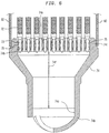
- Lower tie plate 34 serves as the interfacing component of the fuel assembly with the lower core support of the reactor and includes a generally square fuel rod support plate 34c. Fuel rod end caps 33 are positioned in respective holes 34e of fuel rod support plate 34c. Lower tie plate 34 is configured to provide a transition zone 34f from the circular coolant inlet 34a in inlet nozzle 34b to the square shaped fuel rod support plate 34c. The distance between the bottom of the fuel rods and the bottom of inlet nozzle 34b, i.e. the transition zone 34f, is approximately 8 inches.
- the internal space or transition zone from the inlet nozzle to the fuel rod support plate in which the lower ends of the fuel rods are positioned is open space into which coolant moderator first enters the fuel assembly and then distributes before passing through the fuel rod support plate.
- the potential for increased lateral vibration resulting from increased cross flows created by the redistribution of coolant flow from lowering the height of the fuel rod support plate of the lower tie plate to increase the length of the fuel rods is eliminated by the use of a spring element in the fuel rod support plate of the lower tie plate.
- the spring element exerts lateral forces on the fuel rod end cap to overcome the vibratory forces induced by the coolant moderator flow thereby preventing lateral motion and possible fuel rod fretting.
- flow induced vibration load can be controlled to prevent vibration induced fuel rod wear by the use of a spring which preloads the fuel rod against hardstops in a diametrically open radial spacer grid arrangement
- lateral loads induced from differential thermal expansion and irradiation growth could significantly overpower spring loads used to prevent fuel rod vibration induced wear.
- reactor fuel rod bow and distortion can occur during fuel assembly irradiation.
- the upper and lower tie plates are required to maintain axial and radial alignment with the fuel rods and the support structure. Since fuel rod distortion must be controlled, devices which are incapable of providing rigid radial restraint of the fuel rods within the lower tie plate are unsuitable.
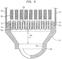
- lower tie plate 54 has a shortened transition zone 54f above which is positioned fuel rod support plate 54c. Fuel rod end caps 53 of lengthened fuel rods 52 are positioned within holes 54e.
- each hole 54e is a bore 54h which accommodates spring 55 which exerts lateral forces against the fuel rod end cap 53 to restrain the fuel rod and overcome the vibratory forces induced by the coolant moderator flow thereby preventing lateral motion and possible fuel rod fretting.
- FIG. 9A a portion of fuel rod support plate 54c is shown broken away with a spring element 55 positioned in bore 54h within hole 54e of shank housing 54d.
- a perspective view of spring element 55 is shown in Figure 9B.
- Spring 55 exerts a lateral force on the outer wall of the fuel rod end cap 53.
- all of the other fuel rods of the fuel assembly can similarly be laterally restrained by springs within bores in the support plate.
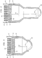
- FIG. 6 The lower portion of the fuel assembly in accordance with the present invention for use in other BWR designs is shown in Figure 6 in which the fuel rod support plate has similarly been lowered into the transition zone of the prior art fuel assembly shown in Figures 2 and 4.
- the fuel rods have been extended down to the lowered fuel rod support plate and are restrained laterally by springs.
- Lower tie plate 74 has a shortened transition zone 74f.
- Fuel rod support plate 74c has a bore 74h within each hole 74e to accommodate springs 75 each of which exerts a lateral force against a fuel rod end cap 73 of a lengthened fuel rod 72.
- Figure 7 which shows the comparison of the relative height of the transition zone of the prior art fuel assembly (Fig. 3) to the transition zone of the fuel assembly shown in Figure 5 in accordance with the present invention
- the distance X that the fuel rod support plate is lowered into the transition zone is equal to the increased length X' of the fuel rods.
- Figure 8 shows that the distance Y that the fuel rod support plate is lowered into the transition zone of another BWR design (Fig. 4) is equal to the increased length Y' of the fuel rods of the fuel assembly shown in Figure 6.
- Spring element 55 shown positioned within the modified fuel rod support plate 54c in Figure 9A is representative of several different variations of springs which can be used to exert a lateral force against the fuel rod end cap to restrain the fuel rod against flow induced vibrations.
- a semi-fixed simply supported C-ring Figure 12A
- a cantilever C-ring Figure 12B
- a tubular C-ring Figure 12C
- Other forms of spring elements such as coil springs or simply supported springs can also be used. Any one of these or equivalent spring elements can be substituted for the one shown in Figure 9 to provide the lateral force against the fuel rod end cap 53 to support the fuel rod against flow induced vibrations.
- Each of the spring elements do not increase the pressure drop from the inlet nozzle across the lower tie plate.
- the upper surface of fuel rod support plate 14c is provided with a fuel rod support plate surface adapter 64 which has the same profile as and aligns with fuel rod support plate (See Figures 10 and 11.)
- Surface adapter 64 has fuel rod guides 64a each of which is apertured at its center to allow the fuel rod end cap of the lengthened fuel rod to pass through it and into hole 14e in the fuel rod support plate 14c.
- Fuel rod guides 64a of surface adapter 64 align with holes 14e in the fuel rod support plate 14c to receive end cap 53 of the extended fuel rod 52.
- Cantilever springs 64b extend from fuel rod guides 64a and are angled and thereby biased so as to exert a lateral force against end cap 53 of each extended fuel rod to restrain the fuel rods against flow induced vibration and thereby eliminate fretting wear.
- Each fuel rod guide 64a is at an angle to the surface adapter to form a chamfer for guiding each fuel rod end cap 53 into its respective hole 14e in the fuel rod support plate 14c.
- Lowering the height of the fuel rod support plate provides approximately 1 to 4 inches of additional length for the fuel rods. This increase in fuel rod length can be used to increase the power of the fuel assembly, improve reactor, fuel rod and fuel assembly operating margins, or extend fuel rod operating life. These benefits amount to performance improvements of approximately $20 per kilogram of UO2 for an operating nuclear reactor.
- an obstacle to increasing power by increasing reactor coolant flow beyond 100% nominal operation is prohibited due to the increased fuel rod vibration and possible fretting due to the increased reactor coolant flow.
- the restriction on exceeding the maximum reactor coolant flow rate can be eliminated and a higher reactor coolant flow rate and power can thereby be attained.
- This increase in power is in addition to the increased power that is obtained by increasing the length of the active portion of the fuel rod.
Landscapes
- Physics & Mathematics (AREA)
- Engineering & Computer Science (AREA)
- Plasma & Fusion (AREA)
- General Engineering & Computer Science (AREA)
- High Energy & Nuclear Physics (AREA)
- Heat-Exchange Devices With Radiators And Conduit Assemblies (AREA)
- Monitoring And Testing Of Nuclear Reactors (AREA)
- Structure Of Emergency Protection For Nuclear Reactors (AREA)
Applications Claiming Priority (2)
| Application Number | Priority Date | Filing Date | Title |
|---|---|---|---|
| US08/315,035 US5490191A (en) | 1994-09-29 | 1994-09-29 | BWR nuclear fuel assembly |
| US315035 | 1994-09-29 |
Publications (2)
| Publication Number | Publication Date |
|---|---|
| EP0704859A1 true EP0704859A1 (de) | 1996-04-03 |
| EP0704859B1 EP0704859B1 (de) | 1999-03-10 |
Family
ID=23222584
Family Applications (1)
| Application Number | Title | Priority Date | Filing Date |
|---|---|---|---|
| EP95112556A Expired - Lifetime EP0704859B1 (de) | 1994-09-29 | 1995-08-09 | Siedewasserreaktorkernbrennstabbündel mit verlängerten Brennstäben |
Country Status (6)
| Country | Link |
|---|---|
| US (1) | US5490191A (de) |
| EP (1) | EP0704859B1 (de) |
| JP (1) | JPH08114691A (de) |
| DE (1) | DE69508174T2 (de) |
| ES (1) | ES2133628T3 (de) |
| TW (1) | TW316982B (de) |
Cited By (1)
| Publication number | Priority date | Publication date | Assignee | Title |
|---|---|---|---|---|
| DE19906356C1 (de) * | 1999-02-16 | 2000-06-29 | Siemens Ag | Brennelement für einen wassergekühlten Kernreaktor |
Families Citing this family (7)
| Publication number | Priority date | Publication date | Assignee | Title |
|---|---|---|---|---|
| FR2864323B1 (fr) * | 2003-12-22 | 2008-07-18 | Framatome Anp | Embout d'extremite d'assemblage de combustible a moyens de maintien des extremites des crayons et assemblage correspondant |
| DE102004059195B3 (de) * | 2004-12-09 | 2006-02-23 | Framatome Anp Gmbh | Brennelement für einen Siedewasserreaktor |
| EP2405443A1 (de) * | 2010-07-06 | 2012-01-11 | Areva NP | SWR-Brennelementeinheit mit einrastender Hülsenfeder |
| US20140241486A1 (en) * | 2013-02-26 | 2014-08-28 | Babcock & Wilcox Mpower, Inc. | Fuel assembly |
| JP6560861B2 (ja) * | 2014-12-15 | 2019-08-14 | 株式会社日立製作所 | 燃料集合体 |
| RU2589446C1 (ru) * | 2015-09-24 | 2016-07-10 | Общество с ограниченной ответственностью "Научно-технический центр инноваций" | Медицинский источник нейтронов, ядерный реактор для медицинского источника нейтронов, способ применения медицинского источника нейтронов |
| US11437155B2 (en) * | 2017-02-28 | 2022-09-06 | Westinghouse Electric Company Llc | Three dimensional printed precision magnets for fuel assembly |
Citations (4)
| Publication number | Priority date | Publication date | Assignee | Title |
|---|---|---|---|---|
| US4671924A (en) * | 1985-05-02 | 1987-06-09 | Westinghouse Electric Corp. | Hold-down device of fuel assembly top nozzle employing leaf springs |
| JPH01232290A (ja) * | 1988-03-11 | 1989-09-18 | Nippon Nuclear Fuel Dev Co Ltd | 核燃料集合体の上部タイプレート |
| EP0398058A2 (de) * | 1989-05-17 | 1990-11-22 | Westinghouse Electric Corporation | Kopfstück mit ineinanderschiebbarer Baustruktur für Kernbrennelement |
| US5133926A (en) * | 1991-04-18 | 1992-07-28 | Westinghouse Electric Corp. | Extended burnup top nozzle for a nuclear fuel assembly |
Family Cites Families (19)
| Publication number | Priority date | Publication date | Assignee | Title |
|---|---|---|---|---|
| US3015616A (en) * | 1956-11-02 | 1962-01-02 | Westinghouse Electric Corp | Rod type fuel assembly |
| US3137638A (en) * | 1959-05-23 | 1964-06-16 | Siemens Ag | Neutronic reactor fuel elements |
| US3619367A (en) * | 1967-06-06 | 1971-11-09 | Commissariat Energie Atomique | Fuel assembly with solid end-fitting |
| US3607642A (en) * | 1968-11-26 | 1971-09-21 | Gen Electric | Nuclear reactor fuel assembly |
| US3660231A (en) * | 1968-11-26 | 1972-05-02 | Gen Electric | Steam cooled nuclear reactor |
| BE789401A (fr) * | 1971-09-30 | 1973-01-15 | Gen Electric | Assemblage de barres de combustible pour reacteurs nucleaires |
| US4038137A (en) * | 1973-09-26 | 1977-07-26 | Exxon Nuclear Company, Inc. | Locking means for fuel bundles |
| US4152206A (en) * | 1977-06-06 | 1979-05-01 | The Babcock & Wilcox Company | Nuclear fuel element end fitting |
| SE414091B (sv) * | 1978-10-13 | 1980-07-07 | Asea Atom Ab | Brenslepatron |
| US4344915A (en) * | 1980-09-17 | 1982-08-17 | The United States Of America As Represented By The United States Department Of Energy | Nuclear reactor fuel rod attachment system |
| US4357298A (en) * | 1980-10-10 | 1982-11-02 | General Electric Company | Nuclear fuel assembly space arrangement |
| US4452755A (en) * | 1982-01-29 | 1984-06-05 | The United States Of America As Represented By The United States Department Of Energy | Fuel rod retention device for a nuclear reactor |
| FR2522866B1 (fr) * | 1982-03-04 | 1987-12-31 | Commissariat Energie Atomique | Assemblage combustible de reacteur nucleaire |
| US4664879A (en) * | 1984-07-26 | 1987-05-12 | Westinghouse Electric Corp. | Guide tube flow restrictor |
| US4684501A (en) * | 1985-11-27 | 1987-08-04 | Westinghouse Electric Corp. | Compliant inserts mounted in upper tie plate of BWR fuel assembly |
| US4980121A (en) * | 1989-07-28 | 1990-12-25 | Westinghouse Electric Corp. | Protective device for lower end portion of a nuclear fuel rod cladding |
| US5085827A (en) * | 1989-12-27 | 1992-02-04 | General Electric Company | Nuclear fuel assembly spacer and loop spring with enhanced flexibility |
| EP0517728B1 (de) * | 1990-02-28 | 1995-07-12 | Siemens Aktiengesellschaft | Kernreaktorbrennelement mit einem tragenden kühlmittelrohr |
| US5069865A (en) * | 1990-12-14 | 1991-12-03 | Westinghouse Electric Corp. | Method of forming a gripper cavity in a fuel rod end plug |
-
1994
- 1994-09-29 US US08/315,035 patent/US5490191A/en not_active Expired - Lifetime
-
1995
- 1995-08-09 ES ES95112556T patent/ES2133628T3/es not_active Expired - Lifetime
- 1995-08-09 EP EP95112556A patent/EP0704859B1/de not_active Expired - Lifetime
- 1995-08-09 DE DE69508174T patent/DE69508174T2/de not_active Expired - Fee Related
- 1995-09-27 JP JP7272117A patent/JPH08114691A/ja active Pending
- 1995-10-21 TW TW084111159A patent/TW316982B/zh active
Patent Citations (4)
| Publication number | Priority date | Publication date | Assignee | Title |
|---|---|---|---|---|
| US4671924A (en) * | 1985-05-02 | 1987-06-09 | Westinghouse Electric Corp. | Hold-down device of fuel assembly top nozzle employing leaf springs |
| JPH01232290A (ja) * | 1988-03-11 | 1989-09-18 | Nippon Nuclear Fuel Dev Co Ltd | 核燃料集合体の上部タイプレート |
| EP0398058A2 (de) * | 1989-05-17 | 1990-11-22 | Westinghouse Electric Corporation | Kopfstück mit ineinanderschiebbarer Baustruktur für Kernbrennelement |
| US5133926A (en) * | 1991-04-18 | 1992-07-28 | Westinghouse Electric Corp. | Extended burnup top nozzle for a nuclear fuel assembly |
Non-Patent Citations (1)
| Title |
|---|
| PATENT ABSTRACTS OF JAPAN vol. 13, no. 554 (P - 973)<3902> 11 December 1989 (1989-12-11) * |
Cited By (1)
| Publication number | Priority date | Publication date | Assignee | Title |
|---|---|---|---|---|
| DE19906356C1 (de) * | 1999-02-16 | 2000-06-29 | Siemens Ag | Brennelement für einen wassergekühlten Kernreaktor |
Also Published As
| Publication number | Publication date |
|---|---|
| DE69508174T2 (de) | 1999-12-23 |
| DE69508174D1 (de) | 1999-04-15 |
| JPH08114691A (ja) | 1996-05-07 |
| TW316982B (de) | 1997-10-01 |
| US5490191A (en) | 1996-02-06 |
| EP0704859B1 (de) | 1999-03-10 |
| ES2133628T3 (es) | 1999-09-16 |
Similar Documents
| Publication | Publication Date | Title |
|---|---|---|
| US4675154A (en) | Nuclear fuel assembly with large coolant conducting tube | |
| US4508679A (en) | Nuclear fuel assembly spacer | |
| EP0704858B1 (de) | Kernbrennstabbündel mit vergrösserter aktiver Höhe für einen Druckwasserreaktor | |
| EP1012852B1 (de) | Kerbrennstoffeinheit | |
| US4420458A (en) | Nuclear fuel assembly with coolant conducting tube | |
| EP0146896B1 (de) | Partielles Abstandsgitter für ein Kernreaktorbrennstoffbündel | |
| US5666389A (en) | Fuel assembly and spacer for a nuclear reactor | |
| JPH0222353B2 (de) | ||
| JPH0545196B2 (de) | ||
| JPS61191990A (ja) | 原子炉用の燃料集合体 | |
| US4671924A (en) | Hold-down device of fuel assembly top nozzle employing leaf springs | |
| EP0175455B1 (de) | Kernreaktorregelstab mit verminderter Wirksamkeit an seiner Spitze | |
| US5490191A (en) | BWR nuclear fuel assembly | |
| EP0555081A1 (de) | Abstandhalter mit Dampfabscheider | |
| US6347130B1 (en) | Fuel assembly with short fuel units | |
| US4587704A (en) | Method of mounting a continuous loop spring on a nuclear fuel spacer | |
| US5949839A (en) | Fuel assembly for a boiling water reactor | |
| EP0871960B1 (de) | Brennstabbündel für siedewasserreaktor | |
| JPS60244892A (ja) | 核燃料集合体 | |
| US6298108B1 (en) | Nuclear fuel rod with upward-shifted pellet stack and a device to realize same | |
| US6813327B1 (en) | Core support for an F-lattice core of a boiling water nuclear reactor | |
| EP0526777A1 (de) | Siedewasserbrennstobbündel mit Wasserrohren | |
| JPH09166676A (ja) | 荷重支持にチャネルを用いる燃料集合体構造および方法 | |
| JPH07128474A (ja) | 原子炉炉心 | |
| EP2661751B1 (de) | Luftfederanordnung für kernbrennstäbe |
Legal Events
| Date | Code | Title | Description |
|---|---|---|---|
| PUAI | Public reference made under article 153(3) epc to a published international application that has entered the european phase |
Free format text: ORIGINAL CODE: 0009012 |
|
| AK | Designated contracting states |
Kind code of ref document: A1 Designated state(s): DE ES SE |
|
| K1C1 | Correction of patent application (title page) published |
Effective date: 19960403 |
|
| 17P | Request for examination filed |
Effective date: 19960927 |
|
| 17Q | First examination report despatched |
Effective date: 19970915 |
|
| GRAG | Despatch of communication of intention to grant |
Free format text: ORIGINAL CODE: EPIDOS AGRA |
|
| GRAG | Despatch of communication of intention to grant |
Free format text: ORIGINAL CODE: EPIDOS AGRA |
|
| GRAH | Despatch of communication of intention to grant a patent |
Free format text: ORIGINAL CODE: EPIDOS IGRA |
|
| GRAH | Despatch of communication of intention to grant a patent |
Free format text: ORIGINAL CODE: EPIDOS IGRA |
|
| GRAA | (expected) grant |
Free format text: ORIGINAL CODE: 0009210 |
|
| AK | Designated contracting states |
Kind code of ref document: B1 Designated state(s): DE ES SE |
|
| REF | Corresponds to: |
Ref document number: 69508174 Country of ref document: DE Date of ref document: 19990415 |
|
| REG | Reference to a national code |
Ref country code: ES Ref legal event code: FG2A Ref document number: 2133628 Country of ref document: ES Kind code of ref document: T3 |
|
| PLBE | No opposition filed within time limit |
Free format text: ORIGINAL CODE: 0009261 |
|
| STAA | Information on the status of an ep patent application or granted ep patent |
Free format text: STATUS: NO OPPOSITION FILED WITHIN TIME LIMIT |
|
| 26N | No opposition filed | ||
| PGFP | Annual fee paid to national office [announced via postgrant information from national office to epo] |
Ref country code: SE Payment date: 20030806 Year of fee payment: 9 |
|
| PGFP | Annual fee paid to national office [announced via postgrant information from national office to epo] |
Ref country code: DE Payment date: 20030822 Year of fee payment: 9 |
|
| PGFP | Annual fee paid to national office [announced via postgrant information from national office to epo] |
Ref country code: ES Payment date: 20030926 Year of fee payment: 9 |
|
| PG25 | Lapsed in a contracting state [announced via postgrant information from national office to epo] |
Ref country code: SE Free format text: LAPSE BECAUSE OF NON-PAYMENT OF DUE FEES Effective date: 20040810 Ref country code: ES Free format text: LAPSE BECAUSE OF NON-PAYMENT OF DUE FEES Effective date: 20040810 |
|
| PG25 | Lapsed in a contracting state [announced via postgrant information from national office to epo] |
Ref country code: DE Free format text: LAPSE BECAUSE OF NON-PAYMENT OF DUE FEES Effective date: 20050301 |
|
| EUG | Se: european patent has lapsed | ||
| REG | Reference to a national code |
Ref country code: ES Ref legal event code: FD2A Effective date: 20040810 |