EP0398255B2 - Optischer Aufzeichnungsträger und System bestehend aus einem Wiedergabegerät und einem solchen Aufzeichnungsträger - Google Patents
Optischer Aufzeichnungsträger und System bestehend aus einem Wiedergabegerät und einem solchen Aufzeichnungsträger Download PDFInfo
- Publication number
- EP0398255B2 EP0398255B2 EP19900109147 EP90109147A EP0398255B2 EP 0398255 B2 EP0398255 B2 EP 0398255B2 EP 19900109147 EP19900109147 EP 19900109147 EP 90109147 A EP90109147 A EP 90109147A EP 0398255 B2 EP0398255 B2 EP 0398255B2
- Authority
- EP
- European Patent Office
- Prior art keywords
- recording layer
- thickness
- reflectance
- layer
- recording
- Prior art date
- Legal status (The legal status is an assumption and is not a legal conclusion. Google has not performed a legal analysis and makes no representation as to the accuracy of the status listed.)
- Expired - Lifetime
Links
- 230000003287 optical effect Effects 0.000 title claims description 34
- 239000000758 substrate Substances 0.000 claims description 27
- 239000004417 polycarbonate Substances 0.000 claims description 9
- 229920000515 polycarbonate Polymers 0.000 claims description 9
- 230000008033 biological extinction Effects 0.000 claims description 7
- PCHJSUWPFVWCPO-UHFFFAOYSA-N gold Chemical compound [Au] PCHJSUWPFVWCPO-UHFFFAOYSA-N 0.000 claims description 7
- 229910052737 gold Inorganic materials 0.000 claims description 7
- 239000010931 gold Substances 0.000 claims description 7
- 239000010410 layer Substances 0.000 description 104
- 238000002474 experimental method Methods 0.000 description 14
- 239000000975 dye Substances 0.000 description 12
- 239000000463 material Substances 0.000 description 9
- 230000007423 decrease Effects 0.000 description 5
- 230000003247 decreasing effect Effects 0.000 description 4
- 238000010586 diagram Methods 0.000 description 3
- 230000001678 irradiating effect Effects 0.000 description 3
- 230000001902 propagating effect Effects 0.000 description 3
- RYGMFSIKBFXOCR-UHFFFAOYSA-N Copper Chemical compound [Cu] RYGMFSIKBFXOCR-UHFFFAOYSA-N 0.000 description 2
- VYPSYNLAJGMNEJ-UHFFFAOYSA-N Silicium dioxide Chemical compound O=[Si]=O VYPSYNLAJGMNEJ-UHFFFAOYSA-N 0.000 description 2
- 229910052802 copper Inorganic materials 0.000 description 2
- 239000010949 copper Substances 0.000 description 2
- 230000001419 dependent effect Effects 0.000 description 2
- 230000001747 exhibiting effect Effects 0.000 description 2
- 238000000034 method Methods 0.000 description 2
- 239000011241 protective layer Substances 0.000 description 2
- ANRHNWWPFJCPAZ-UHFFFAOYSA-M thionine Chemical compound [Cl-].C1=CC(N)=CC2=[S+]C3=CC(N)=CC=C3N=C21 ANRHNWWPFJCPAZ-UHFFFAOYSA-M 0.000 description 2
- 239000004925 Acrylic resin Substances 0.000 description 1
- 229920000178 Acrylic resin Polymers 0.000 description 1
- 239000004793 Polystyrene Substances 0.000 description 1
- 239000000956 alloy Substances 0.000 description 1
- 229910045601 alloy Inorganic materials 0.000 description 1
- 230000005540 biological transmission Effects 0.000 description 1
- 239000011248 coating agent Substances 0.000 description 1
- 238000000576 coating method Methods 0.000 description 1
- 229910052681 coesite Inorganic materials 0.000 description 1
- 229910052906 cristobalite Inorganic materials 0.000 description 1
- 238000000151 deposition Methods 0.000 description 1
- 230000001066 destructive effect Effects 0.000 description 1
- 238000011161 development Methods 0.000 description 1
- 230000018109 developmental process Effects 0.000 description 1
- 230000005684 electric field Effects 0.000 description 1
- 239000003822 epoxy resin Substances 0.000 description 1
- 239000010408 film Substances 0.000 description 1
- 238000011835 investigation Methods 0.000 description 1
- 238000005259 measurement Methods 0.000 description 1
- 229910052751 metal Inorganic materials 0.000 description 1
- 239000002184 metal Substances 0.000 description 1
- 150000002739 metals Chemical class 0.000 description 1
- 239000000203 mixture Substances 0.000 description 1
- LKKPNUDVOYAOBB-UHFFFAOYSA-N naphthalocyanine Chemical compound N1C(N=C2C3=CC4=CC=CC=C4C=C3C(N=C3C4=CC5=CC=CC=C5C=C4C(=N4)N3)=N2)=C(C=C2C(C=CC=C2)=C2)C2=C1N=C1C2=CC3=CC=CC=C3C=C2C4=N1 LKKPNUDVOYAOBB-UHFFFAOYSA-N 0.000 description 1
- 239000001007 phthalocyanine dye Substances 0.000 description 1
- 229920003229 poly(methyl methacrylate) Polymers 0.000 description 1
- 229920000647 polyepoxide Polymers 0.000 description 1
- 229920000642 polymer Polymers 0.000 description 1
- 239000004926 polymethyl methacrylate Substances 0.000 description 1
- 229920002223 polystyrene Polymers 0.000 description 1
- 238000011160 research Methods 0.000 description 1
- 239000011347 resin Substances 0.000 description 1
- 229920005989 resin Polymers 0.000 description 1
- 239000000377 silicon dioxide Substances 0.000 description 1
- 229910052709 silver Inorganic materials 0.000 description 1
- 239000004332 silver Substances 0.000 description 1
- 230000005236 sound signal Effects 0.000 description 1
- 238000004528 spin coating Methods 0.000 description 1
- 229910052682 stishovite Inorganic materials 0.000 description 1
- 239000010409 thin film Substances 0.000 description 1
- 229910052905 tridymite Inorganic materials 0.000 description 1
- 238000007738 vacuum evaporation Methods 0.000 description 1
Images


Classifications
-
- G—PHYSICS
- G11—INFORMATION STORAGE
- G11B—INFORMATION STORAGE BASED ON RELATIVE MOVEMENT BETWEEN RECORD CARRIER AND TRANSDUCER
- G11B7/00—Recording or reproducing by optical means, e.g. recording using a thermal beam of optical radiation by modifying optical properties or the physical structure, reproducing using an optical beam at lower power by sensing optical properties; Record carriers therefor
- G11B7/24—Record carriers characterised by shape, structure or physical properties, or by the selection of the material
Definitions
- the present invention relates to optical recording media for optically recording data thereon, and more particularly to optical recording media having a recording layer comprising a dye material and to a system for recording data on the medium by irradiating the medium with a laser beam and thereby forming recording pits in the recording layer.
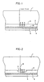
- FIG. 1 shows the structure of such an optical disc in section.
- the disc comprises a transparent substrate 1 of polycarbonate or the like, and superposed layers formed thereon, i.e., a recording layer 2 made for example of a cyanine organic dye material, a reflecting layer 3 of copper or the like, and a protective layer 4 of ultraviolet-cured resin or the like.
- Data is recorded on the disc by irradiating the disc with a laser beam B and thereby forming beam spots on the recording layer 2.
- FIG. 2 shows the disc in section after the data has been recorded thereon.
- the recording layer 2 is decomposed by being exposed to the laser beam, and a pit 5 is formed at the interface between the substrate 1 and the recording layer 2 by pressure acting on the interface.
- Such pits 5 are formed discretely with varying lengths at varying intervals along a spiral track as in the case of compact discs, whereby the desired data is recorded.
- the data is reproduced by irradiating the disc with a laser beam B as shown in FIG. 2.
- the above-mentioned literature (“NIKKEI ELECTRONICS,” Jan. 23, 1989, No. 465, p. 107) describes the principle as follows.
- the portion of the recording layer 2 formed with the pit 5 has a smaller thickness than the other portion thereof which is not pitted. This creates a phase difference of light, which results in a lower reflectance of light at the recording portion. Accordingly, the data recorded can be read out by detecting the lower reflectance. This is the same as the principle on which compact discs operate which are adapted specifically for the reproduction of audio signals.
- the nonrecording portion can be given an increased reflectance of about 78%.
- the optical disc then meets the so-called "Red Book” standard for the compact disc and becomes interchangeable with the conventional compact disc.
- the nonrecording portion can be given a higher reflectance by setting the refractive index of the dye material for forming the recording layer and the thickness of the layer to optimal values but discloses nothing specifically about the method of designing such a recording layer or the structure of the layer including the thickness thereof.
- the thickness of the recording layer is selected so that a substantial anti-reflection condition, i.e. destructive interference, exists between writting light irradiated on to the recording layer and light reflected from the reflective layer through the recording layer.
- EP 376327 which is prior art under Art 54(3) EPC, shows an optical recording medium and system similar to the invention. However, this document does not show the general teaching of the invention.
- the thickness of the recording layer and the reflectance of light on the surface of the recording layer, and found that the thickness, at which the reflectance of light becomes maximum or minimum, relates to factors such as complex indexes of refraction of the recording layer and the reflecting layer.
- the present invention which provides the recording layer with an optimal thickness based on the relationship.
- the reflectance of the surface of the recording layer varies periodically with the variation in the thickness of the recording layer and exhibits maximum values (local maximum values) and minimum values (local minimum values).
- the thickness of the recording layer in an unrecorded state is set to a value at which the reflectance comes to a maximum value or to a value approximate thereto, based on this relationship.
- the reflectance of the recording portion of the recording layer greatly decreases from the initial value. This gives a sufficiently increased modulation degree of reflected light for the subsequent reproduction of the data.
- the thickness of the recording layer in an unrecorded state is set to a predetermined value at which the reflectance of light at the surface of the recording layer comes to a maximum value or to a value approximate thereto, and the power and like irradiation conditions of the light beam for recording data are so set as to give the pitted portions of the recording layer a predetermined thickness at which the reflectance of light at the surface of the recording layer comes to a minimum value or to a value approximate thereto.
- the system maximizes the difference in the reflectance of light between the data recording portions of the recording layer and the nonrecording portion thereof to result in a sufficiently increased modulation degree of light for the reproduction of the data.
- a laser beam B is projected on an assembly of three media 6, 7 and 8 arranged in superposed layers and different in refractive index.
- the reflection of the beam will be considered.
- the beam B propagating through the first medium 6 toward the second medium 7 is partly reflected at the first interface 61 between the two media 6 and 7 as indicated at B 1 , and the remaining portion of the beam is transmitted through the interface 61 as indicated in a broken line.
- the transmitted beam is further similarly reflected at and transmitted through the second interface 71 between the second medium 7 and the third medium 8.
- the beam portion reflected at the second interface 71 is further reflected at and transmitted through the first interface 61.
- the beam reflected from the first interface 61 is one composed of the beam B 1 reflected at this interface first and the beam B 2 transmitted from the second medium 7 through the first interface 61 as described above.
- the transmitted beam B 2 includes a beam reflected at the interfaces 61, 71 a plurality of times and thereafter transmitted through the first interface 61.
- the overall reflectance coefficient (ratio in electric field amplitude between incident light and reflected light) at the first interface 61 needs to be determined with both the beams B 1 and B 2 considered, and is expressed by the following equation as is already known.
- r * r 1 + r 2 ⁇ exp - i ⁇ 1 + r 1 ⁇ r 2 ⁇ exp - i ⁇
- r 1 is the reflectance coefficient of the first interface 61 for the light propagating through the first medium 6
- r 2 is the reflectance coefficient of the second interface 71 for the light propagating through the second medium 7.
- Equation (1) 4 ⁇ ⁇ nd ⁇
- ⁇ is the wavelength of the laser beam
- n and d are the refractive index and thickness of the second medium 7.
- the first medium 6 corresponds to the transparent substrate 1
- the second medium 7 to the recording layer 2
- the third medium 8 to the reflecting layer 3.
- the refractive indexes of the substrate 1 and the recording layers 2 are n 0 , n 1 , respectively, the imaginary component (hereinafter referred to as the "extinction coefficient") of the complex index of refraction of the recording layer 2 is k 1 , the refractive index of the reflecting layer 3 is n 2 , and the extinction coefficient of the reflecting layer 3 is k 2 .
- the reflectance coefficient r 1 at the first interface 11 between the substrate 1 and the recording layer 2 and the reflectance coefficient r 2 at the second interface 21 between the recording layer 2 and the reflecting layer 3 are then expressed by Equations (3) and (4), respectively, given below.
- Equation (10) is a factor due to the phase difference.
- Equation (3) the reflectance coefficient at the first interface 11 will be expressed as follows.
- r * r 1 + r 2 ⁇ exp - 4 ⁇ ⁇ d ⁇ k 1 / ⁇ ⁇ exp - i ⁇ 4 ⁇ ⁇ d ⁇ n 1 / ⁇ 1 + r 1 ⁇ r 2 ⁇ exp - 4 ⁇ ⁇ d ⁇ k 1 / ⁇ ⁇ exp - i ⁇ 4 ⁇ ⁇ d ⁇ n 1 / ⁇
- FIG. 3 is a graph representing the reflectance R of Equation (12).
- the graph shows that the reflectance varies periodically with the variation in the thickness of the recording layer and has maximum values and minimum vales.
- d 1 ⁇ 4 ⁇ ⁇ ⁇ n 1 m + 1 ⁇ ⁇ + ⁇ 1 + ⁇ 2
- m is an integer giving positive d 1 and d 2 values.
- the reflectance of the nonrecording portion can be maximized, while the reflectance of the recording portions produced by exposure to the laser beam can be made smaller than the reflectance of the non-recording portion.
- the intensity of the laser beam for data recording is set to a suitable value so as to approximate the thickness of the pitted recording portions to the value d 1 to the greatest possible extent, whereby the difference in reflectance between the recording portions and the nonrecording portion can be maximized to fully increase the modulation degree of reflected light for the reproduction of the data.
- data can be recorded and reproduced by providing a difference in reflectance between the recording portions of the recording layer 2 and the nonrecording portion thereof.
- the reflectance of the recording layer 2 in an unrecorded state is set to a maximum, and the recording portions of the layer 2 are reduced in reflectance by irradiation with the laser beam as indicated by the arrow X in FIG. 3.
- the thicknesses d 1 and d 2 of the recording layer 2 corresponding to a minimum and a maximum of the reflectance, respectively, are calculated from the following equations, like Equations (13), (14).
- d 1 ⁇ 4 ⁇ ⁇ n 1 m + 1 ⁇ ⁇ + ⁇ 1 + ⁇ 2
- d 2 ⁇ 4 ⁇ ⁇ ⁇ n 1 m ⁇ + ⁇ 1 + ⁇ 2
- the difference in reflectance before and after data recording may be set within the range which is represented by a middle straight-line segment S - P of a maximum-to-minimum portion of the reflectance characteristics curve in FIG. 3 and which is away from the maximum and the minimum. This also affords a sufficient reflectance difference due to a small difference in the thickness of the recording layer.
- the optical discs used for experiments were each prepared with use of a polycarbonate substrate having a refractive index n 0 of 1.5 and serving as the transparent substrate 1 shown in FIG. 1, by coating the surface of the substrate 1 with a cyanine dye, 4.5 in refractive index n 1 and 0.2 in extinction coefficient k 1 , by spin coating to a specified thickness as will be stated below, and further depositing copper, 0.17 in refractive index n 2 and 4.84 in extinction coefficient k 2 , on the surface of the resulting recording layer 2 by vacuum evaporation to form a film having a thickness of 100 nm and serving as the reflecting layer 3.
- FIG. 4 is a graph showing the measurements obtained.
- the laser beam used for recording data was 0.78 ⁇ m in wavelength ⁇ .
- the graph of FIG. 4 reveals that the reflectance varies with the variation in the thickness of the recording layer and exhibits a minimum and a maximum. This tendency is in conformity with the graph of FIG. 3.
- the experimental result indicates that the thicknesses d 1 and d 2 corresponding to the minimum and the maximum of the reflectance are 26 nm and 72 nm, which are approximate respectively to 32 nm and 75 nm calculated from the foregoing theoretical equations, i.e., Equations (13), (14). This justifies the theoretical analysis described above.
- FIG. 5 is a graph showing the result of this experiment.
- the graph shows that as the power of the laser beam increases, the reflectance gradually decreases from about 90%, consequently exhibiting a minimum of about 46% at a power value of about 8 mw.
- the experimental result shown in FIG. 4 reveals that as the thickness of the recording layer decreases from about 72 nm to about 26 nm, the reflectance gradually decreases from about 90% to about 40%.
- the variation in the reflectance shows the same tendency as the experimental result given in FIG. 4.
- this is attributable to the fact that as the power of the laser beam increases, the recording layer decomposes to a greater extent, increasing the depth of the pit and reducing the thickness of the recording portion of the layer. Accordingly it is thought that the experiment shown in FIG. 5 reduced the thickness of the recording portion of the layer to about 26 nm by the projection of the laser beam with power of 8 mw.
- FIG. 6 is a graph showing the experimental result, revealing the same tendency as FIG. 3 or 5.
- the power value of the laser beam at which the reflectance is minimum is 20 mw, which is greater than the corresponding value of 8 mw in FIG. 5. This appears attributable to the fact that the recording layer 2 has a larger thickness and therefore a greater thermal capacity and rises in temperature at a lower rate.
- FIG. 7 is a graph showing the result of one of the experiments.
- the reflectance steadily increases with decreasing thickness of the recording layer, thus exhibiting no periodical variation. This case can therefore be utilized only for data recording media which are based on the principle of increasing the reflectance by decreasing the thickness of the recording layer.
- the rate of variation in the reflectance decreases as the thickness of the recording layer increases, so that the recording layer in an unrecorded state preferably has a thickness of smaller than 100 nm.
- FIG. 8 shows the result of the other experiment which was conducted by varying the power of laser beam under the same conditions as in the experiment of FIG. 7 and using three kinds of discs wherein the recording layer 2 was 50 nm, 100 nm or 210 nm in thickness.
- the graph shows that when the thickness of the recording layer is 50 nm or 100 nm, the same reflectance characteristics as shown in FIG. 7 can be obtained, whereas in the case where the thickness is 210 nm, the reflectance exhibits little or no variation.
- the experimental result therefore also indicates that it is desirable to make the thickness of the recording layer in an unrecorded state smaller than 100 nm.
- the dye material for forming the recording layer have the greatest possible refractive index.
- the reflectance then periodically varies with the thickness of the recording layer as seen in FIGS. 3 and 4.
- the thickness of the recording layer in an unrecorded state is set to d 2 at which the reflectance is locally maximum or to a smaller value.
- the reflectance can then be greatly decreased (as indicated by the arrow X in FIG. 3) by subsequently recording data on the layer to increase the modulation degree of reflected light.
- the periodical variation of the reflectance shown in FIGS. 3 and 4 can also be utilized.
- the thickness of the recording layer in an unrecorded state is set to d 1 at which the reflectance is locally minimum.
- the reflectance can then be greatly increased (as indicated by the arrow Y in FIG. 3) by subsequent data recording to increase the modulation degree of reflected light.
- the refractive index of the dye material for forming the recording layer can be smaller to some extent, but the initial thickness of the recording layer needs to be set to the smallest possible value.
- the materials for forming the component layers of the optical recording medium of FIG. 1 are not limited to those described above.
- the substrate 1 can be prepared from acrylic resin, PMMA (epoxy resin), polymer alloy produced from a mixture of polycarbonate and polystyrene, etc. Phthalocyanine dyes, naphthalocyanine dyes, polymethine dyes, etc. are usable for the recording layer 2.
- the reflecting layer 3 can be prepared from metals which are sufficiently greater than the recording layer 2 in extinction coefficient and sufficiently smaller than the recording layer 2 in refractive index, such as gold and silver. SiO 2 and the like can be used for the protective layer 4.
- optical recording medium of the present invention can be embodied not only as an optical disc but also as an optical tape.
Landscapes
- Optical Record Carriers And Manufacture Thereof (AREA)
- Manufacturing Optical Record Carriers (AREA)
- Optical Recording Or Reproduction (AREA)
Claims (4)
- Optisches Aufzeichnungsmedium mit einer lichtdurchlässigen Aufzeichnungsschicht (2), einer Reflexionsschicht (3), die auf der Rückfläche der Aufzeichnungsschicht (2) ausgebildet ist, und einem transparenten Substrat (1), das an der Vorderseite der Aufzeichnungsschicht angeordnet ist, wobei die Aufzeichnungsschicht (2) durch lokales Bestrahlen mit einem Lichtstrahl von ihrer Vorderfläche durch das transparente Substrat und dadurch einer Dickenreduktion zur Ausbildung von Pits Daten speichern kann, wobei das durch das transparente Substrat gestrahlte Licht teilweise an der Grenze (11) des Substrats (1) und der Aufzeichnungsschicht (2) und teilweise an der Grenze (21) der Aufzeichnungsschicht (2) und der Reflexionsschicht (3) reflektiert wird,
dadurch gekennzeichnet, dass der Reflexionsgrad des Aufzeichnungsmediums, der durch diese Reflexionen resultiert, eine Funktion der Dicke (d) der Aufzeichnungsschicht (2) ist und Maxima und Minima bei vorgegebenen Werten der Dicke (d) aufweist,
und dass die Dicke (d) der Aufzeichnungsschicht im Nichtaufzeichnungszustand auf einen vorgegebenen Wert eingestellt wird, bei dem der Reflexionsgrad ein Maximum ist, wobei eine Dicke (d2), die den maximalen Reflexionsgrad ergibt, durch die folgende Gleichung ausgedrückt ist:
wobei δ1, δ2, (m+1)π in Kreisgrad sind, λ eine Wellenlänge des Laserstrahls und 0,78 µm ist, n0 ein Brechungsindex des Substrats (1) bi der Wellenlänge λ ist und m eine ganze Zahl ist, die einen positiven Wert für d2 gibt, und m auf den kleinstmöglichen Wert eingestellt ist, und der Extinktionskoeffizient (k2) der Reflexionsschicht (3) bei einer Wellenlänge λ größer als (k1) der Aufzeichnungsschicht (2) bei der Wellenlänge λ ist, und dass der Brechungsindex (n2) der Reflexionsschicht (3) bei der Wellenlänge λ kleiner als (n1) der Aufzeichnungsschicht (2) bei der Wellenlänge λ ist, aber nicht enthält die Bedingung, dass das Substrat aus Polycarbonat besteht, die Reflexionsschicht aus Gold besteht und die Aufzeichnungsschicht optische Charakteristika von n1 = 2,4, k1 = 0,05 hat, und die Dicke der Aufzeichnungsschicht d2 = 140 nm ist, wobei alle Merkmale der ausschließenden Bedingung gleichzeitig erfüllt sein müssen, auch nicht enthält die Bedingung, dass das Substrat aus Polycarbonat besteht, die Reflexionsschicht aus Gold besteht und die Aufzeichnungsschicht optische Charakteristika von n1 = 2,45, k1 = 0,06 hat, und die Dicke der Aufzeichnungsschicht d2 = 140 nm ist, wobei alle Merkmale der ausschließenden Bedingung gleichzeitig erfüllt sein müssen, und auch nicht enthält die Bedingung, dass das Substrat aus Polycarbonat besteht, die Reflexionsschicht aus Gold besteht, und die Aufzeichnungsschicht optische Charakteristika von n1 = 2,35, k1 = 0,08 hat, und die Dicke der Aufzeichnungsschicht d2 = 140 nm ist, wobei alle Merkmale der ausschließenden Bedingung gleichzeitig erfüllt sein müssen. - Optisches Aufzeichnungsmedium nach Anspruch 1, wobei die Dicke der aufgezeichneten Teile der Aufzeichnungsschicht (2) auf einen vorgegebenen Wert eingestellt ist, bei dem der Reflexionsgrad ein Minimum ist, eine Dicke (d1), die einen minimalen Reflexionsgrad ergibt, durch die folgende Gleichung ausgedrückt ist:

wobei mπ in Kreisgrad ist. - System mit einem Wiedergabegerät mit einem Wiedergabelichtstrahl und einem optischen Aufzeichnungsmedium, wobei das optische Aufzeichnungsmedium eine lichtdurchlässige Aufzeichnungsschicht (2), eine Reflexionsschicht (3), die auf der Rückfläche der Aufzeichnungsschicht (2) ausgebildet ist, und ein transparentes Substrat (1) aufweist, das auf der Vorderseite der Aufzeichnungsschicht (2) ausgebildet ist, wobei die Aufzeichnungsschicht (2) durch lokales Bestrahlen mit einem Lichtstrahl auf ihre Vorderfläche durch das transparente Substrat und dabei durch eine Dickenreduktion zur Ausbildung von Pits Daten aufzeichnen kann, wobei das durch das transparente Substrat (1) eingestrahlte Licht teilweise an der Grenze (11) des Substrats (1) und der Aufzeichnungsschicht (2) und teilweise an der Grenze (21) der Aufzeichnungsschicht (2) und der Reflexionsschicht (3) reflektiert wird,
dadurch gekennzeichnet, dass der Reflexionsgrad des Aufzeichnungsmediums, der aus disen Reflexionen resultiert, eine Funktion der Dicke (d) der Aufzeichnungsschicht (2) ist, die bei vorbestimmten Werten der Dicke (d) Maxima hat, und dass die Dicke (d) der Aufzeichnungsschicht im Nichtaufzeichnungszustand auf einen vorgegebenen Wert eingestellt ist, bei dem der Reflexionsgrad ein Maximum ist, wobei eine Dicke (d2), die einen maximalen Reflexionsgrad ergibt, durch die folgenden Gleichungen ausgedrückt ist:
wobei δ1, δ2, (m + 1) π in Kreisgrad sind, λ eine Wellenlänge des Laserstrahls ist und λ gleich 0,78 µm ist, n0 ein Brechungsindex des Substrats (1) bei der Wellenlänge λ ist, und m eine ganze Zahl ist, die einen positiven Wert d2 ergibt, und m auf den kleinstmöglichen Wert gesetzt ist, und der Extinktionskoeffizient (k2) der Reflexionsschicht (3) bei einer Wellenlänge λ größer als (k1) der Aufzeichnungsschicht (2) bei der Wellenlänge λ ist, und dass der Brechungsindex (n2) der Reflexionsschicht (3) bei der Wellenlänge λ kleiner als (n1) der Aufzeichnungsschicht (2) bei der Wellenlänge λ ist, aber nicht enthält die Bedingung, dass das Substrat aus Polycarbonat besteht, die Reflexionsschicht aus Gold besteht, und die Aufzeichnungsschicht optische Charakteristika von n1 = 2,4, k1 = 0,05 hat, und die Dicke der Aufzeichnungsschicht d2 = 140 nm ist, wobei alle Merkmale der ausschließenden Bedingung gleichzeitig erfüllt sein müssen, ebenfalls nicht enthält die Bedingung, dass das Substrat aus Polycarbonat besteht, die Reflexionsschicht aus Gold besteht, und die Aufzeichnungsschicht optische Charakteristika von n1 = 2,45, k1 = 0,06 hat, und die Dicke der Aufzeichnungsschicht d2 = 140 nm ist, wobei alle Merkmale der ausschließenden Bedingung gleichzeitig erfüllt sein müssen, und auch nicht enthält die Bedingung, dass das Substrat aus Polycarbonat besteht, die Reflexionsschicht aus Gold besteht, und die Aufzeichnungsschicht optische Charakteristika von n1 = 2,35, k1 = 0,08 hat, und die Dicke der Aufzeichnungsschicht gleich d2 = 140 nm ist, wobei alle Merkmale der ausschließenden Bedingung gleichzeitig erfüllt sein müssen. - System nach Anspruch 3, wobei das Aufzeichnungsmedium mit einem Wiedergabelichtstrahl der Wellenlänge von 0,78 µm bestrahlt wird, der Brechungsindex (n0) des transparenten Substrats (1) ungefähr 1,5 beträgt, der Brechungsindex (n2) der Reflexionsschicht (3) ungefähr 0,17 beträgt, und der Brechungsindex (n1) der Aufzeichnungsschicht (2) größer als 2 ist, und die Dicke der aufgezeichneten Teile der Aufzeichnungsschicht 2 auf einen vorbestimmten Wert gesetzt ist, bei dem der Reflexionsgrad ein Minimum ist, wobei eine Dicke (d1), die den minimalen Reflexionsgrad ergibt, durch die folgende Gleichung ausgedrückt ist:

wobei mπ in Kreisgrad ist.
Applications Claiming Priority (2)
| Application Number | Priority Date | Filing Date | Title |
|---|---|---|---|
| JP123915/89 | 1989-05-17 | ||
| JP1123915A JPH0823939B2 (ja) | 1989-05-17 | 1989-05-17 | 光記録媒体とその製造方法 |
Publications (4)
| Publication Number | Publication Date |
|---|---|
| EP0398255A2 EP0398255A2 (de) | 1990-11-22 |
| EP0398255A3 EP0398255A3 (de) | 1991-06-26 |
| EP0398255B1 EP0398255B1 (de) | 1997-07-30 |
| EP0398255B2 true EP0398255B2 (de) | 2007-09-26 |
Family
ID=14872495
Family Applications (1)
| Application Number | Title | Priority Date | Filing Date |
|---|---|---|---|
| EP19900109147 Expired - Lifetime EP0398255B2 (de) | 1989-05-17 | 1990-05-15 | Optischer Aufzeichnungsträger und System bestehend aus einem Wiedergabegerät und einem solchen Aufzeichnungsträger |
Country Status (3)
| Country | Link |
|---|---|
| EP (1) | EP0398255B2 (de) |
| JP (1) | JPH0823939B2 (de) |
| DE (1) | DE69031147T3 (de) |
Families Citing this family (2)
| Publication number | Priority date | Publication date | Assignee | Title |
|---|---|---|---|---|
| JP3400832B2 (ja) * | 1992-12-03 | 2003-04-28 | 株式会社日立製作所 | 情報記録媒体およびこれを用いた情報記録再生システム |
| US8859184B2 (en) * | 2005-07-28 | 2014-10-14 | Ricoh Company, Ltd. | Write-once-read-many optical disk having low-to-high recording property accommodating short wavelength recording |
Family Cites Families (4)
| Publication number | Priority date | Publication date | Assignee | Title |
|---|---|---|---|---|
| US4305081A (en) * | 1976-03-19 | 1981-12-08 | Rca Corporation | Multilayer record blank for use in optical recording |
| DE3482147D1 (de) * | 1983-06-27 | 1990-06-07 | Optical Disc Corp | Optisches duennfilm-aufzeichnungsmedium mit hohem kontrast. |
| DE3884662T2 (de) * | 1987-05-08 | 1994-03-03 | Toshiba Kawasaki Kk | Medium für Informationsspeicherung. |
| JP2899008B2 (ja) * | 1989-03-07 | 1999-06-02 | 富士写真フイルム株式会社 | 情報記録媒体 |
-
1989
- 1989-05-17 JP JP1123915A patent/JPH0823939B2/ja not_active Expired - Lifetime
-
1990
- 1990-05-15 DE DE1990631147 patent/DE69031147T3/de not_active Expired - Fee Related
- 1990-05-15 EP EP19900109147 patent/EP0398255B2/de not_active Expired - Lifetime
Also Published As
| Publication number | Publication date |
|---|---|
| EP0398255A2 (de) | 1990-11-22 |
| EP0398255A3 (de) | 1991-06-26 |
| DE69031147T2 (de) | 1998-02-26 |
| JPH02302943A (ja) | 1990-12-14 |
| DE69031147T3 (de) | 2008-04-30 |
| JPH0823939B2 (ja) | 1996-03-06 |
| EP0398255B1 (de) | 1997-07-30 |
| DE69031147D1 (de) | 1997-09-04 |
Similar Documents
| Publication | Publication Date | Title |
|---|---|---|
| CA1190276A (en) | Thermo-optical method for writing information and an information medium for the application of said method | |
| EP0319037B1 (de) | Optisches Informationsaufzeichnungsmedium | |
| US5144618A (en) | Optical disc medium | |
| EP0092113B1 (de) | Optisches Speicherelement zur Verwendung in einem optischen Speichersystem sowie ein Verfahren zur Herstellung des Speicherelements | |
| US5410534A (en) | Optical information recording medium | |
| EP0045806A1 (de) | Optische echtzeit-scheibe und verfahren zum aufzeichnen und ablesen. | |
| CN100416682C (zh) | 光学信息媒体 | |
| EP0564260B1 (de) | Optisches Aufzeichnungsmedium und optisches Aufzeichnungs/Wiedergabegerät | |
| US5449589A (en) | Method of making an optical information recording medium and method of recording/reproducing optical information | |
| EP0398255B2 (de) | Optischer Aufzeichnungsträger und System bestehend aus einem Wiedergabegerät und einem solchen Aufzeichnungsträger | |
| JPH052771A (ja) | 光記録媒体 | |
| JP3287860B2 (ja) | 光学的情報記録方法と記録媒体 | |
| EP1515322B1 (de) | Optisches aufzeichnungsmedium, optischer informationsprozessor und optisches aufzeichnungs-/wiedergabeverfahren | |
| JP3041388B2 (ja) | 光情報記録媒体及び光情報記録媒体用スタンパの原盤製造方法 | |
| KR100292378B1 (ko) | 기록/재생 가능한 광기록 매체 및 그에 대한 광기록 방법 | |
| JP2001189033A (ja) | 光記録媒体 | |
| JP2001273679A (ja) | 光記録媒体 | |
| JP2002109786A (ja) | 光記録媒体 | |
| JPH0573955A (ja) | 光学的記録媒体円盤 | |
| JPS61130094A (ja) | 情報記録媒体及び記録再生方法 | |
| JP2596477B2 (ja) | 光情報記録媒体 | |
| JP2004109871A (ja) | 光記録型積層導波路ホログラム媒体、ホログラム記録方法およびホログラム再生方法 | |
| EP0473709A1 (de) | Wechselwirkende optische scheibe und systeme und methoden zur verwendung dergleichen | |
| JPH04286734A (ja) | 光情報記録媒体 | |
| KR100207581B1 (ko) | 광기록매체 |
Legal Events
| Date | Code | Title | Description |
|---|---|---|---|
| PUAI | Public reference made under article 153(3) epc to a published international application that has entered the european phase |
Free format text: ORIGINAL CODE: 0009012 |
|
| AK | Designated contracting states |
Kind code of ref document: A2 Designated state(s): DE FR GB |
|
| PUAL | Search report despatched |
Free format text: ORIGINAL CODE: 0009013 |
|
| AK | Designated contracting states |
Kind code of ref document: A3 Designated state(s): DE FR GB |
|
| 17P | Request for examination filed |
Effective date: 19911217 |
|
| 17Q | First examination report despatched |
Effective date: 19931203 |
|
| GRAG | Despatch of communication of intention to grant |
Free format text: ORIGINAL CODE: EPIDOS AGRA |
|
| GRAH | Despatch of communication of intention to grant a patent |
Free format text: ORIGINAL CODE: EPIDOS IGRA |
|
| RAP1 | Party data changed (applicant data changed or rights of an application transferred) |
Owner name: SANYO ELECTRIC CO., LTD. |
|
| GRAH | Despatch of communication of intention to grant a patent |
Free format text: ORIGINAL CODE: EPIDOS IGRA |
|
| GRAA | (expected) grant |
Free format text: ORIGINAL CODE: 0009210 |
|
| AK | Designated contracting states |
Kind code of ref document: B1 Designated state(s): DE FR GB |
|
| ET | Fr: translation filed | ||
| REF | Corresponds to: |
Ref document number: 69031147 Country of ref document: DE Date of ref document: 19970904 |
|
| PLBI | Opposition filed |
Free format text: ORIGINAL CODE: 0009260 |
|
| PLBF | Reply of patent proprietor to notice(s) of opposition |
Free format text: ORIGINAL CODE: EPIDOS OBSO |
|
| 26 | Opposition filed |
Opponent name: AKZO NOBEL N.V. Effective date: 19980420 |
|
| PLBF | Reply of patent proprietor to notice(s) of opposition |
Free format text: ORIGINAL CODE: EPIDOS OBSO |
|
| PLBF | Reply of patent proprietor to notice(s) of opposition |
Free format text: ORIGINAL CODE: EPIDOS OBSO |
|
| RDAH | Patent revoked |
Free format text: ORIGINAL CODE: EPIDOS REVO |
|
| APAC | Appeal dossier modified |
Free format text: ORIGINAL CODE: EPIDOS NOAPO |
|
| APAE | Appeal reference modified |
Free format text: ORIGINAL CODE: EPIDOS REFNO |
|
| APAC | Appeal dossier modified |
Free format text: ORIGINAL CODE: EPIDOS NOAPO |
|
| REG | Reference to a national code |
Ref country code: GB Ref legal event code: IF02 |
|
| APBY | Invitation to file observations in appeal sent |
Free format text: ORIGINAL CODE: EPIDOSNOBA2O |
|
| APBY | Invitation to file observations in appeal sent |
Free format text: ORIGINAL CODE: EPIDOSNOBA2O |
|
| APBY | Invitation to file observations in appeal sent |
Free format text: ORIGINAL CODE: EPIDOSNOBA2O |
|
| APAH | Appeal reference modified |
Free format text: ORIGINAL CODE: EPIDOSCREFNO |
|
| APBU | Appeal procedure closed |
Free format text: ORIGINAL CODE: EPIDOSNNOA9O |
|
| PUAH | Patent maintained in amended form |
Free format text: ORIGINAL CODE: 0009272 |
|
| STAA | Information on the status of an ep patent application or granted ep patent |
Free format text: STATUS: PATENT MAINTAINED AS AMENDED |
|
| 27A | Patent maintained in amended form |
Effective date: 20070926 |
|
| AK | Designated contracting states |
Kind code of ref document: B2 Designated state(s): DE FR GB |
|
| ET3 | Fr: translation filed ** decision concerning opposition | ||
| PGFP | Annual fee paid to national office [announced via postgrant information from national office to epo] |
Ref country code: DE Payment date: 20080522 Year of fee payment: 19 |
|
| PGFP | Annual fee paid to national office [announced via postgrant information from national office to epo] |
Ref country code: GB Payment date: 20080521 Year of fee payment: 19 |
|
| GBPC | Gb: european patent ceased through non-payment of renewal fee |
Effective date: 20090515 |
|
| REG | Reference to a national code |
Ref country code: FR Ref legal event code: ST Effective date: 20100129 |
|
| PG25 | Lapsed in a contracting state [announced via postgrant information from national office to epo] |
Ref country code: FR Free format text: LAPSE BECAUSE OF NON-PAYMENT OF DUE FEES Effective date: 20090602 |
|
| PGFP | Annual fee paid to national office [announced via postgrant information from national office to epo] |
Ref country code: FR Payment date: 20080514 Year of fee payment: 19 |
|
| PG25 | Lapsed in a contracting state [announced via postgrant information from national office to epo] |
Ref country code: GB Free format text: LAPSE BECAUSE OF NON-PAYMENT OF DUE FEES Effective date: 20090515 |
|
| PG25 | Lapsed in a contracting state [announced via postgrant information from national office to epo] |
Ref country code: DE Free format text: LAPSE BECAUSE OF NON-PAYMENT OF DUE FEES Effective date: 20091201 |