EP0398280A2 - Universal-Biegewerkzeug - Google Patents
Universal-Biegewerkzeug Download PDFInfo
- Publication number
- EP0398280A2 EP0398280A2 EP90109222A EP90109222A EP0398280A2 EP 0398280 A2 EP0398280 A2 EP 0398280A2 EP 90109222 A EP90109222 A EP 90109222A EP 90109222 A EP90109222 A EP 90109222A EP 0398280 A2 EP0398280 A2 EP 0398280A2
- Authority
- EP
- European Patent Office
- Prior art keywords
- profile
- carrier
- bending
- base plate
- bending tool
- Prior art date
- Legal status (The legal status is an assumption and is not a legal conclusion. Google has not performed a legal analysis and makes no representation as to the accuracy of the status listed.)
- Granted
Links
- 238000005452 bending Methods 0.000 title claims abstract description 103
- 210000000078 claw Anatomy 0.000 claims description 4
- 239000000969 carrier Substances 0.000 description 17
- 238000012937 correction Methods 0.000 description 4
- 238000000034 method Methods 0.000 description 4
- 239000000463 material Substances 0.000 description 3
- 238000003466 welding Methods 0.000 description 3
- 229920001817 Agar Polymers 0.000 description 1
- 238000005553 drilling Methods 0.000 description 1
- 239000002184 metal Substances 0.000 description 1
- 230000000284 resting effect Effects 0.000 description 1
Images



Classifications
-
- B—PERFORMING OPERATIONS; TRANSPORTING
- B21—MECHANICAL METAL-WORKING WITHOUT ESSENTIALLY REMOVING MATERIAL; PUNCHING METAL
- B21D—WORKING OR PROCESSING OF SHEET METAL OR METAL TUBES, RODS OR PROFILES WITHOUT ESSENTIALLY REMOVING MATERIAL; PUNCHING METAL
- B21D7/00—Bending rods, profiles, or tubes
- B21D7/06—Bending rods, profiles, or tubes in press brakes or between rams and anvils or abutments; Pliers with forming dies
Definitions
- the invention relates to a universal bending tool consisting of a base plate with a mold carrier arranged on the base plate on bracket supports in accordance with the contour and shape plane of the profile to be bent, the profile to be bent being bent in the manner of a bending template around a profile carrier projecting from the mold carrier by means of form rollers becomes.
- Bending tools of this type are used for the bending technique of metal profiles, a profile to be bent being bent on a bending tool around a bending template.
- the bending tool itself essentially consists of a base plate, to which triangular bracket supports are welded, which carry a mold carrier that is perpendicular to the base plate, and furthermore the bending template itself is now applied to the mold carrier in the manner of a profile carrier by welding or other fastening means .
- the present invention is therefore based on the object of developing a bending tool of the type mentioned in such a way that it is suitable for universal bending work can be used without the need to laboriously change the entire tool when using a new bending template.
- bracket supports are arranged in an adjustable and adjustable manner and, furthermore, tensioning elements are provided on the bracket supports, which tension the mold support and at the same time carry the profile support and are adjustable in height as desired.
- a universally usable bending tool is created in that several individual, parallel to each other and mutually adjustable bracket supports are arranged on a base plate, wherein each bracket support clamping elements are arranged which carry the bending template.
- the profile to be bent is bent over the bending template.
- the bending process is carried out in the form of stretch bending by using a straight profile bar under tensile stress and high contact pressure, e.g. is generated via bending rollers, is drawn over the bending template.
- stretch bending there is also an unroll stretch bending and the like.
- Such bending processes are described in detail in earlier U.S. patents by the same inventor. Reference is made to the revelation there. This disclosure is intended to be fully encompassed by the present invention.
- clamping elements are now arranged on the mold carriers, which define support surfaces, the clamping elements being arranged opposite one another on the mold carriers and defining an intermediate space between them, into which the bending template is clamped.
- the clamping elements on the top and bottom then support themselves with their support surfaces on the top and bottom sides of the bending template and thus fix the bending template in all three room levels.
- the clamping elements are easily adjustable on the Shape carriers are held, and it is therefore possible to first set up the bending template so that it corresponds exactly to the required bending of the profile. Once the bending template has been set up, the tensioning elements are braced against one another in order to fix the bending template.
- the clamping takes place in such a way that the clamping elements are first rotated, the support surface on the bending template being eccentric to the pivot point of the clamping elements on the mold carrier, so that when these clamping elements are rotated on the bending template, an additional contact force is generated on the bending template.
- the tensioning elements are then braced with the bending template by means of a screw, which passes through a longitudinal bore in the upper tensioning element, crosses an aligned bore in the bending template and engages in an associated, thus aligned bore of the lower tensioning element.
- the two clamping elements lying one below the other are thus connected to each other with the bending template by means of a common screw which penetrates all three parts.
- the tensioning elements are designed as sheet-like layers which are layered in a packet-like manner and can be moved individually with respect to one another.
- clamping elements are generally referred to as mold carriers.
- the mold carriers are adjustably attached to a bracket carrier.
- bracket supports and their attachment to the base plate first determine the contour shape of the profile to be bent.
- a shape plane for the profile to be bent is thus determined by the mold carrier.
- the mold carrier can consist of one or more sheet-like layers which are layered individually and which can be displaced relative to one another, initially manually can be contoured by shifting in the plane of the base plate.
- this is omitted and the mold carriers can be contoured manually.
- mold carriers in turn carry a plastic carrier which has the task of engaging in the hollow profile of the profile to be bent and receiving this profile.
- the plastic carrier serves as a profile holder and holds the profile to be bent.
- the profile carrier preferably consists of a plastic material, so that this plastic material can be easily molded.
- clamping elements are present on the bracket supports, which clamping elements clamp the mold supports and at the same time carry the profile supports and are height-adjustable as desired.
- bracket supports are adjustably arranged on a base plate, that the bracket supports are connected to clamping elements, which clamp clamping elements form supports and at the same time carry the profile support.
- the required bending shape which can also include three-dimensional or torsional bending, is shown in the drawing, and the bending template described here is first manually set to the required bending shape.
- a sample profile is then bent and compared to the required bending shape, and due to these deviations one can see where corrections are necessary.
- This mold carrier therefore only has the task of creating a base surface for the profile carrier resting thereon, which is then arranged to be displaceable in the Z plane on the mold carrier.
- the form carrier therefore only has the task of producing the required bending contour, whereby - as stated at the beginning - the edge contour is produced by the profile cylinder.
- Bracket 2 are adjustable in the plane of the base plate 1 adjustable.
- Each bracket support 2 carries two clamping elements arranged one above the other, which define an intermediate space between them.
- Each clamping element 33 is slidably fastened by screws 34 in the region of a vertically aligned elongated hole 35 in the mold carrier 3.
- the mold carrier 3 is adjustably fastened to the console carrier 2 in two mutually perpendicular spatial axes.
- the tensioning elements each define support surfaces 40 and thus carry a bending template 36 which, in the exemplary embodiment shown (see FIG. 3), consists of two parts.
- the bending template 36 here consists of a vertical template 37 and a horizontal template 38.
- the two templates define a bending profile 39, via which a profile in the exact profile shape of the bending profile 39 is bent by means of bending rollers indicated in FIG.
- the bending template 36 thus defines the position, rotation and inclination of the bending profile 39 to be bent, while the bending profile 39 itself defines the geometric dimensions of the profile to be bent.
- the clamping elements 33 are still not tightly clamped with the bending template 36.
- the bending template 36 can first be freely bent (using tools) so that it corresponds exactly to the required bending line. According to Figure 1, the bending template 36 is only temporarily held on the clamping elements 33.
- the clamping elements are firmly connected to the bending template 36.
- the clamping elements 33 are first rotated around the bearing points in the screws 34, so that the rounded support surfaces 40 wedge with the associated surfaces of the bending template 36. This is because the support surface 30 is eccentric to the bearing point in the screw 34 of the clamping element 33.
- a screw 42 is used to connect the three parts (33 and 36).
- the screw 42 engages through the mutually aligned longitudinal bores 44 in the opposing clamping elements 33 and additionally through a bore 43 in the bending template 36.
- the bores 43, 44 are subsequently produced by simply drilling through the clamping elements aligned in FIG. 2, after which the screw 42 is then passed through and screwed. In this way, a firm and permanent connection of the tensioning elements to the bending template 36 takes place.
- a further screw 41 is screwed into the bending template 36, each of which is connected to a clamping element 33.
- Such screws 41 are arranged, for example, only in every 4th or 5th clamping element 33.
- FIGS. 4 and 5 A further embodiment of a bending tool according to the invention is explained with reference to FIGS. 4 and 5.
- bracket supports 2 are fastened to a base plate 1, with corresponding screws 7 engaging in threaded bores 8 in the base plate 1.
- Elongated holes 9 are provided in the area of the bracket supports, so that the bracket supports 2 are arranged so that they can be moved and locked on the base plate.
- Each bracket support 2 has a front plate 10, in which a plurality of receiving bores 11 are provided.
- the screw bolt 12 of a fastening screw 13 passes through each receiving bore 11, and a nut connection 14 is arranged on the rear of the front plate 10.
- mold carriers 3 which, as stated at the outset, define the bending shape.
- the mold carriers 3 have bores 15 which are penetrated by the threaded bolts 12.
- the threaded bolts carry clamping claws 16 which have fingers 17 pointing towards one another, the fingers 17 engaging in an associated groove 18 of the profiled support 4.
- the profile carrier 4 is displaceable in the Z direction, because the clamping claws 16 have elongated holes 19 aligned in the Z direction.
- the clamping claws 16 can thus be displaced in the area of the elongated holes 19, as a result of which the profile carrier 4 can thus be displaced in the Z axis.
- the profile carrier 4 has an outer profile 20 which engages in the inner profile of the profile 21 to be bent.
- the profile 21 to be bent is thus stabilized during the bending process.
- Profile rollers 22, 23 rest on the outside on the profile 21 to be bent.
- the bracket 2 are formed in two parts and consist of two parts, the front panels 10 are not fixed to the bracket, but, as shown in Figure 2, the front panels via appropriate screw connections 25 with the part 24 of Console bracket are adjustably connected.
- An angular position of the profile carrier 4 in relation to the plane of the base plate can thus be set.
- Figure 3 shows a modified embodiment where it can be seen that a profile cylinder 5 is arranged in the area of the corner, which in turn is adjustable.
- the profile cylinder 5 is arranged on a support plate 27, which is connected to the base plate 1 with corresponding screw connections 28.
- elongated holes are again arranged to ensure the adjustability of the profile cylinder 5 parallel to the plane of the base plate 1.
- a section through the profile cylinder 5 can be seen in FIG. 4.
- the profile cylinder 6 preferably consists of three parts, with a front piece 29, a profile support 30 and a chuck piece 31; all parts are connected to the carrier plate 27 by a clamping screw 32.
- clamping screw 32 extends through an elongated hole 34 in the support plate 27 so that the entire structure, consisting of the parts 29, 30, 31, can also be adjusted parallel to the base plate.
- the further screw 35 serves to fasten the profiled support formed from plastic to the outer circumference of the profiled support 4, while the screw connection 33 serves to fasten the shaped support 3 to the outer circumference of the profiled support.
- the tool can still be arranged adjustably via hydraulic or pneumatic cylinders, ie the geometry in the areas of narrow and wide radii can be changed depending on the batch difference, so that a profile retains its nominal size despite (new) strength.
- a spring-back component is thereby assigned to the tool; the sensitive adjustment takes into account different material properties of different batches.
Landscapes
- Engineering & Computer Science (AREA)
- Mechanical Engineering (AREA)
- Bending Of Plates, Rods, And Pipes (AREA)
- Forklifts And Lifting Vehicles (AREA)
- Hand Tools For Fitting Together And Separating, Or Other Hand Tools (AREA)
- Moulds For Moulding Plastics Or The Like (AREA)
Abstract
Description
- Die Erfindung betrifft ein Universal-Biegewerkzeug, bestehend aus einer Basisplatte mit einem entsprechend der Kontur und Formebene des zu biegenden Profils an der Basisplatte an Konsolträgern angeordneten Formträger, wobei das zu biegende Profil nach Art einer Biegeschablone um einen vom Formträger abragenden Profilträger herum mittels Formrollen gebogen wird.
- Derartige Biegewerkzeuge werden für die Biegetechnik von Metallprofilen eingesetzt, wobei ein zu biegendes Profil auf einem Biegewerkzeug um eine Biegeschablone herum gebogen wird. Das Biegewerkzeug selbst besteht im wesentlichen aus einer Basisplatte, an der dreieckförmige Konsolträger angeschweisst sind, welche einen Formträger tragen, der zu der Basisplatte senkrecht steht, und im weiteren ist auf dem Formträger nun die Biegeschablone selbst nach Art eines Profilträgers durch Schweissen oder andere Befestigungsmittel aufgebracht.
- Nachteil derartiger Biegewerkzeuge ist, daß sie im wesentlichen nur einmal für eine bestimmte Biegearbeit eingesetzt werden können. Sollen andere Profile gebogen werden, muß ein anderes Biegewerkzeug verwendet werden.
- Im übrigen ist ein derartiges Biegewerkzeug nur schwierig zu ändern, denn, wenn Korrekturen notwendig sind, muß die Biegeschablone, die auf der Trägerplatte befestigt ist, mit der Trennschere abgetrennt werden und nach dem Anbringen von Korrekturen muß die neue Biegeschablone wieder aufgeschweißt werden.
- Der vorliegenden Erfindung liegt deshalb die Aufgabe zugrunde, ein Biegewerkzeug der eingangs genannten Art so weiterzubilden, daß es für universelle Biegearbeiten verwendbar ist, ohne daß ein umständliches Ändern des gesamten Werkzeugs bei Verwendung einer neuen Biegeschablone notwendig wird.
- Zur Lösung der Aufgabe ist es vorgesehen, daß an der Basisplatte die Konsolträger verstellbar und einstellbar angeordnet sind und weiterhin an den Konsolträgern Spannelemente vorgesehen sind, welche den Formträger spannen und gleichzeitig den Profilträger tragen und in der Höhe beliebig verstellbar sind.
- Gemäss der vorliegenden Erfindung ist nun vorgesehen, daß ein universell einsetzbares Biegewerkzeug dadurch geschaffen wird, daß auf einer Basisplatte mehrere einzelne, parallel zueinander angeordnete und zueinander verstellbare Konsolträger angeordnet sind, wobei an jedem Konsolträger Spannelemente angeordnet sind, welche die Biegeschablone tragen. Über die Biegeschablone wird das zu biegende Profil gebogen. Das Biegeverfahren erfolgt hierbei in Form eines Streck-Biegens, indem ein gerader Profilstab unter Zugspannung und hoher Anpresskraft, die z.B. über Biegerollen erzeugt wird, über die Biegeschablone gezogen wird. Neben diesem Streck-Biegen gibt es auch ein Abroll-Streckbiegen und dergleichen mehr. Derartige Biegeverfahren sind in älteren US-Patenten des gleichen Erfinders eingehend beschrieben. Auf die dortige Offenbarung wird bezug genommen. Diese Offenbarung soll vollinhaltlich von der vorliegenden Erfindung umfasst werden.
- Erfindungsgemäss sind nun auf den Formträgern Spannelemente angeordnet, welche Stützflächen definieren, wobei die Spannelemente einander gegenüberliegend an den Formträgern angeordnet sind und zwischen sich einen Zwischenraum definieren, in den die Biegeschablone eingespannt wird. Die Spannelemente der Ober- und Unterseite stützen sich dann mit ihren Stützflächen an den Ober- und Unterseiten der Biegeschablone ab und fixieren somit die Biegeschablone in allen drei Raumebenen.
- Wichtig ist nun, daß die Spannelemente leicht verstellbar an den Formträgern gehalten sind, und es ist daher möglich, die Biegeschablone zunächst so einzurichten, daß sie genau der geforderten Biegung des Profils entspricht. Ist diese Einrichtung der Biegeschablone erfolgt, dann werden die Spannelemente gegeneinander verspannt, um so die Biegeschablone zu fixieren.
- Das Verspannen erfolgt hierbei so, daß die Spannelemente zunächst gedreht werden, wobei die Abstützfläche auf die Biegeschablone exzentrisch zu dem Drehpunkt der Spannelemente am Formträger liegt, so daß beim Verdrehen dieser Spannelemente auf der Biegeschablone eine zusätzliche Anpresskraft auf die Biegeschablone erzeugt wird. Die Verspannung der Spannelemente mit der Biegeschablone erfolgt dann über jeweils eine Schraube, welche durch eine Längsbohrung in dem oberen Spannelement hindurchgeht, eine damit fluchtende Bohrung in der Biegeschablone durchquert und in eine zugeordnete, damit fluchtende Bohrung des unteren Spannelements hindurchgreift. Die jeweils beiden untereinander liegenden Spannelemente werden also mit der Biegeschablone über eine gemeinsame - alle drei Teile durchgreifenden - Schraube miteinander verbunden.
- In einer anderen Ausführungsform sind die Spannelemente als paketförmig geschichtete, einzeln zueinander verschiebbare Bleche ausgebildet.
- Diese Spannelemente werden allgemein als Formträger bezeichnet. Die Formträger sind hierbei auf einem Konsolträger verstellbar befestigt.
- Diese Konsolträger und deren Befestigung auf der Basisplatte bestimmen zunächst einmal die Konturform des zu biegenden Profils.
- Durch den Formträger wird also eine Formebene für das zu biegende Profil bestimmt.
- Der Formträger kann aus ein oder mehreren paketförmig geschichteten, einzeln zueinander verschiebbaren Blechen bestehen, die manuell zunächst durch Verschiebung in der Ebene der Basisplatte konturiert werden können.
- Früher mußte man die bekannten Formträger mit der Trennschere abtrennen dann neu konturieren und dann wieder anschweißen.
- Nach der Erfindung entfällt dieses und die Formträger können manuell konturiert werden.
- Diese Formträger tragen ihrerseits einen Kunststoffträger der die Aufgabe hat, in das Hohlprofil des zu biegenden Profils einzugreifen und dieses Profil aufzunehmen. Der Kunststoffträger dient als Profilaufnahme und hält das zu biegende Profil.
- Bei Profilen, die z. B. in einem Winkel von 60° zueinander zu biegen sind,gibt es keinen durchgehenden Profilträger, sondern an den zu biegenden Kanten ist der Profilträger unterbrochen, und an dieser Stelle ist ein Drehteil eingesetzt, d.h. also ein Zylinder, der von der einen Seite mit seiner Mantelfläche bündig mit dem einen Profilträger und an seiner anderen Mantelfläche bündig mit dem anderen Profilträger ist und beide Profilträger an diesem Profilzylinder aufgenommen sind. Derartige Profilzylinder, welche mit den Profilträgern verbunden sind, sind also für beliebige offene und geschlossene Biegewinkel möglich.
- Wichtig ist nun, daß der Profilträger bevorzugt aus einem Kunststoffmaterial besteht, so daß eine leichte Formbarkeit dieses Kunststoffmaterials gewährleistet ist.
- Entscheidend ist nun, daß an den Konsolträgern Spannelemente vorhanden sind, welche Spannelemente die Formträger spannen und gleichzeitig den Profilträger tragen und in der Höhe beliebig verstellbar sind.
- Auf diese Weise ist es möglich, den Profilträger in der Z-Achse zu verschieben, um eine räumliche Biegung zu erreichen in Verbindung mit den Biegungen in der X- und Y-Achse.
- Der Kern der vorliegenden Erfindung liegt also darin, daß einstellbar auf einer Basisplatte Konsolträger angeordnet sind, daß die Konsolträger mit Spannelementen verbunden sind, welche Spannelemente Formträger einspannen und gleichzeitig den Profilträger tragen.
- Damit ist wird ein weitgehend universal verwendbares Biegewerkzeug beschrieben, denn durch die Einstellung der Konsolträger auf die Basisplatte kann die grobe Biegekontur vorgegeben werden und die praktische Anwendung des Biegewerkzeuges erfolgt wie folgt:
- Zunächst wird die geforderte Biegeform, die durchaus auch dreidimensional oder eine Torsionsbiegung beinhalten kann, zeichnerisch dargestellt,und die hier beschriebene Biegeschablone wird auf die geforderte Biegeform zunächst manuell eingestellt.
- Es wird dann ein Probeprofil gebogen und mit der geforderten Biegeform verglichen, und aufgrund dieser Abweichungen sieht man dann, wo Korrekturen erforderlich sind.
- Bisher konnten also manuelle Korrekuturen nur sehr aufwendig durchgeführt werden, indem man eben den Profilträger abtrennte, manuell nachbog und wieder aufschweißte oder sonstwie befestigte, ebenso mußte man die Konsolträger abtrennen und wieder aufschweißen und dgl.mehr. Es waren also in bekannter Weise viel Schweißarbeit, Abtrennarbeit, Richt - und Biegearbeit erforderlich.
- Mit der vorliegenden Erfindung sind nun verschiedene Einstellmöglichkeiten gegeben, die es erlauben, eine neuartige Biegeschablone in Minutenschnelle einem geforderten Biegeprofil anzupassen.
- Dazu sind einmal die einstellbaren Befestigungen zwischen den Konsolträgern und der Basisplatte vorhanden; ferner die einstellbaren Befestigungen zwischen den Konsolträgern und den Formträgern und ferner die einstellbare Befestigung zwischen dem Profilträger und den Formträgern.
- Statt der paketförmigen Anordnung dieser Formträger ist es selbstverständlich auch möglich, lediglich zwei Bleche oder nur ein einziges Blech zu verwenden.
- Dieser Formträger hat also nur die Aufgabe, eine Basisfläche für den darauf aufliegenden Profilträger zu schaffen, der dann in Z-Ebene auf dem Formträger verschiebbar angeordnet ist.
- Der Formträger hat also nur die Aufgabe, die geforderte Biegekontur herzustellen, wobei - wie eingangs ausgeführt - die Kantenkontur durch die Profilzylinder hergestellt wird.
- Die Erfindung wird nun anhand der Zeichnungen näher beschrieben. Hierbei ergeben sich aus der Zeichnung und ihrer Beschreibung weitere Merkmale und Vorteile der Erfindung.
- In den Zeichnungen zeigen:
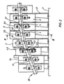
- Figur 1 Seitenansicht eines Biegewerkzeugs nach der Erfindung in einer ersten Ausführungsform mit einer noch nicht endgültig befestigten Biegeschablone,
- Figur 2 das Werkzeug nach Figur 1 mit der endgültig befestigten Biegeschablone in Gebrauchsstellung,
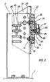
- Figur 3 Schnitt gemäss der Linie III-III in Figur 2,
- Figur 4 Seitenansicht eines Biegewerkzeuges in einer zweiten Ausführungsform mit paketförmigen Spannelementen,
- Figur 5 die Draufsicht auf das Werkzeug nach Figur 4,
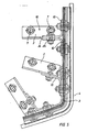
- Figur 6 eine dritte Ausführungsform eines Biegewerkzeugs nach der E findung, wo an den Kanten der Biegeschablone ein Profilzylinder angeordnet ist,
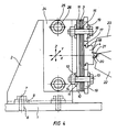
- Figur 7 der Profilzylinder nach Figur 6 im Schnitt mit Profilrollen, die an dem zu biegenden Profil anliegen.
- In Figur 1 ist dargestellt, daß auf einer Basisplatte 1 Konsolträger 2 verstellbar in der Ebene der Basisplatte 1 verstellbar sind. Jeder Konsolträger 2 trägt zwei übereinander liegend angeordnete Spannelemente, die zwischen sich einen Zwischenraum definieren. Jedes Spannelement 33 ist über Schrauben 34 verschiebbar im Bereich eines vertikal ausgerichteten Langloches 35 im Formträger 3 befestigt.
- Der Formträger 3 seinerseits ist mit dem Konsolträger 2 in zwei zueinander senkrecht stehenden Raumachsen verstellbar befestigt.
- Die Spannelemente definieren jeweils Stützflächen 40, und tragen somit eine Biegschablone 36, die im gezeigten Ausführungsbeispiel (siehe Figur 3) aus zwei Teilen besteht. Die Biegeschablone 36 besteht hierbei aus einer Vertikal-Schablone 37 und einer Horizontal-Schablone 38. Die beiden Schablonen definieren ein Biegeprofil 39, über welches mittels in Figur 3 angedeuteten Biegerollen ein Profil in der genauen Profilform des Biegeprofils 39 gebogen wird.
- Die Biegeschablone 36 definiert also die Lage, Verdrehung und Neigung des zu biegenden Biegeprofils 39, während das Biegeprofil 39 selbst die geometrischen Abmessungen des zu biegenden Profils definiert.
- In der in Figur 1 dargestellten Lage sind die Spannelemente 33 noch nicht fest mit der Biegeschablone 36 verspannt. In dieser Stellung kann zunächst die Biegeschablone 36 frei (mittels Werzeugen) so gebogen werden, daß sie genau der geforderten Biegelinie entspricht. Gemäss Figur 1 wird also die Biegeschablone 36 über die Spannelemente 33 nur vorläufig festgehalten.
- Liegt die endgültige Formgebung der Biegeschablone 36 fest, dann werden die Spannelemente fest mit der Biegeschablone 36 verbunden. Hierzu werden zunächst einmal die Spannelemente 33 um die Lagerpunkte in den Schrauben 34 gedreht, so daß sich die abgerundeten Stützflächen 40 mit den zugeordneten Flächen der Biegeschablone 36 verkeilen. Dies liegt daran, daß die Stützfläche 30 exzentrisch zu dem Lagerpunkt in der Schraube 34 des Spannelements 33 liegt.
- Wenn alle Spannelemente 33 gemäss Figur 2 durch Verdrehen mit der Biegeschablone 36 verspannt wurden, wird eine Schraube 42 zur Verbindung der drei Teile (33 und 36) verwendet. Die Schraube 42 greift hierbei durch die zueinander fluchtenden Längsbohrungen 44 in den einander gegenüberliegenden Spannelementen 33 und zusätzlich durch eine Bohrung 43 in der Biegeschablone 36.
- Die Bohrungen 43,44 werden nachträglich durch einfaches Durchbohren der in Figur 2 ausgerichteten Spannelemente hergestellt, wonach dann die Schraube 42 hindurchgeführt und verschraubt wird. Auf diese Weise erfolgt eine feste und unlösbare Verbindung der Spannelemente mit der Biegeschablone 36.
- Zur zusätzlichen Befestigung der Biegeschablone in einer zur Schraube 42 senkrechten Richtung ist es noch vorgesehen, daß in die Biegeschablone 36 noch eine weitere Schraube 41 eingeschraubt ist, die jeweils mit einem Spannelement 33 verbunden ist.
- Derartige Schrauben 41 sind beispielsweise nur in jedem 4. oder 5. Spannelement 33 angeordnet.
- Anhand der Figuren 4 und 5 wird eine weitere Ausführungsform eines erfindungsgemässen Biegewerkzeuges erläutert.
- Hierbei ist auf einer Basisplatte 1 eine Vielzahl von Konsolträgern 2 befestigt, wobei entsprechende Schrauben 7 in Gewindebohrungen 8 der Basisplatte 1 eingreifen. Im Bereich der Konsolträger sind hierbei Langlöcher 9 vorgesehen, so daß die Konsolträger 2 auf der Basisplatte verschiebbar und feststellbar angeordnet sind.
- Jeder Konsolträger 2 weist eine Frontplatte 10 auf, in welcher mehrere Aufnahmebohrungen 11 vorgesehen sind. Durch jede Aufnahmebohrung 11 greift der Schraubenbolzen 12 einer Befestigungsschraube 13 hindurch,und an der Rückseite der Frontplatte 10 ist hierbei eine Mutternverbindung 14 angeordnet. Parallel zur Frontplatte 10 sind paketförmig angeordnete Formträger 3 vorgesehen, welche - wie eingangs ausgeführt - die Biegeform definieren. Die Formträger 3 weisen Bohrungen 15 auf, welche von den Gewindebolzen 12 durchgriffen sind.
- Die Gewindebolzen tragen Spannpratzen 16, welche zueinander weisende Finger 17 aufweisen, wobei die Finger 17 in jeweils eine zugeordnete Nut 18 des Profilträgers 4 eingreifen.
- Damit wird der Profilträger 4 in Z-Richtung verschiebbar, weil die Spannpratzen 16 in Z-Richtung ausgerichtete Langlöcher 19 aufweisen.
- Durch Lösen der Schraubenverbindung, 12,13,14 können damit die Spannpratzen 16 im Bereich der Langlöcher 19 verschoben werden, wodurch damit der Profilträger 4 in der Z-Achse verschiebbar ist.
- Im gezeigten Ausführungsbeispiel weist der Profilträger 4 ein Außenprofil 20 auf, welches in das Innenprofil des zu biegenden Profils 21 eingreift.
- Damit wird beim Biegeprozeß das zu biegende Profil 21 stabilisiert.
- Außenseitig am zu biegenden Profil 21 liegen Profilrollen 22,23 an. In einer bevorzugten Ausführungsform nach Figur 1 sind die Konsolträger 2 zweiteilig ausgebildet und bestehen aus zwei Teilen, wobei die Frontplatten 10 nicht fest am Konsolträger befestigt sind, sondern,wie es die Figur 2 darstellt, die Frontplatten über entsprechende Schraubverbindungen 25 mit dem Teil 24 des Konsolträgers verstellbar verbunden sind.
- Auch diese Schraubverbindungen 25 sind im Bereich von Langlöchern 26 geführt, so daß die Frontplatten 10 in X-Richtung zunächst einmal parallel zur Basisplatte 1 verschiebbar sind, aber genauso gut im Winkel verschoben werden kann, so daß eine geneigte Einstellung der Frontplatten 10 im Bezug zur Ebene der Basisplatte 1 gegeben ist.
- Damit kann also eine Winkelstellung des Profilträgers 4 im Bezug zur Ebene der Basisplatte eingestellt werden.
- In einer anderen Ausführungsform ist es vorgesehen, daß im Auflagebereich zwischen dem Profilträger und den dahinter angeordneten Formträgern noch Beilagen angeordnet sind, die für eine gleichfalls geneigte Ebene des Profilträgers im Bezug zur Basisplatte 1 sorgen.
- In Figur 2 ist dargestellt, daß die Formträger 3 durchgehend auch über die Biegekanten sich erstrecken, d.h. also ununterbrochen durchlaufen.
- Die Figur 3 zeigt eine abgewandelte Ausführungsform wo man erkennt, daß im Bereich der Ecke ein Profilzylinder 5 angeordnet ist, der seinerseits wieder verstellbar ist.
- Hierbei ist der Profilzylinder 5 auf einer Tragplatte 27 angeordnet, die mit entsprechenden Schraubenverbindungen 28 mit der Basisplatte 1 verbunden ist. Auch hier sind wieder Langlöcher angeordnet, um die Verstellbarkeit des Profilzylinders 5 parallel zur Ebene der Basisplatte 1 zu gewährleisten.
- Man erkennt einen Schnitt durch den Profilzylinder 5 in Figur 4.
- Der Profilzylinder 6 besteht hierbei bevorzugt aus drei Teilen, wobei zunächst ein Frontstück 29 vorhanden ist, ein Profilträger 30 und ein Futterstück 31; alle Teile werden durch eine Spannschraube 32 mit der Trägerplatte 27 verbunden.
- In Figur 4 ist erkennbar, daß das zu biegende Profil 21 am Außenumfang des entsprechenden Profilträgers 30 formschlüssig anliegt.
- Wichtig ist, daß die beiden im Profilzylinder 5 zusammenstoßenden Formträger 3 an diesem Profilzylinder befestigt sind und zwar so, daß die Außenkontur der Formträger 3 bündig ist mit der Kontur des Formträgers 30 auf dem Profilträger 4.
- Hierbei sind entsprechende Schraubverbindungen 33 vorgesehen.
- Wichtig ist ferner, daß die Spannschraube 32 durch eine langlochförmige Bohrung 34 in der Trägerplatte 27 hindurchgreift, so daß der gesamte Aufbau, bestehend aus den Teilen 29,30,31, ebenfalls parallel zur Basisplatte verstellbar ist.
- In Figur 3 dient die weitere Schraube 35 zur Befestigung des aus Kunststoff gebildeten Profilträgers am Außenumfang des Profilträgers 4, während die Schraubverbindung 33 zur Befestigung des Formträgers 3 am Außenumfang des Profilträgers dient.
- Das Werkzeug kann noch über Hydraulik- bzw. Pneumatikzylinder verstellbar angeordnet werden, d.h. die Geometrie in den Bereichen enger und weiter Radien kann je nach Chargenverschiedenheit feinfühlig verändert werden, so daß ein Profil trotz (neuer) anderer Festigkeit ihr Sollmaß behält. Dem Werkzeug wird dadurch eine Auffederungskomponente zugeordnet; die feinfühlige Verstellung berücksichtigt also unterschiedliche Materialeigenschaften verschiedener Chargen.
-
- 1 Basisplatte
- 2 Konsolträger
- 3 Formträger
- 4 Profilträger
- 5 Profilzylinder
- 6 Spannelemente
- 7 Schraube
- 8 Gewindebohrung
- 9 Langloch
- 10 Frontplatte
- 11 Aufnahmebohrung
- 12 Gewindebolzen
- 13 Schraube
- 14 Mutternverb.
- 15 Bohrung
- 16 Spannpratze
- 17 Finger
- 18 Nut
- 19 Langlöcher
- 20 Außenprofil
- 21 Profil
- 22 Profilrolle
- 23 Profileolle
- 24
- 25 Schraubverb.
- 26 Langloch
- 27 Tragplatte
- 28 Schraubverbindungen
- 29 Frontstück
- 31 Futterstück
- 32 Spannschraube
- 33 Spannelement
- 34 Schraube
- 35 Langloch
- 36 Biegeschablone
- 37 Verikalschablone
- 38 Horizontalschablone
- 39 Biegeprofil
- 40 Stützfläche
- 41 Schraube
- 42 Schraube
- 43 Bohrung
- 44 Bohrung
Claims (10)
Applications Claiming Priority (2)
| Application Number | Priority Date | Filing Date | Title |
|---|---|---|---|
| DE3915855 | 1989-05-16 | ||
| DE3915855A DE3915855A1 (de) | 1989-05-16 | 1989-05-16 | Universal-biegewerkzeug |
Publications (3)
| Publication Number | Publication Date |
|---|---|
| EP0398280A2 true EP0398280A2 (de) | 1990-11-22 |
| EP0398280A3 EP0398280A3 (de) | 1991-07-17 |
| EP0398280B1 EP0398280B1 (de) | 1994-08-17 |
Family
ID=6380708
Family Applications (1)
| Application Number | Title | Priority Date | Filing Date |
|---|---|---|---|
| EP90109222A Expired - Lifetime EP0398280B1 (de) | 1989-05-16 | 1990-05-16 | Universal-Biegewerkzeug |
Country Status (4)
| Country | Link |
|---|---|
| US (1) | US5099668A (de) |
| EP (1) | EP0398280B1 (de) |
| AT (1) | ATE110015T1 (de) |
| DE (2) | DE3915855A1 (de) |
Cited By (2)
| Publication number | Priority date | Publication date | Assignee | Title |
|---|---|---|---|---|
| US5131254A (en) * | 1991-01-29 | 1992-07-21 | Whitefab, Inc | Apparatus for bending beams |
| WO2009083609A3 (de) * | 2008-01-03 | 2009-09-24 | Edag Gmbh & Co. Kgaa | Verfahren zum biegen eines werkstücks |
Families Citing this family (2)
| Publication number | Priority date | Publication date | Assignee | Title |
|---|---|---|---|---|
| IE960695A1 (en) * | 1996-10-01 | 1998-04-08 | Rainforest R & D Limited | An apparatus and a method for bending a component |
| US8096874B2 (en) | 2007-09-27 | 2012-01-17 | Igt | Gaming system and method having progressive awards with meter increase events |
Family Cites Families (15)
| Publication number | Priority date | Publication date | Assignee | Title |
|---|---|---|---|---|
| US337113A (en) * | 1886-03-02 | The ribs or frames of metallic ships | ||
| US504628A (en) * | 1893-09-05 | Machine for forming sheet metal | ||
| US2347575A (en) * | 1942-04-22 | 1944-04-25 | Harold E Neverdal | Beam bending machine |
| US2533470A (en) * | 1945-03-10 | 1950-12-12 | Socrates H Kapelis | Bending apparatus |
| US2714916A (en) * | 1952-12-03 | 1955-08-09 | Lee B Green | Work gripping and flexing chuck mechanism |
| US3033266A (en) * | 1958-07-11 | 1962-05-08 | Russell E Leckner | Stretch forming machine |
| US3181331A (en) * | 1962-06-27 | 1965-05-04 | Ite Circuit Breaker Ltd | Article bending machine |
| DE1261871B (de) * | 1965-02-05 | 1968-02-29 | Brueninghaus Gmbh Stahlwerke | Einrichtung zum Biegen und Haerten von Blattfedern |
| US3426569A (en) * | 1967-01-31 | 1969-02-11 | Cyril Bath Co | Stretch forming machine and segmental adjustable die combination |
| JPS5220023B2 (de) * | 1973-06-25 | 1977-06-01 | ||
| US4117707A (en) * | 1977-09-23 | 1978-10-03 | Westinghouse Electric Corp. | Apparatus for shaping electrical coils for dynamoelectric machines |
| US4292834A (en) * | 1980-03-28 | 1981-10-06 | Norwalk Investment Club | Irregular shape rod bending apparatus |
| US4450708A (en) * | 1982-06-21 | 1984-05-29 | King Industrial Products Co., Inc. | Universal, adjustable bending form for shaping electrical windings |
| DE3307283A1 (de) * | 1983-03-02 | 1984-09-06 | W. Eckold AG, Trimmis | Rohrbiegeanlage |
| US4548065A (en) * | 1983-05-27 | 1985-10-22 | Rockwell International Corporation | Stretch-forming tool |
-
1989
- 1989-05-16 DE DE3915855A patent/DE3915855A1/de active Granted
-
1990
- 1990-05-15 US US07/523,435 patent/US5099668A/en not_active Expired - Fee Related
- 1990-05-16 AT AT90109222T patent/ATE110015T1/de not_active IP Right Cessation
- 1990-05-16 DE DE59006814T patent/DE59006814D1/de not_active Expired - Fee Related
- 1990-05-16 EP EP90109222A patent/EP0398280B1/de not_active Expired - Lifetime
Cited By (4)
| Publication number | Priority date | Publication date | Assignee | Title |
|---|---|---|---|---|
| US5131254A (en) * | 1991-01-29 | 1992-07-21 | Whitefab, Inc | Apparatus for bending beams |
| WO1992012812A1 (en) * | 1991-01-29 | 1992-08-06 | Whitefab, Inc. | Apparatus for bending beams |
| EP0569536B1 (de) * | 1991-01-29 | 1998-04-22 | Whitefab, Inc. | Vorrichtung zum biegen von trägern |
| WO2009083609A3 (de) * | 2008-01-03 | 2009-09-24 | Edag Gmbh & Co. Kgaa | Verfahren zum biegen eines werkstücks |
Also Published As
| Publication number | Publication date |
|---|---|
| DE3915855C2 (de) | 1992-09-03 |
| EP0398280B1 (de) | 1994-08-17 |
| DE3915855A1 (de) | 1990-11-22 |
| US5099668A (en) | 1992-03-31 |
| DE59006814D1 (de) | 1994-09-22 |
| ATE110015T1 (de) | 1994-09-15 |
| EP0398280A3 (de) | 1991-07-17 |
Similar Documents
| Publication | Publication Date | Title |
|---|---|---|
| DE2822826C2 (de) | Werkzeug zum Ausbrechen von in einer Stanzpresse vorgestanzten Nutzen | |
| EP1331059B1 (de) | Vorrichtung zum Spannen von Behältern und Verfahren zum Spannen, Positionieren und Bearbeiten von Behälter,Tonnen, Kesseln, Rohren und dergleichen unter verwendung einer solchen Vorrichtung | |
| EP0245635B1 (de) | Vorrichtung zur Verankerung von Platten | |
| DE9114722U1 (de) | Rahmen zur Halterung von Zuschnitten für den Bezug von Formteilen | |
| DE19516073B4 (de) | Vorrichtung zum Stanzen von Nutzen aus Bögen | |
| EP0330970A2 (de) | Vorrichtung zum Positionieren von bogenförmigen Kreuzsprossenrahmenteilen und zum Fräsen von trapezförmigen Ausnehmungen in diese Rahmenteile | |
| EP0398280A2 (de) | Universal-Biegewerkzeug | |
| DE19508864C1 (de) | Maschine zum Ummanteln von länglichen Werkstücken | |
| EP0076783B1 (de) | Biegemaschine für Rohre und Profilschienen | |
| DE3802091C1 (de) | ||
| EP1103348B1 (de) | Rahmenschweissvorrichtung | |
| DE4223094A1 (de) | Vorrichtung zum Einbringen von paßgenauen Bohrungen in Nummernschilder für Kraftfahrzeuge | |
| DE2613673A1 (de) | Spannvorrichtung | |
| DE2042509A1 (de) | Vorrichtung zur Befestigung von oberen Teilstücken an Aufnahmeschienen | |
| DE2918470C2 (de) | Vorrichtung zum Spannen eines Möbelkorpus und zum Einbringen von Bohrungen für Schraubverbinder | |
| DE2706499A1 (de) | An einem mast anbringbare haltevorrichtung fuer geodaetische instrumente | |
| DE2133594C3 (de) | Vorrichtung zum Reparieren deformierter Gehäuse aus verformbaren Material | |
| DE3525852A1 (de) | Bohrlehre zum herstellen von verbindungsbohrungen zum verbinden eines ersten plattenfoermigen werkstuecks mit einem anderen werkstueck | |
| DE9304524U1 (de) | Werkstückspannvorrichtung | |
| DE1292099B (de) | Schraubstock | |
| DE3511957C2 (de) | ||
| EP3871761A1 (de) | Mischvorrichtung mit einer spannvorrichtung für einen mischgutbehälter, insbesondere für einen farbeimer und/oder für einen putzeimer | |
| AT505991A2 (de) | Schablone zum anreissen und übertragen von massen auf und zum einbringen von ausnehmungen in oberflächen von bauteilen | |
| DE2416100A1 (de) | Halteleiste fuer eine druckdecke zur ausfuehrung von farbdruckvorgaengen | |
| CH698237B1 (de) | Schablone zum Anreissen und Übertragen von Massen und zum Positionieren von Werkzeugen auf Oberflächen von Bauteilen. |
Legal Events
| Date | Code | Title | Description |
|---|---|---|---|
| PUAI | Public reference made under article 153(3) epc to a published international application that has entered the european phase |
Free format text: ORIGINAL CODE: 0009012 |
|
| AK | Designated contracting states |
Kind code of ref document: A2 Designated state(s): AT BE CH DE ES FR GB GR IT LI LU NL SE |
|
| PUAL | Search report despatched |
Free format text: ORIGINAL CODE: 0009013 |
|
| AK | Designated contracting states |
Kind code of ref document: A3 Designated state(s): AT BE CH DE ES FR GB GR IT LI LU NL SE |
|
| 17P | Request for examination filed |
Effective date: 19910430 |
|
| 17Q | First examination report despatched |
Effective date: 19920824 |
|
| GRAA | (expected) grant |
Free format text: ORIGINAL CODE: 0009210 |
|
| AK | Designated contracting states |
Kind code of ref document: B1 Designated state(s): AT BE CH DE ES FR GB GR IT LI LU NL SE |
|
| PG25 | Lapsed in a contracting state [announced via postgrant information from national office to epo] |
Ref country code: IT Free format text: LAPSE BECAUSE OF FAILURE TO SUBMIT A TRANSLATION OF THE DESCRIPTION OR TO PAY THE FEE WITHIN THE PRE;WARNING: LAPSES OF ITALIAN PATENTS WITH EFFECTIVE DATE BEFORE 2007 MAY HAVE OCCURRED AT ANY TIME BEFORE 2007. THE CORRECT EFFECTIVE DATE MAY BE DIFFERENT FROM THE ONE RECORDED.SCRIBED TIME-LIMIT Effective date: 19940817 Ref country code: ES Free format text: THE PATENT HAS BEEN ANNULLED BY A DECISION OF A NATIONAL AUTHORITY Effective date: 19940817 Ref country code: FR Effective date: 19940817 Ref country code: GR Free format text: LAPSE BECAUSE OF FAILURE TO SUBMIT A TRANSLATION OF THE DESCRIPTION OR TO PAY THE FEE WITHIN THE PRESCRIBED TIME-LIMIT Effective date: 19940817 Ref country code: NL Effective date: 19940817 Ref country code: BE Effective date: 19940817 Ref country code: GB Effective date: 19940817 |
|
| REF | Corresponds to: |
Ref document number: 110015 Country of ref document: AT Date of ref document: 19940915 Kind code of ref document: T |
|
| REF | Corresponds to: |
Ref document number: 59006814 Country of ref document: DE Date of ref document: 19940922 |
|
| PG25 | Lapsed in a contracting state [announced via postgrant information from national office to epo] |
Ref country code: SE Effective date: 19941117 |
|
| EN | Fr: translation not filed | ||
| NLV1 | Nl: lapsed or annulled due to failure to fulfill the requirements of art. 29p and 29m of the patents act | ||
| GBV | Gb: ep patent (uk) treated as always having been void in accordance with gb section 77(7)/1977 [no translation filed] |
Effective date: 19940817 |
|
| PG25 | Lapsed in a contracting state [announced via postgrant information from national office to epo] |
Ref country code: AT Effective date: 19950516 |
|
| PG25 | Lapsed in a contracting state [announced via postgrant information from national office to epo] |
Ref country code: CH Effective date: 19950531 Ref country code: LU Free format text: LAPSE BECAUSE OF NON-PAYMENT OF DUE FEES Effective date: 19950531 Ref country code: LI Effective date: 19950531 |
|
| PLBE | No opposition filed within time limit |
Free format text: ORIGINAL CODE: 0009261 |
|
| STAA | Information on the status of an ep patent application or granted ep patent |
Free format text: STATUS: NO OPPOSITION FILED WITHIN TIME LIMIT |
|
| 26N | No opposition filed | ||
| REG | Reference to a national code |
Ref country code: CH Ref legal event code: PL |
|
| PG25 | Lapsed in a contracting state [announced via postgrant information from national office to epo] |
Ref country code: DE Effective date: 19960201 |