EP0398280A2 - Appareil de pliage universel - Google Patents
Appareil de pliage universel Download PDFInfo
- Publication number
- EP0398280A2 EP0398280A2 EP90109222A EP90109222A EP0398280A2 EP 0398280 A2 EP0398280 A2 EP 0398280A2 EP 90109222 A EP90109222 A EP 90109222A EP 90109222 A EP90109222 A EP 90109222A EP 0398280 A2 EP0398280 A2 EP 0398280A2
- Authority
- EP
- European Patent Office
- Prior art keywords
- profile
- carrier
- bending
- base plate
- bending tool
- Prior art date
- Legal status (The legal status is an assumption and is not a legal conclusion. Google has not performed a legal analysis and makes no representation as to the accuracy of the status listed.)
- Granted
Links
- 238000005452 bending Methods 0.000 title claims abstract description 103
- 210000000078 claw Anatomy 0.000 claims description 4
- 239000000969 carrier Substances 0.000 description 17
- 238000012937 correction Methods 0.000 description 4
- 238000000034 method Methods 0.000 description 4
- 239000000463 material Substances 0.000 description 3
- 238000003466 welding Methods 0.000 description 3
- 229920001817 Agar Polymers 0.000 description 1
- 238000005553 drilling Methods 0.000 description 1
- 239000002184 metal Substances 0.000 description 1
- 230000000284 resting effect Effects 0.000 description 1
Images



Classifications
-
- B—PERFORMING OPERATIONS; TRANSPORTING
- B21—MECHANICAL METAL-WORKING WITHOUT ESSENTIALLY REMOVING MATERIAL; PUNCHING METAL
- B21D—WORKING OR PROCESSING OF SHEET METAL OR METAL TUBES, RODS OR PROFILES WITHOUT ESSENTIALLY REMOVING MATERIAL; PUNCHING METAL
- B21D7/00—Bending rods, profiles, or tubes
- B21D7/06—Bending rods, profiles, or tubes in press brakes or between rams and anvils or abutments; Pliers with forming dies
Definitions
- the invention relates to a universal bending tool consisting of a base plate with a mold carrier arranged on the base plate on bracket supports in accordance with the contour and shape plane of the profile to be bent, the profile to be bent being bent in the manner of a bending template around a profile carrier projecting from the mold carrier by means of form rollers becomes.
- Bending tools of this type are used for the bending technique of metal profiles, a profile to be bent being bent on a bending tool around a bending template.
- the bending tool itself essentially consists of a base plate, to which triangular bracket supports are welded, which carry a mold carrier that is perpendicular to the base plate, and furthermore the bending template itself is now applied to the mold carrier in the manner of a profile carrier by welding or other fastening means .
- the present invention is therefore based on the object of developing a bending tool of the type mentioned in such a way that it is suitable for universal bending work can be used without the need to laboriously change the entire tool when using a new bending template.
- bracket supports are arranged in an adjustable and adjustable manner and, furthermore, tensioning elements are provided on the bracket supports, which tension the mold support and at the same time carry the profile support and are adjustable in height as desired.
- a universally usable bending tool is created in that several individual, parallel to each other and mutually adjustable bracket supports are arranged on a base plate, wherein each bracket support clamping elements are arranged which carry the bending template.
- the profile to be bent is bent over the bending template.
- the bending process is carried out in the form of stretch bending by using a straight profile bar under tensile stress and high contact pressure, e.g. is generated via bending rollers, is drawn over the bending template.
- stretch bending there is also an unroll stretch bending and the like.
- Such bending processes are described in detail in earlier U.S. patents by the same inventor. Reference is made to the revelation there. This disclosure is intended to be fully encompassed by the present invention.
- clamping elements are now arranged on the mold carriers, which define support surfaces, the clamping elements being arranged opposite one another on the mold carriers and defining an intermediate space between them, into which the bending template is clamped.
- the clamping elements on the top and bottom then support themselves with their support surfaces on the top and bottom sides of the bending template and thus fix the bending template in all three room levels.
- the clamping elements are easily adjustable on the Shape carriers are held, and it is therefore possible to first set up the bending template so that it corresponds exactly to the required bending of the profile. Once the bending template has been set up, the tensioning elements are braced against one another in order to fix the bending template.
- the clamping takes place in such a way that the clamping elements are first rotated, the support surface on the bending template being eccentric to the pivot point of the clamping elements on the mold carrier, so that when these clamping elements are rotated on the bending template, an additional contact force is generated on the bending template.
- the tensioning elements are then braced with the bending template by means of a screw, which passes through a longitudinal bore in the upper tensioning element, crosses an aligned bore in the bending template and engages in an associated, thus aligned bore of the lower tensioning element.
- the two clamping elements lying one below the other are thus connected to each other with the bending template by means of a common screw which penetrates all three parts.
- the tensioning elements are designed as sheet-like layers which are layered in a packet-like manner and can be moved individually with respect to one another.
- clamping elements are generally referred to as mold carriers.
- the mold carriers are adjustably attached to a bracket carrier.
- bracket supports and their attachment to the base plate first determine the contour shape of the profile to be bent.
- a shape plane for the profile to be bent is thus determined by the mold carrier.
- the mold carrier can consist of one or more sheet-like layers which are layered individually and which can be displaced relative to one another, initially manually can be contoured by shifting in the plane of the base plate.
- this is omitted and the mold carriers can be contoured manually.
- mold carriers in turn carry a plastic carrier which has the task of engaging in the hollow profile of the profile to be bent and receiving this profile.
- the plastic carrier serves as a profile holder and holds the profile to be bent.
- the profile carrier preferably consists of a plastic material, so that this plastic material can be easily molded.
- clamping elements are present on the bracket supports, which clamping elements clamp the mold supports and at the same time carry the profile supports and are height-adjustable as desired.
- bracket supports are adjustably arranged on a base plate, that the bracket supports are connected to clamping elements, which clamp clamping elements form supports and at the same time carry the profile support.
- the required bending shape which can also include three-dimensional or torsional bending, is shown in the drawing, and the bending template described here is first manually set to the required bending shape.
- a sample profile is then bent and compared to the required bending shape, and due to these deviations one can see where corrections are necessary.
- This mold carrier therefore only has the task of creating a base surface for the profile carrier resting thereon, which is then arranged to be displaceable in the Z plane on the mold carrier.
- the form carrier therefore only has the task of producing the required bending contour, whereby - as stated at the beginning - the edge contour is produced by the profile cylinder.
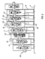
- Bracket 2 are adjustable in the plane of the base plate 1 adjustable.
- Each bracket support 2 carries two clamping elements arranged one above the other, which define an intermediate space between them.
- Each clamping element 33 is slidably fastened by screws 34 in the region of a vertically aligned elongated hole 35 in the mold carrier 3.
- the mold carrier 3 is adjustably fastened to the console carrier 2 in two mutually perpendicular spatial axes.
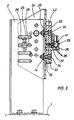
- the tensioning elements each define support surfaces 40 and thus carry a bending template 36 which, in the exemplary embodiment shown (see FIG. 3), consists of two parts.
- the bending template 36 here consists of a vertical template 37 and a horizontal template 38.
- the two templates define a bending profile 39, via which a profile in the exact profile shape of the bending profile 39 is bent by means of bending rollers indicated in FIG.
- the bending template 36 thus defines the position, rotation and inclination of the bending profile 39 to be bent, while the bending profile 39 itself defines the geometric dimensions of the profile to be bent.
- the clamping elements 33 are still not tightly clamped with the bending template 36.
- the bending template 36 can first be freely bent (using tools) so that it corresponds exactly to the required bending line. According to Figure 1, the bending template 36 is only temporarily held on the clamping elements 33.
- the clamping elements are firmly connected to the bending template 36.
- the clamping elements 33 are first rotated around the bearing points in the screws 34, so that the rounded support surfaces 40 wedge with the associated surfaces of the bending template 36. This is because the support surface 30 is eccentric to the bearing point in the screw 34 of the clamping element 33.
- a screw 42 is used to connect the three parts (33 and 36).
- the screw 42 engages through the mutually aligned longitudinal bores 44 in the opposing clamping elements 33 and additionally through a bore 43 in the bending template 36.
- the bores 43, 44 are subsequently produced by simply drilling through the clamping elements aligned in FIG. 2, after which the screw 42 is then passed through and screwed. In this way, a firm and permanent connection of the tensioning elements to the bending template 36 takes place.
- a further screw 41 is screwed into the bending template 36, each of which is connected to a clamping element 33.
- Such screws 41 are arranged, for example, only in every 4th or 5th clamping element 33.
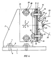
- FIGS. 4 and 5 A further embodiment of a bending tool according to the invention is explained with reference to FIGS. 4 and 5.
- bracket supports 2 are fastened to a base plate 1, with corresponding screws 7 engaging in threaded bores 8 in the base plate 1.
- Elongated holes 9 are provided in the area of the bracket supports, so that the bracket supports 2 are arranged so that they can be moved and locked on the base plate.
- Each bracket support 2 has a front plate 10, in which a plurality of receiving bores 11 are provided.
- the screw bolt 12 of a fastening screw 13 passes through each receiving bore 11, and a nut connection 14 is arranged on the rear of the front plate 10.
- mold carriers 3 which, as stated at the outset, define the bending shape.
- the mold carriers 3 have bores 15 which are penetrated by the threaded bolts 12.
- the threaded bolts carry clamping claws 16 which have fingers 17 pointing towards one another, the fingers 17 engaging in an associated groove 18 of the profiled support 4.
- the profile carrier 4 is displaceable in the Z direction, because the clamping claws 16 have elongated holes 19 aligned in the Z direction.
- the clamping claws 16 can thus be displaced in the area of the elongated holes 19, as a result of which the profile carrier 4 can thus be displaced in the Z axis.
- the profile carrier 4 has an outer profile 20 which engages in the inner profile of the profile 21 to be bent.
- the profile 21 to be bent is thus stabilized during the bending process.
- Profile rollers 22, 23 rest on the outside on the profile 21 to be bent.
- the bracket 2 are formed in two parts and consist of two parts, the front panels 10 are not fixed to the bracket, but, as shown in Figure 2, the front panels via appropriate screw connections 25 with the part 24 of Console bracket are adjustably connected.
- An angular position of the profile carrier 4 in relation to the plane of the base plate can thus be set.
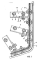
- Figure 3 shows a modified embodiment where it can be seen that a profile cylinder 5 is arranged in the area of the corner, which in turn is adjustable.
- the profile cylinder 5 is arranged on a support plate 27, which is connected to the base plate 1 with corresponding screw connections 28.
- elongated holes are again arranged to ensure the adjustability of the profile cylinder 5 parallel to the plane of the base plate 1.
- a section through the profile cylinder 5 can be seen in FIG. 4.
- the profile cylinder 6 preferably consists of three parts, with a front piece 29, a profile support 30 and a chuck piece 31; all parts are connected to the carrier plate 27 by a clamping screw 32.
- clamping screw 32 extends through an elongated hole 34 in the support plate 27 so that the entire structure, consisting of the parts 29, 30, 31, can also be adjusted parallel to the base plate.
- the further screw 35 serves to fasten the profiled support formed from plastic to the outer circumference of the profiled support 4, while the screw connection 33 serves to fasten the shaped support 3 to the outer circumference of the profiled support.
- the tool can still be arranged adjustably via hydraulic or pneumatic cylinders, ie the geometry in the areas of narrow and wide radii can be changed depending on the batch difference, so that a profile retains its nominal size despite (new) strength.
- a spring-back component is thereby assigned to the tool; the sensitive adjustment takes into account different material properties of different batches.
Landscapes
- Engineering & Computer Science (AREA)
- Mechanical Engineering (AREA)
- Bending Of Plates, Rods, And Pipes (AREA)
- Forklifts And Lifting Vehicles (AREA)
- Hand Tools For Fitting Together And Separating, Or Other Hand Tools (AREA)
- Moulds For Moulding Plastics Or The Like (AREA)
Applications Claiming Priority (2)
| Application Number | Priority Date | Filing Date | Title |
|---|---|---|---|
| DE3915855 | 1989-05-16 | ||
| DE3915855A DE3915855A1 (de) | 1989-05-16 | 1989-05-16 | Universal-biegewerkzeug |
Publications (3)
| Publication Number | Publication Date |
|---|---|
| EP0398280A2 true EP0398280A2 (fr) | 1990-11-22 |
| EP0398280A3 EP0398280A3 (fr) | 1991-07-17 |
| EP0398280B1 EP0398280B1 (fr) | 1994-08-17 |
Family
ID=6380708
Family Applications (1)
| Application Number | Title | Priority Date | Filing Date |
|---|---|---|---|
| EP90109222A Expired - Lifetime EP0398280B1 (fr) | 1989-05-16 | 1990-05-16 | Appareil de pliage universel |
Country Status (4)
| Country | Link |
|---|---|
| US (1) | US5099668A (fr) |
| EP (1) | EP0398280B1 (fr) |
| AT (1) | ATE110015T1 (fr) |
| DE (2) | DE3915855A1 (fr) |
Cited By (2)
| Publication number | Priority date | Publication date | Assignee | Title |
|---|---|---|---|---|
| US5131254A (en) * | 1991-01-29 | 1992-07-21 | Whitefab, Inc | Apparatus for bending beams |
| WO2009083609A3 (fr) * | 2008-01-03 | 2009-09-24 | Edag Gmbh & Co. Kgaa | Procédé de flexion d'une pièce |
Families Citing this family (2)
| Publication number | Priority date | Publication date | Assignee | Title |
|---|---|---|---|---|
| IE960695A1 (en) * | 1996-10-01 | 1998-04-08 | Rainforest R & D Limited | An apparatus and a method for bending a component |
| US8096874B2 (en) | 2007-09-27 | 2012-01-17 | Igt | Gaming system and method having progressive awards with meter increase events |
Family Cites Families (15)
| Publication number | Priority date | Publication date | Assignee | Title |
|---|---|---|---|---|
| US337113A (en) * | 1886-03-02 | The ribs or frames of metallic ships | ||
| US504628A (en) * | 1893-09-05 | Machine for forming sheet metal | ||
| US2347575A (en) * | 1942-04-22 | 1944-04-25 | Harold E Neverdal | Beam bending machine |
| US2533470A (en) * | 1945-03-10 | 1950-12-12 | Socrates H Kapelis | Bending apparatus |
| US2714916A (en) * | 1952-12-03 | 1955-08-09 | Lee B Green | Work gripping and flexing chuck mechanism |
| US3033266A (en) * | 1958-07-11 | 1962-05-08 | Russell E Leckner | Stretch forming machine |
| US3181331A (en) * | 1962-06-27 | 1965-05-04 | Ite Circuit Breaker Ltd | Article bending machine |
| DE1261871B (de) * | 1965-02-05 | 1968-02-29 | Brueninghaus Gmbh Stahlwerke | Einrichtung zum Biegen und Haerten von Blattfedern |
| US3426569A (en) * | 1967-01-31 | 1969-02-11 | Cyril Bath Co | Stretch forming machine and segmental adjustable die combination |
| JPS5220023B2 (fr) * | 1973-06-25 | 1977-06-01 | ||
| US4117707A (en) * | 1977-09-23 | 1978-10-03 | Westinghouse Electric Corp. | Apparatus for shaping electrical coils for dynamoelectric machines |
| US4292834A (en) * | 1980-03-28 | 1981-10-06 | Norwalk Investment Club | Irregular shape rod bending apparatus |
| US4450708A (en) * | 1982-06-21 | 1984-05-29 | King Industrial Products Co., Inc. | Universal, adjustable bending form for shaping electrical windings |
| DE3307283A1 (de) * | 1983-03-02 | 1984-09-06 | W. Eckold AG, Trimmis | Rohrbiegeanlage |
| US4548065A (en) * | 1983-05-27 | 1985-10-22 | Rockwell International Corporation | Stretch-forming tool |
-
1989
- 1989-05-16 DE DE3915855A patent/DE3915855A1/de active Granted
-
1990
- 1990-05-15 US US07/523,435 patent/US5099668A/en not_active Expired - Fee Related
- 1990-05-16 AT AT90109222T patent/ATE110015T1/de not_active IP Right Cessation
- 1990-05-16 DE DE59006814T patent/DE59006814D1/de not_active Expired - Fee Related
- 1990-05-16 EP EP90109222A patent/EP0398280B1/fr not_active Expired - Lifetime
Cited By (4)
| Publication number | Priority date | Publication date | Assignee | Title |
|---|---|---|---|---|
| US5131254A (en) * | 1991-01-29 | 1992-07-21 | Whitefab, Inc | Apparatus for bending beams |
| WO1992012812A1 (fr) * | 1991-01-29 | 1992-08-06 | Whitefab, Inc. | Appareil de cintrage de poutres |
| EP0569536B1 (fr) * | 1991-01-29 | 1998-04-22 | Whitefab, Inc. | Appareil de cintrage de poutres |
| WO2009083609A3 (fr) * | 2008-01-03 | 2009-09-24 | Edag Gmbh & Co. Kgaa | Procédé de flexion d'une pièce |
Also Published As
| Publication number | Publication date |
|---|---|
| DE3915855C2 (fr) | 1992-09-03 |
| EP0398280B1 (fr) | 1994-08-17 |
| DE3915855A1 (de) | 1990-11-22 |
| US5099668A (en) | 1992-03-31 |
| DE59006814D1 (de) | 1994-09-22 |
| ATE110015T1 (de) | 1994-09-15 |
| EP0398280A3 (fr) | 1991-07-17 |
Similar Documents
| Publication | Publication Date | Title |
|---|---|---|
| DE2822826C2 (de) | Werkzeug zum Ausbrechen von in einer Stanzpresse vorgestanzten Nutzen | |
| EP1331059B1 (fr) | Dispositif pour le positionnement de réservoirs et procédés pour la fixation, le positionement et l'usinage de réservoirs, tonneaux, chaudrons, tubes et similaires utilisant un tel dispositif | |
| EP0245635B1 (fr) | Dispositif de fixation pour panneaux | |
| DE9114722U1 (de) | Rahmen zur Halterung von Zuschnitten für den Bezug von Formteilen | |
| DE19516073B4 (de) | Vorrichtung zum Stanzen von Nutzen aus Bögen | |
| EP0330970A2 (fr) | Dispositif pour le positionnement d'éléments de cadre courbes et pour le fraisage de rainures trapézoidales dans ces éléments de cadre | |
| EP0398280A2 (fr) | Appareil de pliage universel | |
| DE19508864C1 (de) | Maschine zum Ummanteln von länglichen Werkstücken | |
| EP0076783B1 (fr) | Machine à cintrer des tubes et des barres profilés | |
| DE3802091C1 (fr) | ||
| EP1103348B1 (fr) | Dispositif de soudage de cadres | |
| DE4223094A1 (de) | Vorrichtung zum Einbringen von paßgenauen Bohrungen in Nummernschilder für Kraftfahrzeuge | |
| DE2613673A1 (de) | Spannvorrichtung | |
| DE2042509A1 (de) | Vorrichtung zur Befestigung von oberen Teilstücken an Aufnahmeschienen | |
| DE2918470C2 (de) | Vorrichtung zum Spannen eines Möbelkorpus und zum Einbringen von Bohrungen für Schraubverbinder | |
| DE2706499A1 (de) | An einem mast anbringbare haltevorrichtung fuer geodaetische instrumente | |
| DE2133594C3 (de) | Vorrichtung zum Reparieren deformierter Gehäuse aus verformbaren Material | |
| DE3525852A1 (de) | Bohrlehre zum herstellen von verbindungsbohrungen zum verbinden eines ersten plattenfoermigen werkstuecks mit einem anderen werkstueck | |
| DE9304524U1 (de) | Werkstückspannvorrichtung | |
| DE1292099B (de) | Schraubstock | |
| DE3511957C2 (fr) | ||
| EP3871761A1 (fr) | Dispositif de mélange doté d'un dispositif de serrage pour un récipient à produit mélangé, en particulier pour un seau de peinture et/ou pour un seau de nettoyage | |
| AT505991A2 (de) | Schablone zum anreissen und übertragen von massen auf und zum einbringen von ausnehmungen in oberflächen von bauteilen | |
| DE2416100A1 (de) | Halteleiste fuer eine druckdecke zur ausfuehrung von farbdruckvorgaengen | |
| CH698237B1 (de) | Schablone zum Anreissen und Übertragen von Massen und zum Positionieren von Werkzeugen auf Oberflächen von Bauteilen. |
Legal Events
| Date | Code | Title | Description |
|---|---|---|---|
| PUAI | Public reference made under article 153(3) epc to a published international application that has entered the european phase |
Free format text: ORIGINAL CODE: 0009012 |
|
| AK | Designated contracting states |
Kind code of ref document: A2 Designated state(s): AT BE CH DE ES FR GB GR IT LI LU NL SE |
|
| PUAL | Search report despatched |
Free format text: ORIGINAL CODE: 0009013 |
|
| AK | Designated contracting states |
Kind code of ref document: A3 Designated state(s): AT BE CH DE ES FR GB GR IT LI LU NL SE |
|
| 17P | Request for examination filed |
Effective date: 19910430 |
|
| 17Q | First examination report despatched |
Effective date: 19920824 |
|
| GRAA | (expected) grant |
Free format text: ORIGINAL CODE: 0009210 |
|
| AK | Designated contracting states |
Kind code of ref document: B1 Designated state(s): AT BE CH DE ES FR GB GR IT LI LU NL SE |
|
| PG25 | Lapsed in a contracting state [announced via postgrant information from national office to epo] |
Ref country code: IT Free format text: LAPSE BECAUSE OF FAILURE TO SUBMIT A TRANSLATION OF THE DESCRIPTION OR TO PAY THE FEE WITHIN THE PRE;WARNING: LAPSES OF ITALIAN PATENTS WITH EFFECTIVE DATE BEFORE 2007 MAY HAVE OCCURRED AT ANY TIME BEFORE 2007. THE CORRECT EFFECTIVE DATE MAY BE DIFFERENT FROM THE ONE RECORDED.SCRIBED TIME-LIMIT Effective date: 19940817 Ref country code: ES Free format text: THE PATENT HAS BEEN ANNULLED BY A DECISION OF A NATIONAL AUTHORITY Effective date: 19940817 Ref country code: FR Effective date: 19940817 Ref country code: GR Free format text: LAPSE BECAUSE OF FAILURE TO SUBMIT A TRANSLATION OF THE DESCRIPTION OR TO PAY THE FEE WITHIN THE PRESCRIBED TIME-LIMIT Effective date: 19940817 Ref country code: NL Effective date: 19940817 Ref country code: BE Effective date: 19940817 Ref country code: GB Effective date: 19940817 |
|
| REF | Corresponds to: |
Ref document number: 110015 Country of ref document: AT Date of ref document: 19940915 Kind code of ref document: T |
|
| REF | Corresponds to: |
Ref document number: 59006814 Country of ref document: DE Date of ref document: 19940922 |
|
| PG25 | Lapsed in a contracting state [announced via postgrant information from national office to epo] |
Ref country code: SE Effective date: 19941117 |
|
| EN | Fr: translation not filed | ||
| NLV1 | Nl: lapsed or annulled due to failure to fulfill the requirements of art. 29p and 29m of the patents act | ||
| GBV | Gb: ep patent (uk) treated as always having been void in accordance with gb section 77(7)/1977 [no translation filed] |
Effective date: 19940817 |
|
| PG25 | Lapsed in a contracting state [announced via postgrant information from national office to epo] |
Ref country code: AT Effective date: 19950516 |
|
| PG25 | Lapsed in a contracting state [announced via postgrant information from national office to epo] |
Ref country code: CH Effective date: 19950531 Ref country code: LU Free format text: LAPSE BECAUSE OF NON-PAYMENT OF DUE FEES Effective date: 19950531 Ref country code: LI Effective date: 19950531 |
|
| PLBE | No opposition filed within time limit |
Free format text: ORIGINAL CODE: 0009261 |
|
| STAA | Information on the status of an ep patent application or granted ep patent |
Free format text: STATUS: NO OPPOSITION FILED WITHIN TIME LIMIT |
|
| 26N | No opposition filed | ||
| REG | Reference to a national code |
Ref country code: CH Ref legal event code: PL |
|
| PG25 | Lapsed in a contracting state [announced via postgrant information from national office to epo] |
Ref country code: DE Effective date: 19960201 |