EP0399090A2 - Corps flottant pour travaux hydrauliques - Google Patents
Corps flottant pour travaux hydrauliques Download PDFInfo
- Publication number
- EP0399090A2 EP0399090A2 EP89114040A EP89114040A EP0399090A2 EP 0399090 A2 EP0399090 A2 EP 0399090A2 EP 89114040 A EP89114040 A EP 89114040A EP 89114040 A EP89114040 A EP 89114040A EP 0399090 A2 EP0399090 A2 EP 0399090A2
- Authority
- EP
- European Patent Office
- Prior art keywords
- stilt
- floating body
- drive
- float
- pontoon
- Prior art date
- Legal status (The legal status is an assumption and is not a legal conclusion. Google has not performed a legal analysis and makes no representation as to the accuracy of the status listed.)
- Granted
Links
Images

Classifications
-
- E—FIXED CONSTRUCTIONS
- E02—HYDRAULIC ENGINEERING; FOUNDATIONS; SOIL SHIFTING
- E02F—DREDGING; SOIL-SHIFTING
- E02F5/00—Dredgers or soil-shifting machines for special purposes
- E02F5/006—Dredgers or soil-shifting machines for special purposes adapted for working ground under water not otherwise provided for
-
- B—PERFORMING OPERATIONS; TRANSPORTING
- B63—SHIPS OR OTHER WATERBORNE VESSELS; RELATED EQUIPMENT
- B63B—SHIPS OR OTHER WATERBORNE VESSELS; EQUIPMENT FOR SHIPPING
- B63B21/00—Tying-up; Shifting, towing, or pushing equipment; Anchoring
- B63B21/50—Anchoring arrangements or methods for special vessels, e.g. for floating drilling platforms or dredgers
-
- B—PERFORMING OPERATIONS; TRANSPORTING
- B63—SHIPS OR OTHER WATERBORNE VESSELS; RELATED EQUIPMENT
- B63H—MARINE PROPULSION OR STEERING
- B63H19/00—Marine propulsion not otherwise provided for
- B63H19/08—Marine propulsion not otherwise provided for by direct engagement with water-bed or ground
-
- E—FIXED CONSTRUCTIONS
- E02—HYDRAULIC ENGINEERING; FOUNDATIONS; SOIL SHIFTING
- E02F—DREDGING; SOIL-SHIFTING
- E02F9/00—Component parts of dredgers or soil-shifting machines, not restricted to one of the kinds covered by groups E02F3/00 - E02F7/00
- E02F9/06—Floating substructures as supports
Definitions
- the invention relates to a floating body for hydraulic engineering work, in particular a pontoon arrangement according to the preamble of claim 1.
- Floating bodies are often used for work under water and on embankments of water bodies, in particular pontoons or pontoon arrangements.
- pontoons On the pontoons, for example, there are excavators, devices for applying sealants, stones, mats or the like to the water floor, etc.
- the pontoons have to be positioned relatively precisely, held in the position occupied and after work has been completed in a new place precisely positioned and anchored again will. It is known to hold pontoons in a predetermined location using piles or stilts. It is also known to fix and move pontoons using ropes. The creation of a berth with the help of piles is disadvantageous because the piles sometimes drill very deep into the water floor.
- the resulting holes must be filled up by appropriate reworking and provided with the same covering as the rest of the water floor. This work can often only be carried out by divers, since the holes cannot be seen from above water. Stopping at the berth with the help of ropes is disadvantageous because the pontoon can hardly be reached in a calm, immobile position. Moving with the help of ropes is extremely complex and cumbersome.
- the invention has for its object to provide a floating body for hydraulic engineering work, in particular a pontoon arrangement, which can be moved and anchored in a simple manner and which keeps the position assumed regardless of water and wind influences in a relatively quiet position.
- the floating body according to the invention also provides a pole or a stilts, but this is provided with a drive.
- the drive is preferably a caterpillar drive.
- Various options are conceivable for the drive. It is particularly advantageous to use a hydraulic motor, which is preferably attached to the stilt near the drive.
- the drive is preferably suspended on a rocker arm, the pivot axis of which is transverse to the direction of advance.
- the drive is preferably also steerable, e.g. by swiveling around a vertical axis or by using two caterpillar tracks side by side.
- the stilt is mounted in a guide of the floating body so as to be adjustable in height.
- the height adjustment not only is it adapted to the different water depths, it also enables the setting of a certain ground pressure with which the undercarriage is supported on the ground. When moving the float, this pressure must be sufficient so that the drive due to the buoyancy of the float body does not lift off the floor.
- the soil pressure is only chosen so high that it does not sink into the body of water and thus does not affect the installed layers.
- the height adjustment of the stilt or the adjustment of the ground pressure is carried out according to a further embodiment of the invention with the aid of at least one hydraulic cylinder which engages the stilt and which is articulated with the other end on the floating body.
- a single drive to be attached to a post may be sufficient for stopping at a berth and moving.
- the arrangement is particularly advantageous Two or more piles with drives, for example on the two sides of a pontoon or in a slot in the pontoon.
- a further embodiment of the invention provides that a further running gear is arranged at a distance from a stilt having a running gear on a cantilever of the floating body supply of the float on a towpath or the like.
- a floating body can be moved precisely along an embankment, for example a canal embankment, so that, for example, a textile mat can be laid with the aid of a laying roller.
- a further embodiment of the invention provides that the stilt is arranged in an end region of the floating body, a carriage is movably mounted laterally or above a slot in the floating body for guiding sheet piles for a sheet pile wall or the like and in the other end region a second, preferably height-adjustable stilt is attached to the floating body, which has a longitudinal guide at the lower end, which cooperates with the top of the finished sheet pile wall.
- the slide which serves as a guide for the sheet piles, is aligned relatively precisely to the sheet pile wall that has already been completed, so that the sheet piles can be easily positioned and rammed.
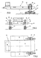
- a pontoon arrangement 10 can be seen in FIGS. 1 to 3, which consists of a central larger pontoon 11 and two laterally attached pontoons 12, 13.
- a control cabin 15 is arranged at the rear end of the pontoon 11.
- Guides 16, 17 for stilts 18, 19 are attached to the front of the side pontoons 12, 13.
- the stilts 18, 19 are guided so that they can move longitudinally or vertically.
- a collar 20 and 21 is connected to the stilts, on which two hydraulic cylinders 22 engage on opposite sides and are articulated on the guide 16 and 17 at the other end.
- the stilts 18, 19 can be adjusted in their height.
- a gas pressure spring is also coupled to the hydraulic cylinders 22 (not shown), as a result of which the adjusting cylinders act like shock absorbers.
- a crawler track 23 or 24 is arranged at the lower end of the stilts 18, 19, a crawler track 23 or 24 is arranged.
- the crawler tracks 23, 24 are driven by a hydraulic motor (not shown) which is arranged on the stilt 18, 19 in the lower region and is supplied by a hydraulic generator on the deck of the pontoon 11.
- the Pontoon assembly 10 are advanced in the desired manner and held at any location.
- a steering option is preferably also provided, for example by using the drive around the axis of the stilts or by using two caterpillar tracks which can be driven independently of one another.
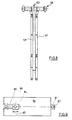
- a pontoon 30 is shown in FIGS. 4 and 5, which supports a laying roller 31 on one longitudinal side.
- the laying roller 31 is pivoted at 32 and held at the other end by ropes 33.
- a boom 34 is arranged on the deck of the pontoon 30, with the aid of which the rope 33 can be secured or caught up in order to set a different angular position of the roller 31 with respect to the horizontal. 5 this is done in order to adapt the angular position of the roller 31 to the angle of an embankment 35.
- a crane 36 which is used to handle the roller 31, for example to wind a mat onto the roller 31, which is then to be applied by the laying roller 31 to the embankment.
- a stilts with undercarriage which arrangement is designated overall by 37. It resembles the stilts 18, 19 with the undercarriage 23, 24 according to FIGS. 1 to 3, so that they will not be dealt with in detail.
- the pontoon 30 has a boom 38 which is only relatively low in height.
- a two-armed rocker 40 is pivotally mounted on the boom 38, which holds a frame 41 of a crawler track 42.
- An adjusting cylinder 43 acts on the rocker 40 in order to adjust the height of the carriage 42.
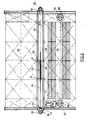
- two elongated pontoons 50, 51 are coupled to one another on the longitudinal sides at a distance.
- a continuous gap is formed between the pontoons 50, 51, in which two rails 52, 53a are attached in parallel.
- a carriage 53 runs on the rails by means of two pairs of rollers 54, 55.
- the carriage is advanced by means of a rope 56 which is wound on a winch 57.
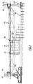
- the car essentially consists Lichen from two parallel spaced stiffened plates 57a, 58, which form between them a guide for sheet piles 59 shown in dashed lines, which are driven from the pontoon arrangement with a ramming device, not shown, to form a sheet pile wall 60 (see Fig. 7).
- the plates 57a, 58 are cut out at the top, so that guidance can be accomplished when the upper end of the sheet piles 59 is under water.
- a guide 61 for a stilt 62 is arranged at the level of the continuous gap.
- the stilt is guided so as to be freely adjustable in height.
- the stilt 62 has a longitudinal guide 63 which engages over the sheet pile wall 60 on both sides on the upper side.
- the stilt 64 At the left end there is another stilt 64 at the level of the gap, which is also freely adjustable in height in a guide 65.
- the stilt 64 At the lower end, the stilt 64 has a caterpillar drive 66 which can be designed in accordance with the caterpillar drives according to FIGS. 1 to 3. If after finishing a sheet pile over a Length of the pontoon arrangement to create additional sheet piling sections, the pontoon arrangement can be advanced by the drive 66 by approximately its own length. However, additional drives can also be provided for this purpose.
- guides 67, 68 in the pontoon 51 are indicated for stilts 69, 70, which can be designed according to the stilts 18, 19 according to Figures 1 to 3 with undercarriages corresponding to the undercarriages 23, 24 of the first embodiment.
- An electric motor 71 is also indicated in FIG. 6, which drives a hydraulic pump 72 for the individual hydraulic motors of the caterpillar drives described.
- the stilts 69, 70 can, however, have no undercarriage or only serve to additionally support the pontoons 50, 51. They can be raised by hydraulic cylinders to enable propulsion.
- Fig. 6 it can be seen that the guide 65 for the stilt 64 is stabilized by a hydraulic cylinder 73.
Landscapes
- Engineering & Computer Science (AREA)
- Mechanical Engineering (AREA)
- Civil Engineering (AREA)
- Combustion & Propulsion (AREA)
- Ocean & Marine Engineering (AREA)
- Mining & Mineral Resources (AREA)
- Chemical & Material Sciences (AREA)
- General Engineering & Computer Science (AREA)
- Structural Engineering (AREA)
- Bridges Or Land Bridges (AREA)
- Placing Or Removing Of Piles Or Sheet Piles, Or Accessories Thereof (AREA)
- Lubricants (AREA)
- Fluid-Pressure Circuits (AREA)
- Cleaning Or Clearing Of The Surface Of Open Water (AREA)
Priority Applications (1)
| Application Number | Priority Date | Filing Date | Title |
|---|---|---|---|
| AT89114040T ATE98312T1 (de) | 1989-05-24 | 1989-07-29 | Schwimmkoerper fuer wasserbauarbeiten. |
Applications Claiming Priority (2)
| Application Number | Priority Date | Filing Date | Title |
|---|---|---|---|
| DE3916857 | 1989-05-24 | ||
| DE3916857A DE3916857A1 (de) | 1989-05-24 | 1989-05-24 | Schwimmkoerper fuer wasserbauarbeiten |
Publications (3)
| Publication Number | Publication Date |
|---|---|
| EP0399090A2 true EP0399090A2 (fr) | 1990-11-28 |
| EP0399090A3 EP0399090A3 (fr) | 1991-11-06 |
| EP0399090B1 EP0399090B1 (fr) | 1993-12-08 |
Family
ID=6381272
Family Applications (1)
| Application Number | Title | Priority Date | Filing Date |
|---|---|---|---|
| EP89114040A Expired - Lifetime EP0399090B1 (fr) | 1989-05-24 | 1989-07-29 | Corps flottant pour travaux hydrauliques |
Country Status (4)
| Country | Link |
|---|---|
| EP (1) | EP0399090B1 (fr) |
| AT (1) | ATE98312T1 (fr) |
| DE (2) | DE3916857A1 (fr) |
| ES (1) | ES2047614T3 (fr) |
Cited By (2)
| Publication number | Priority date | Publication date | Assignee | Title |
|---|---|---|---|---|
| KR100771465B1 (ko) | 2004-01-27 | 2007-10-30 | 한송본 | 대형 테트라포트 축조 방법 |
| CN104002938A (zh) * | 2014-05-28 | 2014-08-27 | 中国石油集团东方地球物理勘探有限责任公司 | 一种组合式超浅水气枪震源系统及工艺方法 |
Families Citing this family (1)
| Publication number | Priority date | Publication date | Assignee | Title |
|---|---|---|---|---|
| DE102006056772A1 (de) * | 2006-12-01 | 2008-06-05 | Joachim Falkenhagen | Verfahren zur Schiffsstabilisierung durch Zugverbindungen zu auf den Grund abgesenkten Gewichten |
Family Cites Families (4)
| Publication number | Priority date | Publication date | Assignee | Title |
|---|---|---|---|---|
| US4493586A (en) * | 1982-02-16 | 1985-01-15 | Morrison-Knudsen Co., Inc. | Rip-rap laying machine and method of laying rip-rap |
| DE3524616A1 (de) * | 1985-07-10 | 1987-01-15 | Messmann Josef Fa | Wasserfahrzeug |
| DE3630273C1 (de) * | 1986-09-05 | 1988-01-28 | Benno Hansen | Buhnensetzvorrichtung |
| DE8811814U1 (de) * | 1988-09-17 | 1988-12-01 | Josef Möbius Bau-Gesellschaft (GmbH + Co), 2000 Hamburg | Vorrichtung zum Verlegen von Bahnmaterial, insbesondere von Filtermatten |
-
1989
- 1989-05-24 DE DE3916857A patent/DE3916857A1/de not_active Withdrawn
- 1989-07-29 AT AT89114040T patent/ATE98312T1/de not_active IP Right Cessation
- 1989-07-29 ES ES89114040T patent/ES2047614T3/es not_active Expired - Lifetime
- 1989-07-29 DE DE89114040T patent/DE58906380D1/de not_active Expired - Fee Related
- 1989-07-29 EP EP89114040A patent/EP0399090B1/fr not_active Expired - Lifetime
Cited By (3)
| Publication number | Priority date | Publication date | Assignee | Title |
|---|---|---|---|---|
| KR100771465B1 (ko) | 2004-01-27 | 2007-10-30 | 한송본 | 대형 테트라포트 축조 방법 |
| CN104002938A (zh) * | 2014-05-28 | 2014-08-27 | 中国石油集团东方地球物理勘探有限责任公司 | 一种组合式超浅水气枪震源系统及工艺方法 |
| CN104002938B (zh) * | 2014-05-28 | 2016-09-07 | 中国石油集团东方地球物理勘探有限责任公司 | 一种组合式超浅水气枪震源系统及工艺方法 |
Also Published As
| Publication number | Publication date |
|---|---|
| DE58906380D1 (de) | 1994-01-20 |
| EP0399090B1 (fr) | 1993-12-08 |
| ES2047614T3 (es) | 1994-03-01 |
| EP0399090A3 (fr) | 1991-11-06 |
| ATE98312T1 (de) | 1993-12-15 |
| DE3916857A1 (de) | 1990-11-29 |
Similar Documents
| Publication | Publication Date | Title |
|---|---|---|
| EP0019909B1 (fr) | Procédé et appareil pour enfouir des câbles et analogues au fond de l'eau | |
| DE3047176A1 (de) | Grabenbagger | |
| DE102007033808A1 (de) | Selbstfahrende Straßenfräsmaschine, insbesondere Großfräse | |
| DE2947466A1 (de) | Grabenbagger | |
| DE2411140A1 (de) | Vorrichtung zum einbetten von auf einem gewaessergrund liegenden rohren | |
| WO1993016945A1 (fr) | Passerelle de liaison mobile a bande transporteuse pour l'exploitation miniere a ciel ouvert | |
| DE69005175T2 (de) | Pfahlrammeinrichtung, Methode zur Beförderung und Errichtung derselben und Methode zur Errichtung von Fundamenten neben Schienen. | |
| DE69011381T2 (de) | Pfahlramme, Verfahren zum Transport und zur Aufstellung einer Pfahlramme und Verfahren zur Herstellung einer Gründung. | |
| DE3141763C2 (de) | Teilschnittschrämmaschine | |
| DE2937205C2 (de) | Kanalbaulängsmaschine | |
| EP0399090A2 (fr) | Corps flottant pour travaux hydrauliques | |
| DE10129825B4 (de) | Herstellung einer Unterwasserwand | |
| DE3524616A1 (de) | Wasserfahrzeug | |
| DE8817049U1 (de) | Vorrichtung zur Herstellung eines Gleisschotterplanums | |
| DE3419205C2 (de) | Gleisbaumaschine zum Verlegen und Ausbauen von montierten Gleisabschnitten oder Gleisverbindungen | |
| DE2623811A1 (de) | Vorrichtung zum verlegen von kabeln o.dgl. im boden | |
| DE2947030C2 (de) | Fahrzeug zum Slippen eines Bootes | |
| DE8907018U1 (de) | Schwimmkörper für Wasserbauarbeiten | |
| DE3635272A1 (de) | Verfahren und anlage zum verlegen von geotextilmatten ueber und unter wasser | |
| DD250729A5 (de) | Einrichtung zum eintreiben von fundamentelementen in erdschichhten | |
| DE3020770C2 (de) | Fahrzeug für den Ausbau von Gruben und Tunnelbauten | |
| DE4018154C2 (de) | Schrämmaschine | |
| DE19524389C1 (de) | Vorrichtung zum Bohren von Löchern und/oder Schlitzen | |
| DE3327061C2 (de) | Anordnung zum kontinuierlichen Verlegen von Kabeln, flexiblen Rohren oder dergleichen im Erdboden | |
| DE3717198A1 (de) | Verlegevorrichtung zum verlegen von geotextilien |
Legal Events
| Date | Code | Title | Description |
|---|---|---|---|
| PUAI | Public reference made under article 153(3) epc to a published international application that has entered the european phase |
Free format text: ORIGINAL CODE: 0009012 |
|
| AK | Designated contracting states |
Kind code of ref document: A2 Designated state(s): AT BE CH DE ES FR GB GR IT LI LU NL SE |
|
| PUAL | Search report despatched |
Free format text: ORIGINAL CODE: 0009013 |
|
| AK | Designated contracting states |
Kind code of ref document: A3 Designated state(s): AT BE CH DE ES FR GB GR IT LI LU NL SE |
|
| 17P | Request for examination filed |
Effective date: 19911114 |
|
| 17Q | First examination report despatched |
Effective date: 19921106 |
|
| GRAA | (expected) grant |
Free format text: ORIGINAL CODE: 0009210 |
|
| AK | Designated contracting states |
Kind code of ref document: B1 Designated state(s): AT BE CH DE ES FR GB GR IT LI LU NL SE |
|
| PG25 | Lapsed in a contracting state [announced via postgrant information from national office to epo] |
Ref country code: GR Free format text: LAPSE BECAUSE OF FAILURE TO SUBMIT A TRANSLATION OF THE DESCRIPTION OR TO PAY THE FEE WITHIN THE PRESCRIBED TIME-LIMIT Effective date: 19931208 |
|
| REF | Corresponds to: |
Ref document number: 98312 Country of ref document: AT Date of ref document: 19931215 Kind code of ref document: T |
|
| REF | Corresponds to: |
Ref document number: 58906380 Country of ref document: DE Date of ref document: 19940120 |
|
| GBT | Gb: translation of ep patent filed (gb section 77(6)(a)/1977) |
Effective date: 19940105 |
|
| REG | Reference to a national code |
Ref country code: ES Ref legal event code: FG2A Ref document number: 2047614 Country of ref document: ES Kind code of ref document: T3 |
|
| ITF | It: translation for a ep patent filed | ||
| ET | Fr: translation filed | ||
| PG25 | Lapsed in a contracting state [announced via postgrant information from national office to epo] |
Ref country code: AT Effective date: 19940729 |
|
| PG25 | Lapsed in a contracting state [announced via postgrant information from national office to epo] |
Ref country code: SE Effective date: 19940730 Ref country code: ES Free format text: LAPSE BECAUSE OF THE APPLICANT RENOUNCES Effective date: 19940730 |
|
| PG25 | Lapsed in a contracting state [announced via postgrant information from national office to epo] |
Ref country code: LU Free format text: LAPSE BECAUSE OF NON-PAYMENT OF DUE FEES Effective date: 19940731 Ref country code: LI Effective date: 19940731 Ref country code: CH Effective date: 19940731 Ref country code: BE Effective date: 19940731 |
|
| PLBE | No opposition filed within time limit |
Free format text: ORIGINAL CODE: 0009261 |
|
| STAA | Information on the status of an ep patent application or granted ep patent |
Free format text: STATUS: NO OPPOSITION FILED WITHIN TIME LIMIT |
|
| 26N | No opposition filed | ||
| BERE | Be: lapsed |
Owner name: JOSEF MOBIUS BAUGESELLSCHAFT (G.M.B.H. & CO.) Effective date: 19940731 |
|
| EUG | Se: european patent has lapsed |
Ref document number: 89114040.2 Effective date: 19950210 |
|
| REG | Reference to a national code |
Ref country code: CH Ref legal event code: PL |
|
| EUG | Se: european patent has lapsed |
Ref document number: 89114040.2 |
|
| PGFP | Annual fee paid to national office [announced via postgrant information from national office to epo] |
Ref country code: FR Payment date: 19970425 Year of fee payment: 9 |
|
| PGFP | Annual fee paid to national office [announced via postgrant information from national office to epo] |
Ref country code: GB Payment date: 19970721 Year of fee payment: 9 |
|
| PGFP | Annual fee paid to national office [announced via postgrant information from national office to epo] |
Ref country code: NL Payment date: 19970730 Year of fee payment: 9 |
|
| PG25 | Lapsed in a contracting state [announced via postgrant information from national office to epo] |
Ref country code: GB Free format text: LAPSE BECAUSE OF NON-PAYMENT OF DUE FEES Effective date: 19980729 |
|
| PGFP | Annual fee paid to national office [announced via postgrant information from national office to epo] |
Ref country code: DE Payment date: 19980922 Year of fee payment: 10 |
|
| PG25 | Lapsed in a contracting state [announced via postgrant information from national office to epo] |
Ref country code: NL Free format text: LAPSE BECAUSE OF NON-PAYMENT OF DUE FEES Effective date: 19990201 |
|
| GBPC | Gb: european patent ceased through non-payment of renewal fee |
Effective date: 19980729 |
|
| PG25 | Lapsed in a contracting state [announced via postgrant information from national office to epo] |
Ref country code: FR Free format text: LAPSE BECAUSE OF NON-PAYMENT OF DUE FEES Effective date: 19990331 |
|
| NLV4 | Nl: lapsed or anulled due to non-payment of the annual fee |
Effective date: 19990201 |
|
| REG | Reference to a national code |
Ref country code: FR Ref legal event code: ST |
|
| REG | Reference to a national code |
Ref country code: ES Ref legal event code: FD2A Effective date: 19991007 |
|
| PG25 | Lapsed in a contracting state [announced via postgrant information from national office to epo] |
Ref country code: DE Free format text: LAPSE BECAUSE OF NON-PAYMENT OF DUE FEES Effective date: 20000503 |
|
| PG25 | Lapsed in a contracting state [announced via postgrant information from national office to epo] |
Ref country code: IT Free format text: LAPSE BECAUSE OF NON-PAYMENT OF DUE FEES;WARNING: LAPSES OF ITALIAN PATENTS WITH EFFECTIVE DATE BEFORE 2007 MAY HAVE OCCURRED AT ANY TIME BEFORE 2007. THE CORRECT EFFECTIVE DATE MAY BE DIFFERENT FROM THE ONE RECORDED. Effective date: 20050729 |