EP0399093A2 - Kocheinrichtung - Google Patents
Kocheinrichtung Download PDFInfo
- Publication number
- EP0399093A2 EP0399093A2 EP89117699A EP89117699A EP0399093A2 EP 0399093 A2 EP0399093 A2 EP 0399093A2 EP 89117699 A EP89117699 A EP 89117699A EP 89117699 A EP89117699 A EP 89117699A EP 0399093 A2 EP0399093 A2 EP 0399093A2
- Authority
- EP
- European Patent Office
- Prior art keywords
- cooking
- utensil
- heating
- stirring
- foil
- Prior art date
- Legal status (The legal status is an assumption and is not a legal conclusion. Google has not performed a legal analysis and makes no representation as to the accuracy of the status listed.)
- Withdrawn
Links
Images











Classifications
-
- H—ELECTRICITY
- H05—ELECTRIC TECHNIQUES NOT OTHERWISE PROVIDED FOR
- H05B—ELECTRIC HEATING; ELECTRIC LIGHT SOURCES NOT OTHERWISE PROVIDED FOR; CIRCUIT ARRANGEMENTS FOR ELECTRIC LIGHT SOURCES, IN GENERAL
- H05B6/00—Heating by electric, magnetic or electromagnetic fields
- H05B6/02—Induction heating
- H05B6/06—Control, e.g. of temperature, of power
- H05B6/062—Control, e.g. of temperature, of power for cooking plates or the like
-
- A—HUMAN NECESSITIES
- A47—FURNITURE; DOMESTIC ARTICLES OR APPLIANCES; COFFEE MILLS; SPICE MILLS; SUCTION CLEANERS IN GENERAL
- A47J—KITCHEN EQUIPMENT; COFFEE MILLS; SPICE MILLS; APPARATUS FOR MAKING BEVERAGES
- A47J27/00—Cooking-vessels
- A47J27/004—Cooking-vessels with integral electrical heating means
-
- A—HUMAN NECESSITIES
- A47—FURNITURE; DOMESTIC ARTICLES OR APPLIANCES; COFFEE MILLS; SPICE MILLS; SUCTION CLEANERS IN GENERAL
- A47J—KITCHEN EQUIPMENT; COFFEE MILLS; SPICE MILLS; APPARATUS FOR MAKING BEVERAGES
- A47J27/00—Cooking-vessels
- A47J27/14—Cooking-vessels for use in hotels, restaurants, or canteens
-
- H—ELECTRICITY
- H05—ELECTRIC TECHNIQUES NOT OTHERWISE PROVIDED FOR
- H05B—ELECTRIC HEATING; ELECTRIC LIGHT SOURCES NOT OTHERWISE PROVIDED FOR; CIRCUIT ARRANGEMENTS FOR ELECTRIC LIGHT SOURCES, IN GENERAL
- H05B6/00—Heating by electric, magnetic or electromagnetic fields
- H05B6/02—Induction heating
- H05B6/10—Induction heating apparatus, other than furnaces, for specific applications
- H05B6/12—Cooking devices
- H05B6/1209—Cooking devices induction cooking plates or the like and devices to be used in combination with them
- H05B6/1227—Cooking devices induction cooking plates or the like and devices to be used in combination with them for wok pans and wok pans supports for induction cooking plates
-
- H—ELECTRICITY
- H05—ELECTRIC TECHNIQUES NOT OTHERWISE PROVIDED FOR
- H05B—ELECTRIC HEATING; ELECTRIC LIGHT SOURCES NOT OTHERWISE PROVIDED FOR; CIRCUIT ARRANGEMENTS FOR ELECTRIC LIGHT SOURCES, IN GENERAL
- H05B6/00—Heating by electric, magnetic or electromagnetic fields
- H05B6/02—Induction heating
- H05B6/10—Induction heating apparatus, other than furnaces, for specific applications
- H05B6/12—Cooking devices
- H05B6/1209—Cooking devices induction cooking plates or the like and devices to be used in combination with them
- H05B6/1236—Cooking devices induction cooking plates or the like and devices to be used in combination with them adapted to induce current in a coil to supply power to a device and electrical heating devices powered in this way
-
- Y—GENERAL TAGGING OF NEW TECHNOLOGICAL DEVELOPMENTS; GENERAL TAGGING OF CROSS-SECTIONAL TECHNOLOGIES SPANNING OVER SEVERAL SECTIONS OF THE IPC; TECHNICAL SUBJECTS COVERED BY FORMER USPC CROSS-REFERENCE ART COLLECTIONS [XRACs] AND DIGESTS
- Y02—TECHNOLOGIES OR APPLICATIONS FOR MITIGATION OR ADAPTATION AGAINST CLIMATE CHANGE
- Y02B—CLIMATE CHANGE MITIGATION TECHNOLOGIES RELATED TO BUILDINGS, e.g. HOUSING, HOUSE APPLIANCES OR RELATED END-USER APPLICATIONS
- Y02B40/00—Technologies aiming at improving the efficiency of home appliances, e.g. induction cooking or efficient technologies for refrigerators, freezers or dish washers
-
- Y—GENERAL TAGGING OF NEW TECHNOLOGICAL DEVELOPMENTS; GENERAL TAGGING OF CROSS-SECTIONAL TECHNOLOGIES SPANNING OVER SEVERAL SECTIONS OF THE IPC; TECHNICAL SUBJECTS COVERED BY FORMER USPC CROSS-REFERENCE ART COLLECTIONS [XRACs] AND DIGESTS
- Y10—TECHNICAL SUBJECTS COVERED BY FORMER USPC
- Y10S—TECHNICAL SUBJECTS COVERED BY FORMER USPC CROSS-REFERENCE ART COLLECTIONS [XRACs] AND DIGESTS
- Y10S99/00—Foods and beverages: apparatus
- Y10S99/14—Induction heating
Definitions
- the present invention relates to domestic food cooking apparatus and systems generally.
- U.S. Patent 3,635,147 describes a combination cooking-stirring vessel in which two sets of blades are rotated continuously by apparatus of a motor drive applied to the rim of a generally round bowl, as food is heated. One set of blades rotates along the bottom of the bowl except at the center bottom region.
- U.S. Patent 1,790,115 describes apparatus for treating food products comprising a plurality of rotating blades and a curved bottom surface.
- U.S. Patent 4,693,610 describes an electrical household appliance for culinary purposes including apparatus for stirring and heating the contents of a bowl. This apparatus provides continuous rotation of a stirrer adjacent the bottom of a flat bottomed bowl.
- U.S. Patent 4,649,810 describes a microcomputer-controlled, integrated cooking apparatus for automatically preparing culinary dishes.
- the apparatus includes a memory for storing one or more recipe programs.
- the recipe program specifies schedules for dispensing the ingredients from a compartmentalized carousel into a flat bottomed cooking vessel, for heating the vessel and for continuously stirring the contents of the vessel.
- U.S. Patent 1,491,991 describes a beverage mixer and heater which provides stirring of the contents of a container having an electric heating element incorporated in its construction.
- U.S. Patent 4,073,225 describes on an industrial scale, continuously operable meatball cooker employing a trough which is engaged by helical vanes.
- U.S. Patent 3,407,872 employs a trough-like tank having a reciprocating paddle for circulating a heating or cooling fluid.
- U.S. Patent 4,629,843 describes induction cooking apparatus having a ferrite coil support and includes monitoring and control apparatus for preventing heating of the ferrite coil support above its Curie temperature.
- U.S. Patent 4,467,162 describes an arrangement for an induction heating process employing a shielding plate member of non-magnetizable metallic material disposed in a space between a heating coil and a bottom plate.
- U.S. Patent 3,761,668 describes a cooking system wherein small electrical appliances are powered by an induction cooking device.
- U.S. Patent 4,817,510 illustrates cooking apparatus wherein the temperature of cooked food is automatically controlled and varied during a cooking cycle.
- the present invention seeks to provide improved domestic food cooking apparatus as well as integrated, modular versatile domestic cooking systems for quick cooking of most foods in the kitchen.
- cooking will be used throughout to refer generally to the application of heat to foodstuffs in a domestic context and includes, inter alia, heating liquids of various viscosities, and dry roasting of bulk foodstuffs, such as nuts, beans and seeds.
- the cooking center of the present invention may comprise a compact unit which can operate interchangeably with a wide variety of cooking utensils.
- the cooking center is characterized in that it provides fast and uniform cooking at high energy efficiency.
- the cooking center of the present invention is easy to operate and may provide controlled cooking and even stirring of foods.
- a domestic cooking system including at least one cooking utensil defining a food heating surface and including heating apparatus operative to heat the food heating surface by thermal conduction, and a base defining one or more cooking locations arranged for removable engagement with at least one cooking utensil and including apparatus for providing energy to the heating apparatus including an electrical connector disposed at at least one of the cooking locations and configured for mating engagement with at least one of the utensils.
- the cooking system also includes control apparatus disposed in the base for providing automatic timing and temperature control of the operation of the heating apparatus.
- the heating apparatus comprises a foil having at least one layer of an electrical insulative material disposed in intimate touching relationship between the foil and the food heating surface, whereby heat from the heating apparatus is transferred to the food heating surface principally by thermal conduction through the electrical insulative material.
- the layer of electrical insulative material may be applied as a coating to the foil, or alternatively may be a separate element.
- a domestic cooking system comprising a base defining at least one cooking location and comprising electromagnetic induction apparatus including an induction producing element operative to generate electromagnetic flux and at least one high permeability foil disposed so as to direct electromagnetic flux generated by the induction producing element to the cooking location.
- the domestic cooking system also includes at least one cooking utensil defining a food heating surface heated by the electromagnetic flux at the cooking location.
- the utensil is formed, at least partially, of an electrically conductive material.
- the base includes at each cooking location apparatus for sensing the temperature of a cooking utensil in operative engagement therewith.
- the at least one foil is disposed on the opposite side of the induction producing element from the utensil.
- the foil has a Curie temperature exceeding 250 degrees C, and preferably exceeding 320 degrees C.
- each foil has a thickness of less than 0.5 mm, preferably less than 0.05 mm.
- the foil is formed of an amorphous metal alloy.
- the induction producing element is non planar.
- the induction producing element comprises a plurality of induction coils.
- the domestic food preparation apparatus includes apparatus for obtaining temperature information relating to a utensil from the electrical resistance of the heating apparatus.
- the utensil includes temperature monitoring apparatus.
- the domestic food preparation apparatus also includes apparatus for controlling the supply of heat to the heating surface in accordance with the temperature of the utensil.
- the apparatus for controlling the supply of heat comprised apparatus for supplying heat until the temperature of the utensil exceeds the indicated desired temperature by a first threshold and thereafter supplying heat to maintain the difference between the temperature of the utensil and the indicated desired temperature within a second threshold.
- the apparatus for controlling also comprises timing apparatus.
- the domestic food preparation apparatus also includes automatically operative stirring apparatus.
- the stirring apparatus comprises stirring drive apparatus and a stirrer, the stirring drive apparatus including quick coupling apparatus for automatically coupling the stirring drive apparatus to the stirrer.
- the stirring apparatus comprises reciprocal stirring apparatus.
- the utensil comprises a curved bottom surface having a generally circular configuration.
- the stirring apparatus is arranged to undergo pivotal reciprocal motion about a pivot axis located generally at the center of a circle defined by the bottom heating surface for reciprocal motion along the bottom heating surface.
- the stirring apparatus includes a stirring element having at least two generally planar surfaces which lie in planes which are angled with respect to each other and with respect to the bottom heating surface.
- the domestic food preparation apparatus also includes heat reflector apparatus operatively associated with the cooking utensil.
- the domestic food preparation apparatus also includes an inner food holding element associated with the utensil for supporting food.
- heating apparatus comprising induction producing means operative to generate electromagnetic flux and at least one high permeability foil disposed so as to direct electromagnetic flux generated by the induction producing means to a desired heating location.
- the high permeability foil is formed of amorphous metal.
- the induction producing means is non-planar.
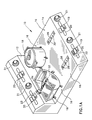
- Figs. 1A and 1B illustrate a cooking system constructed and operative in accordance with a preferred embodiment of the present invention and comprising a cooking center 10, including a back portion 12 and a base portion 14, defining a plurality of cooking locations 16, each arranged for operative association with a cooking utensil 18.
- the upward facing surface of base portion 14 at each of the cooking locations 16 is a heat reflecting surface, which is operative to reflect heat towards the utensil 18.
- the back portion 12 and the base portion 14 comprise various controls for each of the cooking locations 16, such as on-off, temperature and timing controls which may be embodied, for example, in a switch 19 with associated indicator light, a keyboard 20 and a dial 21.
- a status display 22, such as an LCD display may also be provided.
- a status display 22, such as an LCD display may also be provided.
- a coupler 23 of a stirrer drive assembly which is not seen in Figs. 1A - 1B, insofar as it is located at the interior of back portion 12.
- the base portion 14 typically defines a plurality of cooking locations, typically four in number as illustrated. Each cooking location is typically provided with an electrical connector 26 which is arranged for operative engagement with a cooking utensil such as cooking utensils 18 illustrated in Figs. 1A - 1B.
- each of the electrical connectors 26 includes apparatus 28 for supplying electrical power to the cooking utensil 18, typically in the form of a three conductor grounded electrical connection and also includes a data link 30 typically defining a pair of electrical connectors which may provide temperature information from a temperature sensor, integrated into the utensil 18, to utilization and control apparatus in the cooking center 10.
- the cooking center 10 may receive temperature information with respect to a given utensil 18 by other apparatus.
- Fig. 2 illustrates a typical cooking utensil constructed and operative in accordance with a preferred embodiment of the present invention.
- the utensil is configured to have a curved bottom surface 32 (not shown in drawing) of generally uniform width.
- the curvature of bottom surface 32 is generally circular and the surface is arranged to lie about an axis which is collinear with or adjacent to and slightly below the axis of rotation 33 of a stirrer 34 which may be associated with the utensil as seen in Figs. 1A and 1B.
- a cover may be provided for utensil 18.
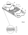
- Electrical heating apparatus preferably such as that shown in Fig. 3, preferably is located within a sealed double walled portion 36 of utensil 18 and is arranged to provide relatively quick and energy efficient, generally uniform heating of a heating surface 35 of the utensil, which is generally coextensive with the extent of the electrical heating apparatus.
- the heating element assembly comprises a heating element 81 preferably in the form of a relatively thin foil of a metal, of typical thickness 0.05 mm, which is configured to define an elongate electrical resistance heating element.
- element 81 has a high ratio of surface coverage, typically in excess of 30% and preferably in excess of 80%, so as to provide very homogeneous heating of heating surface 35 which it heats principally by thermal conduction.
- Element 81 is also selectably configurable and is preferably configured so as to conform to the curvature of heating surface 35 in order to provide homogeneous efficient heating thereof.
- the heating element 81 is located in touching engagement on both sides thereof with a layer of a dielectric material 83, such as a mica, plastic, ceramic or Fiberglas sheet.
- a dielectric material 83 such as a mica, plastic, ceramic or Fiberglas sheet.
- other suitable dielectric materials may be used.
- adhesive or non solid electrical insulation materials, such as plastic materials may be employed.
- metal plates 85 Disposed on the outside surfaces of dielectric layers 83 are metal plates 85, typically formed of stainless steel of thickness 0.6 mm. One of metal plates 85 may serve as the heating surface 35, as illustrated in Fig. 2.
- the electrical insulation layer separating the heating element 81 from the heating surface 35 is a good electrical insulator but also a good thermal conductor, which is operative to transfer heat from the heating element 81 to the heating surface 35.
- a temperature sensor 87 such as a thermistor, is integrally formed with the utensil 18 and is coupled to data link 30 (Figs. 1A and 1B) in order to provide temperature information to the cooking center 10 to enable controlled cooking to take place.
- the utensil 18 is engaged with the base portion 14 of the cooking center 10 from above by a vertical movement.
- the precise positioning of utensil 18 with respect to base portion 14 at a given cooking location may be provided by any suitable apparatus, such as the interconnection between one of electrical connectors 26 (Fig. 1) and a corresponding connector 40 (Figs. 4A-4E) typically associated with the underside of each utensil 18.
- support legs 38 which are attached to each utensil and provide upright support thereof at the cooking location or on any other flat surface.
- the stirrer 34 may be of any suitable configuration so long as it is arranged to travel generally along the curvature of the bottom surface 32 of the utensil, in spaced or touching relationship therewith.
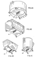
- Figs. 4A - 4E illustrate various types of utensils 18.
- Fig. 4A illustrates a generally cylindrical pot
- Figs 4B illustrates a container of the general type shown in Fig. 2 which is adapted for attachment thereto of automatic stirring apparatus.
- Fig. 4C illustrates a shallow pan suitable for frying
- Fig. 4D illustrates an oven suitable for roasting or baking.
- Fig. 4E illustrates a water heater or coffee maker.
- Each of the above illustrated utensils is preferably formed with a connector 40 which is configured for quick connection with connector 26 for communication of power and temperature information between the cooking center or the base and the utensil.
- the term "utensil" is used herein in an unusually broad sense to include any domestic cooking or heating implement.
- Connector 40 typically includes three pins 41, 43 and 45, which provide an electrical power connection and two additional pins 47 and 49, which provide an electrical signal connection, such as from a temperature sensor, to utilization apparatus.
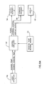
- Fig. 5A illustrates cooking control apparatus particularly useful in the present invention and including user interface apparatus 50, typically incorporating switch 19, keyboard 20 and dial 21 (Fig. 1A), which provide control inputs relating to desired cooking time and desired temperature to control circuitry 52.
- Control circuitry 52 also receives a temperature input from temperature sensing apparatus 54 and provides a power output to a heating assembly 56, such as heating element 81, a stirring control output to a stirring assembly 58, such as stirring assembly 91, described hereinbelow, and a display output to a display 60, such as display 22.
- a heating assembly 56 such as heating element 81
- stirring assembly 58 such as stirring assembly 91
- a display output such as display 22.
- heating assembly 56 may be suitably modified.
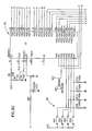
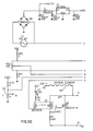
- Figs. 5B, 5C and 5D are electrical schematic illustrations of a portion of the control circuitry of Fig. 5A which is common to three different embodiments which will now be described.
- Fig. 5E is an electrical schematic illustration of control circuitry, which, when combined with the circuitry of Figs. 5B, 5C and 5D is particularly suitable for use with the apparatus of Figs. 1A and 1B, wherein a temperature sensor, such as a thermistor is employed.
- the thermistor or other temperature sensor is preferably integrally formed in the utensil, as illustrated in Fig. 3, but may alternatively be external thereof.
- Fig. 5F is an electrical schematic illustration of control circuitry, which, when combined with the circuitry of Figs. 5B, 5C and 5D is particularly suitable for use with the apparatus of Figs. 14 and 15A - 15C.
- the illustrated heating element is an induction generator 400 of the type illustrated, for example in Fig. 15A.
- the induction generator 400 is powered by switching power and control circuitry which provides a train of AC pulses having a frequency of about 20,000 Hz.
- Fig. 5G is an electrical schematic illustration of control circuitry which, when combined with the circuitry of Figs. 5B, 5C and 5D, is particularly suitable for an embodiment of the invention wherein the temperature of the utensil is determined without the use of a dedicated temperature sensor, but instead by sensing the resistance of the heating element. Circuitry for this purpose is illustrated at reference number 62.
- Fig. 6 is a generalized flow chart illustrating the operation of the circuitry of Figs. 5A - 5G.
- the system upon turning on the system for a cooking location by operating switch 19, following system initialization and fault checks, the system checks the desired temperature indicated by dial 21 and compares it with the temperature indicated by the temperature sensing apparatus. The heating element is operated as appropriate.
- the system operates to monitor the remaining desired cooking time and the ON status of switch 19. It provides for operation of the stirring device throughout cooking or as desired by the user. Upon termination of the desired cooking time, the heating element is turned off and the stirring is typically continued for a given period and then terminated. Visual and/or auditory notification of completed cooking may be provided to the user.
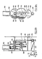
- the stirring assembly 91 preferably comprises a stirring member 93, typically having a configuration as illustrated which defines a pair of stirring surfaces 95, each of which are oriented at an angle alpha greater than 90 degrees with respect to the facing food heating surface 97 of the utensil 18.
- the stirring member 93 is arranged to ride along the food heating surface 97 and is spring mounted on a pair of shafts 99, associated with springs 100, arranged for spring loaded movement parallel to the axes thereof as indicated by arrows 101 to permit the stirring member 93 to follow a food heating surface which may not be at a fixed distance from the axis of rotation of the stirring member 93.
- Shafts 99 are mounted on a transverse mounting assembly 103, which includes two engagement members 105, each of which is formed at its outermost axial facing end 106 with a protrusion 108, which is arranged to removably seat in a corresponding recess 109 formed in a side wall 110 of utensil 18.
- Engagement members 105 are resiliently mounted on a pair of shafts 112 associated with respective springs 113, to permit the engagement members 105 to be moved axially towards each other for engagement with and disengagement from the utensil 18, as illustrated in Fig. 98 and to return to an axially more separated orientation, as illustrated in Fig. 9A, for seating in respective recesses 109.
- the permitted movements of engagement members 105 are illustrated by arrows 114.
- Rotatably mounted on transverse mounting assembly 103 is a rotation axle 115 onto which are mounted shafts 99.
- Fixedly mounted onto rotation axle 115 or formed as an extension thereof is a driving lever 117, which is arranged for driven engagement with a coupler 119, having a coupler engagement portion 120, mounted on a resilient mounting arm 121 (Fig. 7)
- the engagement portion generally comprises a bifurcated cone 122 whose center is slotted by a slot 124 having inclined side walls 126.
- FIG. 11A illustrates steps in the engagement of stirring driving lever 117 with engagement portion 120.
- the driving lever 117 is shown alongside the engagement portion 120.
- the driving lever 117 is shown at the top of engagement portion 120, adjacent slot 124, as mounting arm 121 is bent correspondingly.
- Fig. 11C illustrates seating of the driving lever 117 in slot 124, such that rotation of the coupler 119 about its rotation axis 130, produces rotation of the stirring assembly, and specifically axle 115 about rotation axis 130.
- Figs. 12A and 12B illustrate apparatus for driving the stirring coupler 119 in reciprocal rotational motion.
- the drive apparatus of Figs. 12A and 12B comprises a motor 300 coupled to a conical gear 302, which drives a conical reducing gear 304 to which is fixed an intermediate gear 306, which drives a further reducing gear 308.
- Reducing gear 308 is fixed to an intermediate gear 309, which drives an additional reducing gear 311.
- Gear 311 is fixed to an intermediate gear 313 which drives a further reducing gear 315.
- gear 315 Formed on gear 315 is a pin 310 which engages a cam slot 312 in a cam 314 which is arranged to pivot about an axis 316 and is formed with a toothed gear surface 318.
- Surface 318 which is rotated about axis 316 in reciprocal motion by the engagement of pin 310 in slot 312, drives a gear 320 which drives coupler 119 via a bearing assembly 322, a drive shaft 80 and a mounting element 84.
- Figs. 13A - 13D illustrate stand alone cooking utensils constructed and operative in accordance with a preferred embodiment of the invention.
- Fig. 13A illustrates a shallow pan
- Fig. 13B illustrates a kettle
- Fig. 13C illustrates a flat bottomed cooking pot
- Fig. 13D illustrates a cooking utensil of the general type illustrated in Fig. 2.
- Each of the embodiments of Figs. 13A - 13D is characterized in that it comprises an integrally formed heating assembly which heats a cooking surface principally by thermal conduction, thus providing fast and energy efficient heating.
- the heating assembly in each of the embodiments preferably comprises a heating element of the general type illustrated in Fig. 3 and described hereinabove in connection therewith.
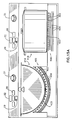
- FIG. 14 illustrates a domestic cooking system constructed and operative in accordance with a preferred embodiment of the present invention.
- the system of Fig. 14 may be generally the same as that shown in Figs. 1A and 1B and described hereinabove in connection therewith with the exception that induction heating apparatus is provided at one or more of the cooking locations.
- FIG. 14 for the sake of illustration, all of the cooking locations are provided with induction heating apparatus.
- a typical induction heating unit is described, for example at page 184 of TDK Product Selection Guide 87/88 catalog no.: AVE002G and in U.S. Patents 4,629,843 and 4,467,162, the description of which is hereby incorporated by reference.
- Figs. 15A, 15B and 15C illustrate three alternative embodiments of the invention employing induction heating.
- Fig. 15A which represents a section taken along the lines XV - XV in Fig. 14, cooking utensils formed of electrically conductive material, such as iron, stainless steel or aluminum may be employed.
- the induction heating apparatus comprises an induction generator assembly 400 including an induction generator 402, comprising an electrical conductor which carries a current flow and is typically, but not necessarily, in the form of one or more coils.
- induction generator 402 Associated with induction generator 402 in electrically insulated relationship therewith, is ferromagnetic material, preferably in the form of a plurality of mutually electrically insulated foils 404 of a high permeability material, preferably an amorphous metal, typically each of thickness 0.025 mm.
- Some preferred materials are ULTRAPERM 10, PERMENORM (5000 H2 and 5000Z) and VITROVAC 4040, all of which are commercially available from VACUUMSCHMELZE of Human, West Germany. Electrical insulation is preferably provided between induction generator 402 and any surface normally engageable by a user.
- a cooking utensil 418 may be provided of any suitable electrically conductive material which is inductively heated by induction generator 402.
- the inductively heated cooking utensil need not necessarily have a flat bottom surface or flat food cooking surface and that the induction generator 402 need not be planar.
- cooking utensils such as a utensil 419, having a curved bottom surface 423 may be heated by induction.
- the induction generator 402 and preferably the entire induction generator assembly 400 is preferably curved to conform to the curvature of the bottom surface 423.
- the magnetic flux produced by induction generator 402 in response to passage of suitable current therethrough is spatially defined by the utensil 419 and by foils 404.
- the use of mutually electrically insulated thin foils 404 instead of a continuous body of ferromagnetic material lowers the heating of the generator assembly 400 as compared with the heating which would occur in a continuous body of ferromagnetic material, such as ferrite.
- foils 404 are formed of a material, such as amorphous metal, which has a relatively high Curie temperature and high permeability, especially at the operating frequency of induction generator assembly 400, typically 20,000 Hz.
- Ferrite slabs employed in the prior art, have a Curie temperature of about 180 degrees C, which requires that care be taken that the induction generator 402 and/or the cooking utensil does not heat the ferrite to above the Curie temperature. Accordingly, in the prior art a relatively thick conductor needs to be used in the induction generator 402 and complicated and expensive protective devices are required in order to ensure that the Ferrite is not overheated.
- foils 404 display high permeability, at the working induction and frequency, preferably in the range of 15000 as compared with a permeability of about 1000 characteristic of Ferrite. This produces extremely efficient induction heating and less radiation leakage than in the prior art.
- the cooking utensil 418 may be provided of any suitable material and includes a heating element 420 fixedly associated therewith which is inductively heated by induction generator 402.
- the heating element 420 comprises a member formed of electrically conductive material, such as stainless steel, having a typical thickness of 0.5 mm.
- the heating element 420 is typically disposed at the bottom of the cooking utensil and may be fixedly attached thereto as by welding or the use of an adhesive, or alternatively integrally formed therewith.
- the utensil 418 includes a covering portion 422 over the heating element 420.
- the covering portion 422 may be made of any suitable material, such as plastic. If the heating element 420 is formed of stainless steel, than the covering portion 422 may be eliminated.
- Fig. 15C shows two alternative arrangements of heating elements 420 and utensils 418.
- the heating element 420 is preferably a body of electrically conductive material which is not attached to the utensil 418.
- the heating element In the arrangement on the left side of the drawing, the heating element is simply placed inside a non-conductive cooking utensil, while in the arrangement on the right side of the drawing, the heating element is placed on the base at a cooking location and any suitable non-conductive cooking utensil is placed thereover.
- ordinary cooking utensils may be employed in the cooking system of the present invention without requiring any modification, provided that suitable heating elements are associated therewith, for example as illustrated.
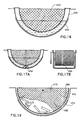
- FIG. 16 illustrates a utensil 450 having associated therewith an apertured inner member 452 adapted for holding food products during deep frying.
- Inner member 452 typically comprises a grid or screen of the type conventionally used in deep frying applications.
- a heating element 454 is fixedly associated with the container 450.
- the utensil 450 may be heated by induction and the heating element 454 may be eliminated.
- Figs. 17A and 17B illustrate an arrangement of the type shown in Fig. 16 with the addition of a stirrer assembly 456.
- the stirrer assembly typically comprises an assembly of the type illustrated in Figs. 7 - 12B.
- FIGs. 18A - 18D illustrate a synergistic integration of the embodiment of Figs. 17A and 17B, wherein an apertured inner member 470 also itself defines a stirrer and is provided with a stirrer mounting and drive arrangement such as that shown in Figs. 7 - 12B, typically including assembly 103, 115 and 117.
- Figs. 18C and 18D illustrate two typical extreme rotated orientations of the apertured inner member 470 with respect to container 450, which is fixedly associated with heating element 454.
- Fig. 19 illustrates a variation of the embodiment of Figs. 18A - 18D in which upstanding bulkhead elements 480 are formed on the interior of inner member 470 to limit sliding of the food products relative thereto.
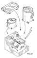
- Fig. 20 illustrates graphically the interchangeability of a plurality of different types of cooking utensils with a single base, which may be flat, as illustrated, or curved.
- Fig. 20 serves to illustrate the use of both inductive and non-inductive heating.
Landscapes
- Physics & Mathematics (AREA)
- Electromagnetism (AREA)
- Engineering & Computer Science (AREA)
- Food Science & Technology (AREA)
- Cookers (AREA)
- Electric Stoves And Ranges (AREA)
- Induction Heating Cooking Devices (AREA)
Applications Claiming Priority (2)
| Application Number | Priority Date | Filing Date | Title |
|---|---|---|---|
| IL90382 | 1989-05-23 | ||
| IL90382A IL90382A (en) | 1989-05-23 | 1989-05-23 | Cooking system |
Publications (2)
| Publication Number | Publication Date |
|---|---|
| EP0399093A2 true EP0399093A2 (de) | 1990-11-28 |
| EP0399093A3 EP0399093A3 (de) | 1992-04-22 |
Family
ID=11059993
Family Applications (1)
| Application Number | Title | Priority Date | Filing Date |
|---|---|---|---|
| EP19890117699 Withdrawn EP0399093A3 (de) | 1989-05-23 | 1989-09-25 | Kocheinrichtung |
Country Status (12)
| Country | Link |
|---|---|
| US (1) | US5070222A (de) |
| EP (1) | EP0399093A3 (de) |
| JP (1) | JPH02309132A (de) |
| AU (1) | AU618401B2 (de) |
| BR (1) | BR8905505A (de) |
| DK (1) | DK532889A (de) |
| GB (1) | GB2232064A (de) |
| IL (1) | IL90382A (de) |
| NO (1) | NO893681L (de) |
| NZ (1) | NZ231167A (de) |
| PT (1) | PT92090A (de) |
| ZA (1) | ZA896793B (de) |
Cited By (2)
| Publication number | Priority date | Publication date | Assignee | Title |
|---|---|---|---|---|
| ES2100802A1 (es) * | 1992-04-10 | 1997-06-16 | Balay Sa | Dispositivo para calentamiento por induccion. |
| CN108348088A (zh) * | 2015-11-09 | 2018-07-31 | 三星电子株式会社 | 烹饪装置及其控制方法 |
Families Citing this family (25)
| Publication number | Priority date | Publication date | Assignee | Title |
|---|---|---|---|---|
| US5512733A (en) * | 1989-12-14 | 1996-04-30 | Mitsubishi Denki Kabushiki Kaisha | Cooker |
| IE903986A1 (en) * | 1990-04-24 | 1991-11-06 | Lancet Sa | Cooking device |
| GB9103321D0 (en) * | 1991-02-16 | 1991-04-03 | P A Dyson Gas Burners Limited | Cooking apparatus |
| DE4142683A1 (de) * | 1991-12-21 | 1993-06-24 | Hubert Bohner | Kugelaehnlich gewoelbte kochpfanne (wok) |
| US5176069A (en) * | 1992-06-02 | 1993-01-05 | Chen Hsing W | Mechanism for drying and frying meat |
| US5549382A (en) * | 1995-04-27 | 1996-08-27 | Correia, Ii; Bernard A. | Stirrer for food preparation |
| US5603858A (en) * | 1995-06-02 | 1997-02-18 | Aladdin Synergetics, Inc. | Heat retentive server for induction heating |
| US5687642A (en) * | 1995-10-10 | 1997-11-18 | Chao; Nathan | Concave induction cooking surface for wok cooking |
| JP4060364B2 (ja) * | 1996-12-19 | 2008-03-12 | アドバンスド・ヒーテイング・テクノロジーズ・リミテツド | 非晶質金属合金の電気加熱装置 |
| ES2138546B1 (es) * | 1997-11-26 | 2000-09-16 | Byse Electrodomesticos S A | Sistema de calentamiento para coccion. |
| EP1542509B1 (de) * | 2002-08-07 | 2013-08-21 | Panasonic Corporation | Induktionserwärmungsvorrichtung |
| US20040099147A1 (en) * | 2002-11-22 | 2004-05-27 | Schott Glas | Composite structure, method for making a composite structure and heating device with composite structure |
| FR2894328B1 (fr) * | 2005-12-05 | 2017-10-06 | Eurokera | Plaque vitroceramique transparente ou translucide et son procede de fabrication |
| FR2895638B1 (fr) * | 2005-12-27 | 2008-04-18 | Brandt Ind Sas | Dispositif inducteur a bobinages individuels multiples pour foyer de cuisson par induction |
| EP1864598B1 (de) * | 2006-06-09 | 2011-02-16 | Nestec S.A. | Modulares Getränk-Herstellungs-System mit einer Dockingstation |
| US8066427B2 (en) | 2006-06-12 | 2011-11-29 | Don Wong | Stirring and mixing apparatus |
| US8550694B2 (en) * | 2008-09-16 | 2013-10-08 | Ibis Biosciences, Inc. | Mixing cartridges, mixing stations, and related kits, systems, and methods |
| FR2948253B1 (fr) * | 2009-07-17 | 2013-05-24 | Mag Tech | Dispositif de chauffe par induction |
| US9307862B2 (en) | 2012-12-12 | 2016-04-12 | The Vollrath Company, L.L.C. | Three dimentional induction rethermalizing station and control system |
| US10973368B2 (en) | 2012-12-12 | 2021-04-13 | The Vollrath Company, L.L.C. | Three dimensional induction rethermalizing stations and control systems |
| US10887952B2 (en) * | 2013-12-20 | 2021-01-05 | Theresa Peterson | Vertical tortilla cooking device |
| EP2893854B1 (de) * | 2014-01-10 | 2016-11-30 | Electrolux Appliances Aktiebolag | Induktionskocher |
| US11293644B2 (en) * | 2016-04-06 | 2022-04-05 | Mitsubishi Electric Corporation | Heating cooker system, and cooking device |
| CN109843123B (zh) * | 2016-11-08 | 2023-02-17 | 雀巢产品有限公司 | 饮料或食品制备系统 |
| US11665790B2 (en) * | 2016-12-22 | 2023-05-30 | Whirlpool Corporation | Induction burner element having a plurality of single piece frames |
Family Cites Families (79)
| Publication number | Priority date | Publication date | Assignee | Title |
|---|---|---|---|---|
| US774350A (en) * | 1904-03-02 | 1904-11-08 | Lizzie Pettis Castle | Fruit-colander. |
| US792721A (en) * | 1904-10-05 | 1905-06-20 | James S Klinger | Churn. |
| FR421697A (fr) * | 1910-02-17 | 1911-02-28 | Friedmann & Molfenter | Coulant pour parapluies, parasols |
| US1109210A (en) * | 1913-02-25 | 1914-09-01 | John V N Dorr | Agitator. |
| US1170169A (en) * | 1915-04-19 | 1916-02-01 | American Electrical Heater Co | Electrical food-warmer. |
| US1491991A (en) * | 1923-07-18 | 1924-04-29 | Karlac Company | Beverage mixer and heater |
| US1567679A (en) * | 1923-07-28 | 1925-12-29 | Rittman John Wm | Drink heater |
| US1790115A (en) * | 1924-07-25 | 1931-01-27 | Sprague Sells Corp | Apparatus for treating food products |
| US1642531A (en) * | 1925-06-08 | 1927-09-13 | Therides V Barnard | Popping kettle |
| US1674692A (en) * | 1926-11-30 | 1928-06-26 | Ti Co Mfg Co | Portable electric roaster |
| US1711955A (en) * | 1927-06-27 | 1929-05-07 | Lydia F Larson | Washing-machine mechanism |
| US1786877A (en) * | 1928-02-20 | 1930-12-30 | Nat Sales And Mfg Company | Corn popper |
| GB314030A (en) * | 1928-06-21 | 1930-08-14 | Anonima Brevetti Elettrici Soc | Electric heating plate |
| GB354869A (en) * | 1929-06-08 | 1931-08-20 | Juichi Tanaka | Improvements in electrical heating apparatus for cooking and other domestic purposes |
| US1901314A (en) * | 1930-07-03 | 1933-03-14 | Michael W Mcardle | Griddle |
| GB482544A (en) * | 1936-02-27 | 1938-03-31 | Siemens Schuckeriwerke Ag | Improvements in or relating to electric boiling vessels |
| US2436585A (en) * | 1943-09-01 | 1948-02-24 | Harold P Chapman | Portable milk-pasteurizing apparatus |
| BE497861A (de) * | 1949-10-04 | |||
| US2600486A (en) * | 1951-02-07 | 1952-06-17 | Duncan B Cox | Electric heater |
| DE920500C (de) * | 1951-08-18 | 1954-11-22 | Bako Elektro G M B H | Elektrisches Kochgeraet |
| GB846310A (en) * | 1956-11-19 | 1960-08-31 | Sunbeam Corp | Process of manufacturing electrically heated devices |
| US3232210A (en) * | 1961-11-13 | 1966-02-01 | Floyd V Ogle | Apparatus for producing smoked food products |
| US3307009A (en) * | 1962-11-30 | 1967-02-28 | Charles F Schroeder | Electromagnetic heating unit |
| US3237924A (en) * | 1964-01-31 | 1966-03-01 | Nat Presto Ind | Portable mixer |
| US3407872A (en) * | 1967-03-30 | 1968-10-29 | Internat Agri Systems Inc | Heat exchange tank |
| GB1154821A (en) * | 1967-05-11 | 1969-06-11 | Composite Metal Products Inc | Electrically Heatable Cooking Vessels and method of making such Vessels |
| US3505498A (en) * | 1968-07-23 | 1970-04-07 | Minnesota Mining & Mfg | Cooking utensil with integral dielectric layer and electrical heating element |
| US3635147A (en) * | 1970-07-23 | 1972-01-18 | Wallace G T Lee | Combination cooking-stirring vessel |
| US3722399A (en) * | 1971-04-23 | 1973-03-27 | Scovill Manufacturing Co | Popcorn popper having automatic buttering means |
| US3777094A (en) * | 1971-09-09 | 1973-12-04 | Environment One Corp | Thermally insulated cookware for dynamic induction field heating and cooking apparatus |
| US3745290A (en) * | 1972-03-01 | 1973-07-10 | Gen Electric | Inductively heatable utensils or vessels for heating,serving and storing food |
| US3761668A (en) * | 1972-03-01 | 1973-09-25 | Gen Electric | Small electrical apparatus powered by induction cooking appliances |
| US3919763A (en) * | 1972-03-16 | 1975-11-18 | John B Ulam | Method of making a cooking vessel |
| US3786740A (en) * | 1972-10-10 | 1974-01-22 | Aluminum Specialty Co | Corn popper |
| US3806701A (en) * | 1972-11-03 | 1974-04-23 | Rival Manufacturing Co | Electric cooking utensil having a removable vessel |
| US3842241A (en) * | 1973-02-09 | 1974-10-15 | Biozonics Corp | Electrically heated aquarium tank |
| JPS5014454A (de) * | 1973-06-08 | 1975-02-15 | ||
| US3869596A (en) * | 1973-09-28 | 1975-03-04 | Safeway Products Inc | Cookware heater |
| US3979572A (en) * | 1974-10-29 | 1976-09-07 | Mitsubishi Denki Kabushiki Kaisha | Induction heating apparatus |
| US4020310A (en) * | 1975-03-20 | 1977-04-26 | Souder Jr James J | Container for inductively heating food |
| AT344289B (de) * | 1976-04-08 | 1978-07-10 | Husqvarna Ab | Verfahren zur herstellung einer kochpfanne |
| US4038518A (en) * | 1976-05-24 | 1977-07-26 | Morton Richard F | Dining table combined with food warming apparatus |
| AU2367477A (en) * | 1976-07-30 | 1978-10-05 | Ryoden Saitama Seisakujo Kk | Electric pot for cooking |
| US4063068A (en) * | 1976-08-12 | 1977-12-13 | Minnesota Mining And Manufacturing Company | Food heating and cooking receptacle |
| US4073225A (en) * | 1976-12-17 | 1978-02-14 | N.P.I. Corporation | Rocking meatball cooker |
| DE2739760C2 (de) * | 1977-09-03 | 1986-03-20 | Karl 7519 Oberderdingen Fischer | Kochherd mit mehreren Elektrokochplatten |
| US4149455A (en) * | 1978-03-17 | 1979-04-17 | Ross Michael M | Electric pop corn popper |
| JPS577082A (en) * | 1980-06-13 | 1982-01-14 | Riccar Sewing Machine Kk | Exciter for induction heater |
| JPS5952028B2 (ja) * | 1981-05-19 | 1984-12-17 | 新日本製鐵株式会社 | 電縫管製造用インピ−ダ |
| US4511781A (en) * | 1981-02-23 | 1985-04-16 | Rangaire Corporation | Induction cook-top system and control |
| US4397874A (en) * | 1981-04-06 | 1983-08-09 | Piotrowski Eugene G | Popcorn popping |
| US4415788A (en) * | 1981-06-08 | 1983-11-15 | Jenn-Air Corporation | Induction cartridge |
| US4458139A (en) * | 1981-08-05 | 1984-07-03 | Breville Holdings Pty., Limited | Electrically heated cooking utensil |
| US4435638A (en) * | 1981-08-20 | 1984-03-06 | Jenn-Air Corporation | Electric range surface element |
| US4417506A (en) * | 1981-09-23 | 1983-11-29 | Housewares Research Associates | Home cooking appliance |
| US4576089A (en) * | 1982-09-24 | 1986-03-18 | Chauvin John A | Automatic roux maker |
| US4629843A (en) * | 1984-04-11 | 1986-12-16 | Tdk Corporation | Induction cooking apparatus having a ferrite coil support |
| ZA854715B (de) * | 1984-05-03 | 1986-07-23 | ||
| SE8402536L (sv) * | 1984-05-10 | 1985-11-11 | Kopal Forseljnings Ab | Uppvermningsanordning |
| JPS635196Y2 (de) * | 1984-11-27 | 1988-02-12 | ||
| FR2576203B1 (fr) * | 1985-01-24 | 1987-06-26 | Moulinex Sa | Appareil electromenager pour preparations culinaires telles que sauces ou liaisons patissieres |
| GB8618132D0 (en) * | 1986-07-24 | 1986-09-03 | Haden D H Ltd | Electric appliances |
| GB2173051B (en) * | 1985-03-27 | 1988-06-08 | On Tat Bakelite Electric Works | Connector having plural socket outlets |
| JPS61190693U (de) * | 1985-05-21 | 1986-11-27 | ||
| KR920003850B1 (ko) * | 1985-06-18 | 1992-05-15 | 샤프 가부시끼가이샤 | 차량탑재기기의 전원접속장치 |
| US4614852A (en) * | 1985-07-30 | 1986-09-30 | Nippon Light Metal Company Limited | Electromagnetic induction heating cooking utensil |
| GB2178910B (en) * | 1985-08-03 | 1989-08-31 | Haden D H Ltd | Electrical appliances |
| US4763570A (en) * | 1985-08-07 | 1988-08-16 | Guido Bellanca | Pasta preparation apparatus |
| US4649810A (en) * | 1985-08-22 | 1987-03-17 | Wong Don M | Automatic cooking apparatus |
| US4817510A (en) * | 1986-04-09 | 1989-04-04 | The Meyer Company | Cooking apparatus for fluid container |
| GB8625306D0 (en) * | 1986-10-22 | 1986-11-26 | Greene F A | Food processor |
| FR2614766B1 (fr) * | 1987-05-05 | 1990-02-09 | Grandi Rene | Dispositif de cuisson et de refroidissement d'aliments permettant leur transfert par basculement et rotation des cuves |
| IT8702928A0 (it) * | 1987-07-22 | 1987-07-22 | Alga Di Giudici Angelamaria & | Friggitrice con cestello rotante secondo un asse orizzontale. |
| GB8717626D0 (en) * | 1987-07-24 | 1987-09-03 | Strix Ltd | Hot water jug |
| US4816647A (en) * | 1987-11-13 | 1989-03-28 | General Electric Company | Power control for appliance having a glass ceramic cooking surface |
| US4820054A (en) * | 1987-12-31 | 1989-04-11 | Wong Don M | Stirring mechanism |
| US4763567A (en) * | 1988-01-11 | 1988-08-16 | Northland Aluminum Products, Inc. | Stovetop corn popper |
| IE63840B1 (en) * | 1988-04-29 | 1995-06-14 | Lancet Sa | Domestic food cooking apparatus |
| US4910372A (en) * | 1989-04-04 | 1990-03-20 | Vukich Beth B | Induction based food warming and serving table |
-
1989
- 1989-05-23 IL IL90382A patent/IL90382A/xx not_active IP Right Cessation
- 1989-09-05 ZA ZA896793A patent/ZA896793B/xx unknown
- 1989-09-11 AU AU41242/89A patent/AU618401B2/en not_active Ceased
- 1989-09-13 US US07/406,568 patent/US5070222A/en not_active Expired - Fee Related
- 1989-09-14 NO NO89893681A patent/NO893681L/no unknown
- 1989-09-25 EP EP19890117699 patent/EP0399093A3/de not_active Withdrawn
- 1989-09-25 GB GB8921598A patent/GB2232064A/en not_active Withdrawn
- 1989-10-24 JP JP1275083A patent/JPH02309132A/ja active Pending
- 1989-10-25 PT PT92090A patent/PT92090A/pt not_active Application Discontinuation
- 1989-10-26 NZ NZ231167A patent/NZ231167A/en unknown
- 1989-10-26 DK DK532889A patent/DK532889A/da not_active Application Discontinuation
- 1989-10-27 BR BR898905505A patent/BR8905505A/pt not_active Application Discontinuation
Cited By (3)
| Publication number | Priority date | Publication date | Assignee | Title |
|---|---|---|---|---|
| ES2100802A1 (es) * | 1992-04-10 | 1997-06-16 | Balay Sa | Dispositivo para calentamiento por induccion. |
| CN108348088A (zh) * | 2015-11-09 | 2018-07-31 | 三星电子株式会社 | 烹饪装置及其控制方法 |
| CN108348088B (zh) * | 2015-11-09 | 2021-06-25 | 三星电子株式会社 | 烹饪装置及其控制方法 |
Also Published As
| Publication number | Publication date |
|---|---|
| US5070222A (en) | 1991-12-03 |
| AU4124289A (en) | 1990-12-06 |
| ZA896793B (en) | 1990-11-28 |
| JPH02309132A (ja) | 1990-12-25 |
| IL90382A (en) | 1992-08-18 |
| GB2232064A (en) | 1990-12-05 |
| BR8905505A (pt) | 1990-11-27 |
| EP0399093A3 (de) | 1992-04-22 |
| PT92090A (pt) | 1991-01-08 |
| GB8921598D0 (en) | 1989-11-08 |
| NO893681L (no) | 1990-11-26 |
| DK532889A (da) | 1990-11-24 |
| DK532889D0 (da) | 1989-10-26 |
| NO893681D0 (no) | 1989-09-14 |
| IL90382A0 (en) | 1989-12-15 |
| NZ231167A (en) | 1992-06-25 |
| AU618401B2 (en) | 1991-12-19 |
Similar Documents
| Publication | Publication Date | Title |
|---|---|---|
| US5070222A (en) | Heating system employing an induction producing element and a high permeability foil | |
| US5525781A (en) | Cooking device having stirring device including pivotably mounted utensil engagement element | |
| US7495196B2 (en) | Food cooking or warming apparatus with self-regulating inductor | |
| EP2005796B1 (de) | System und verfahren zur nahrungsmittelzubereitung | |
| US20060286255A1 (en) | Automated Soup Making Apparatus | |
| US10368680B2 (en) | Cookware and geometrically patterned magnetic stirrer assembly | |
| EP3685718A1 (de) | In eine arbeitsplatte integriertes system zum mischen von lebensmitteln | |
| US12324081B2 (en) | Induction cooking apparatus and induction cookware | |
| US20100012639A1 (en) | Systems and methods for horizontal axis based food stirring | |
| EP0344446B1 (de) | Haushaltskochgerät | |
| US6414274B1 (en) | Electrical heater lid | |
| US20190306930A1 (en) | Induction heating and cooking | |
| JP2632058B2 (ja) | 回転調理機 | |
| CN208625287U (zh) | 新型手动搅拌锅 | |
| CA1038438A (en) | Multiple purpose cooking appliance | |
| JP2022127327A (ja) | 自動調理器 | |
| JPH0299010A (ja) | 調理鍋及び調理装置 |
Legal Events
| Date | Code | Title | Description |
|---|---|---|---|
| PUAI | Public reference made under article 153(3) epc to a published international application that has entered the european phase |
Free format text: ORIGINAL CODE: 0009012 |
|
| AK | Designated contracting states |
Kind code of ref document: A2 Designated state(s): AT BE CH DE ES FR GB GR IT LI LU NL SE |
|
| PUAL | Search report despatched |
Free format text: ORIGINAL CODE: 0009013 |
|
| AK | Designated contracting states |
Kind code of ref document: A3 Designated state(s): AT BE CH DE ES FR GB GR IT LI LU NL SE |
|
| 17P | Request for examination filed |
Effective date: 19920703 |
|
| STAA | Information on the status of an ep patent application or granted ep patent |
Free format text: STATUS: THE APPLICATION HAS BEEN WITHDRAWN |
|
| 18W | Application withdrawn |
Withdrawal date: 19920909 |