EP0399443B1 - Soupape de retenue avec plaque de déviation - Google Patents
Soupape de retenue avec plaque de déviation Download PDFInfo
- Publication number
- EP0399443B1 EP0399443B1 EP19900109650 EP90109650A EP0399443B1 EP 0399443 B1 EP0399443 B1 EP 0399443B1 EP 19900109650 EP19900109650 EP 19900109650 EP 90109650 A EP90109650 A EP 90109650A EP 0399443 B1 EP0399443 B1 EP 0399443B1
- Authority
- EP
- European Patent Office
- Prior art keywords
- valve
- plate
- flapper
- fuel
- backer
- Prior art date
- Legal status (The legal status is an assumption and is not a legal conclusion. Google has not performed a legal analysis and makes no representation as to the accuracy of the status listed.)
- Expired - Lifetime
Links
Images



Classifications
-
- F—MECHANICAL ENGINEERING; LIGHTING; HEATING; WEAPONS; BLASTING
- F16—ENGINEERING ELEMENTS AND UNITS; GENERAL MEASURES FOR PRODUCING AND MAINTAINING EFFECTIVE FUNCTIONING OF MACHINES OR INSTALLATIONS; THERMAL INSULATION IN GENERAL
- F16K—VALVES; TAPS; COCKS; ACTUATING-FLOATS; DEVICES FOR VENTING OR AERATING
- F16K15/00—Check valves
- F16K15/02—Check valves with guided rigid valve members
- F16K15/08—Check valves with guided rigid valve members shaped as rings
- F16K15/10—Check valves with guided rigid valve members shaped as rings integral with, or rigidly fixed to, a common valve plate
-
- F—MECHANICAL ENGINEERING; LIGHTING; HEATING; WEAPONS; BLASTING
- F16—ENGINEERING ELEMENTS AND UNITS; GENERAL MEASURES FOR PRODUCING AND MAINTAINING EFFECTIVE FUNCTIONING OF MACHINES OR INSTALLATIONS; THERMAL INSULATION IN GENERAL
- F16K—VALVES; TAPS; COCKS; ACTUATING-FLOATS; DEVICES FOR VENTING OR AERATING
- F16K15/00—Check valves
- F16K15/14—Check valves with flexible valve members
- F16K15/1402—Check valves with flexible valve members having an integral flexible member cooperating with a plurality of seating surfaces
-
- Y—GENERAL TAGGING OF NEW TECHNOLOGICAL DEVELOPMENTS; GENERAL TAGGING OF CROSS-SECTIONAL TECHNOLOGIES SPANNING OVER SEVERAL SECTIONS OF THE IPC; TECHNICAL SUBJECTS COVERED BY FORMER USPC CROSS-REFERENCE ART COLLECTIONS [XRACs] AND DIGESTS
- Y10—TECHNICAL SUBJECTS COVERED BY FORMER USPC
- Y10T—TECHNICAL SUBJECTS COVERED BY FORMER US CLASSIFICATION
- Y10T137/00—Fluid handling
- Y10T137/7722—Line condition change responsive valves
- Y10T137/7837—Direct response valves [i.e., check valve type]
- Y10T137/7838—Plural
- Y10T137/7839—Dividing and recombining in a single flow path
-
- Y—GENERAL TAGGING OF NEW TECHNOLOGICAL DEVELOPMENTS; GENERAL TAGGING OF CROSS-SECTIONAL TECHNOLOGIES SPANNING OVER SEVERAL SECTIONS OF THE IPC; TECHNICAL SUBJECTS COVERED BY FORMER USPC CROSS-REFERENCE ART COLLECTIONS [XRACs] AND DIGESTS
- Y10—TECHNICAL SUBJECTS COVERED BY FORMER USPC
- Y10T—TECHNICAL SUBJECTS COVERED BY FORMER US CLASSIFICATION
- Y10T137/00—Fluid handling
- Y10T137/7722—Line condition change responsive valves
- Y10T137/7837—Direct response valves [i.e., check valve type]
- Y10T137/7859—Single head, plural ports in parallel
- Y10T137/786—Concentric ports
-
- Y—GENERAL TAGGING OF NEW TECHNOLOGICAL DEVELOPMENTS; GENERAL TAGGING OF CROSS-SECTIONAL TECHNOLOGIES SPANNING OVER SEVERAL SECTIONS OF THE IPC; TECHNICAL SUBJECTS COVERED BY FORMER USPC CROSS-REFERENCE ART COLLECTIONS [XRACs] AND DIGESTS
- Y10—TECHNICAL SUBJECTS COVERED BY FORMER USPC
- Y10T—TECHNICAL SUBJECTS COVERED BY FORMER US CLASSIFICATION
- Y10T137/00—Fluid handling
- Y10T137/7722—Line condition change responsive valves
- Y10T137/7837—Direct response valves [i.e., check valve type]
- Y10T137/7859—Single head, plural ports in parallel
- Y10T137/7861—Annular head
- Y10T137/7862—Central post on seat
- Y10T137/7865—Guide
Definitions
- This invention relates to a flapper check valve having a valve backer plate with a plurality of arcuate backer through holes, a valve port plate with a plurality of arcuate port through holes, and a flapper ring freely moveable between the plates for opening and closing communication between the backer through holes and the port through holes as defined by the features of the preamble of claim 1 and known from EP-A 210 287.
- Existing flapper valves normally include a valve or port plate, a backer plate, an appropriate spacer, and flappers made of lightweight, flexible, abrasion-resistant material such as fiberglass coated with TEFLONTM or another similar substance.
- Port plates normally have a plurality of circular through holes radially arranged such that a flapper ring can cover a radial row of the holes.
- Each flapper ring is normally maintained in a predetermined position by pins which are inserted into the port plate.
- the ring flappers have little inertia and thus are easily displaced between the port plate and the backer plate.
- Fluid/gas flow capacity through the valve is a function of the gap or distance between the plates, the cross-sectional area and peripheral shape of the port openings or holes, and the pressure differential of the oscillating gas stream.
- valve plate and backer plate must have a relatively large diameter in order to accommodate the required multiplicity of circular holes.
- an 8-5/8'' (1 inch ⁇ 25.4 mm) diameter valve port plate may have 4 radially spaced circular arrays of circular holes. Such arrangement results in approximately 160 or more circular holes having approximately a 1/4'' diameter.
- fabricating such plates requires expensive drilling and/or other manufacturing methods.
- Such existing plates cannot be produced by stamping with a die tool because the plate is too thick and the circular holes are positioned too close together.
- United States Patent 4,752,209 discloses a pulse combustion burner feed valve for supplying air or fuel gas to a pulse combustion burner in response to oscillating burner pressures.
- the '209 patent teaches a backer plate having two circular arrays of backer plate openings which correspond in size and position with two circular arrays of circular valve openings in a valve plate.
- a central spacer is used to adjustably fix the distance between the plates.
- the flappers are radially aligned with locator pins.
- the '209 patent teaches valve and backer plates constructed of 1/4'' thick steel plate.
- United States Patent 4,687,435 discloses a pulse combustor having a valve mechanism for controlling air supply to a chamber.
- a smooth, ring-shaped elastic member is fitted on the outer periphery of a spacer and protects contact portions from wear.
- a plurality of valve guards are arranged on a combustion chamber side of a base plate. Each valve guard is fixed through a spacer to the base plate by a supporting screw.
- United States Patent 4,640,674 teaches a pulse combustion apparatus having a valve retainer which is used below each of a series of openings in a valve plate.
- the valve retainer has a disc-shaped portion and a boss that projects outwardly to one side of the disc-shaped portion.
- the boss is secured to the valve plate with a rivet that extends through a central opening in the boss and through an opening at the center of a circular series of openings in the valve plate.
- United States Patent 4,715,807 discloses a pulse combustion device having an air inlet valve assembly.
- the air inlet valve assembly includes an annular valve plate formed with a plurality of circumferentially and equally spaced air ports.
- a plurality of circumferentially and equally spaced air inlet valve units are mounted on the valve plate, on a common circular path concentric with a gas passage.
- Each air inlet valve unit includes a circular backer plate having circular holes.
- a circular air flapper is moveable between the valve plate and the backer plate and is lifted off the air port when applied with negative pressure from the mixing chamber.
- United States Patent 4,570,610 teaches a pulse combustion burner for a cooking surface.
- the pulse combustion burner has a flapper air valve comprising an end wall secured to a housing, a flapper membrane and a backer plate.
- the '610 patent also discloses the valve connected to a mixer chamber through a pipe coupling seal welded to a mixer head at a port extending through the sidewall of the mixing head.
- United States Patent 4,336,791 teaches a pulse combustion apparatus having inner and outer perforated discs which are essentially identical and are provided with respective sets of circular openings.
- the inner and outer discs have a relatively large circular central opening surrounded by an annular series of relatively small openings. Each relatively small opening is surrounded by a series of intermediate sized openings.
- a valve backer plate having a plurality of arcuate backer through holes is positioned generally parallel to a valve port plate having a plurality of arcuate port through holes.
- the valve port plate is sealably secured with respect to the valve housing.
- the backer through holes are in communication with the port through holes.
- Fluid preferably gas
- the gas then flows from such space into the backer through holes and further into the chamber defined by the valve housing.
- the gas further flows through a conduit into another downstream chamber, preferably a combustion chamber.
- At least one peripheral spacer/hermetic seal is positioned at a generally peripheral location relative to the valve port plate.
- Each peripheral spacer/hermetic seal has an upstream side that abuts the valve port plate and a downstream side that abuts the valve backer plate.
- upstream and downstream are relative to the normal flow through the valve in a direction from the valve port plate to the valve backer plate.
- each inner spacer/guide pin comprises a rod having a central portion.
- the central portion has a cross-sectional area greater than the cross-sectional area of an outer portion located at each end of the rod.
- a transition from the central portion to each outer portion defines a shoulder that maintains a fixed distance between the valve port plate and the valve backer plate. The rod is secured relative to the valve port plate and the valve backer plate.
- At least one flat central spacer is positioned at a generally central location relative to the valve port plate and the valve backer plate.
- Each central spacer has uniform thickness and is secured between the valve backer plate and the valve port plate to maintain a fixed distance between the plates.
- Each flat central spacer has an upstream side abutting the valve port plate and a downstream side abutting the valve backer plate.
- said plurality of inner spacer/guide pins are positioned on an interior surface of the valve port plate.
- the interior surface is inward relative to the general periphery of the valve port plate.
- the inner spacer/guide pins provide sufficient support to the valve backer plate whereby the valve backer plate can have a reduced thickness and still resist deflection when the valve backer plate is subjected to relatively high pressures from within the valve housing during a combustion cycle within the combustion chamber.
- both the valve port plate and the valve backer plate have an overall circular shape.
- the valve port plate and the valve backer plate can have either the same dimensions or the valve backer plate can have a surface area less than that of the valve port plate. It is apparent that the overall shape of the valve port plate and the valve backer plate can also be a polyhedron, an oval, or any other suitable shape. Both plates preferably have similar overall shapes.
- At least one flapper ring is freely moveable between the plates in a direction generally perpendicular to the valve port plate.
- the inner spacer/guide pins retain the flapper ring in a position such that upon a positive pressure within the valve housing, the flapper ring abuts the valve port plate and closes communication between the backer through holes and the port through holes.
- Each flapper ring abuts the valve port plate in such a position that the flapper ring overlaps a radial row of corresponding arcuate port through holes.
- Each flapper ring must have a uniform thickness.
- Each flapper ring has a ring width, defined as the distance between an outside ring radius and an inside ring radius, greater than the width of an arcuate hole, defined as the distance between an outside hole radius and an inside hole radius of a corresponding arcuate port through hole.
- Each flapper ring is guided by a plurality of inner spacer/guide pins.
- the backer through holes are sufficiently spaced within the valve backer plate and the port through holes are sufficiently spaced within the valve port plate so that each of the plates can be manufactured by stamping with a die tool.
- the arcuate backer through holes are preferably radially offset relative to the arcuate port through holes.
- the flapper ring may abut the valve backer plate without overlapping the entire area of the backer through holes and thus maintain communication between the backer through holes and the port through holes.
- the flapper ring In a closed position of the flapper check valve, the flapper ring abuts the valve port plate and thus closes communication between the backer through holes and the port through holes.
- valve port plate is secured to the valve housing.
- the valve backer plate is secured downstream from the valve port plate and is also secured within the valve housing.
- the valve housing has at least one outlet opening that is in communication with a chamber, preferably a combustion chamber and/or a mixing chamber.
- the valve housing has an internally threaded female coupling and the valve port plate is secured within an internal undercut of an externally threaded male coupling.
- the internally threaded female coupling is mateable with the externally threaded male coupling to form a sealed joint.
- the externally threaded male coupling may have external coupling flats for rotating the male coupling with the respect to the female coupling.
- a concentric flapper check valve system includes as defined by the features of claim 18 a fuel flapper check valve and an air flapper check valve.
- Each flapper check valve has a similar construction as described above.
- the fuel flapper check valve has a fuel valve housing wherein a fuel valve housing wall is sealably secured to an interior section of the air valve backer plate and the air valve port plate.
- An inner peripheral air spacer is secured between the air valve backer plate and the air valve port plate near the fuel valve housing wall.
- a flame trap is preferably secured within the fuel/air valve housing downstream with respect to the fuel valve backer plate and the air valve backer plate.
- Typical pulse combustors have a mixer head which is in communication with a combustion chamber wherein a fuel/air mixture is combusted.
- the combustion chamber is in communication with an exhaust conduit for discharging combustion products.
- the mixer head delivers a combustible fuel/air mixture to the combustion chamber.
- Fuel preferably in a gaseous form, is supplied to the mixer head through a fuel supply conduit.
- Such fuel is normally regulated by an in-line flapper check valve.
- air is supplied to the mixer head through an air conduit. The air is normally metered by an in-line air flapper check valve.
- This invention relates specifically to a flapper check valve that provides increased flow capacity through the valve.
- the increased flow capacity is relative to the unit surface area of through holes within the valve backer plate and the valve port plate.
- Existing flapper check valves typically have plates with a multiplicity of through holes having a circular cross section. To provide plates with a manageable size, such circular through holes are often positioned relatively close to one another and thus require precise machining to fabricate the plate. Accordingly, such fabrication results in an expensive end product.
- a flapper check valve including the plates, according to this invention will result in reduced material and labor costs associated with manufacture of the valve, due to the flapper check valve having flappers and spacer/guide pins sandwiched between two valve plates.
- a flapper check valve according to this invention includes valve housing 12 having outlet opening 13 which is in communication with a downstream chamber, preferably a mixing chamber or a combustion chamber.
- Flapper check valve 11 has valve backer plate 20 and valve port plate 30.
- the term "the plates” refers to both valve backer plate 20 and valve port plate 30. It is apparent that valve housing 12 can be modified to accommodate one or more flapper check valve assemblies each having one valve backer plate 20 and one valve port plate 30.
- Valve backer plate 20 has a plurality of arcuate backer through holes 21, as shown in Figs. 1, 2a, 3 and 4a.
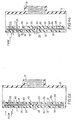
- Valve port plate 30 has a plurality of arcuate port through holes 31, also as shown in Figs. 1, 2a, 3 and 4a. Figs. 2 and 4 do not show either backer through holes 21 or port through holes 31 since the respective cross sections are taken through the center of the valve, as shown by lines 2-2 and 4-4, respectively, in Fig. 1.
- Valve port plate 30 is positioned generally parallel to valve backer plate 20 and valve port plate 30 is sealably secured with respect to valve housing 12. In one embodiment, valve port plate 30 is secured with respect to valve housing 12 by a plurality of screws 26.
- valve port plate 30 can be secured with other suitable attachment means.
- backer through holes 21 are in communication with port through holes 31. It is apparent that the flow capacity of flapper check valve 11 increases as a number and/or size of backer through holes 21 and port through holes 31 increase.
- Peripheral spacer/hermetic seal means are secured between the plates.
- the peripheral spacer/hermetic seal means are positioned about a general periphery of valve backer plate 20. It is apparent that the general periphery can be circular, polyhedral, or any other suitable shape.
- the peripheral spacer/hermetic seal means comprise peripheral spacer/hermetic seal 40 positioned at a generally peripheral location relative to valve port plate 30.
- peripheral spacer/hermetic seal 40 has an upstream side that abuts valve port plate 30 and a downstream side that abuts valve backer plate 20.
- peripheral spacer/hermetic seal 40 has an upstream side that abuts valve backer plate 20 and a downstream side that abuts valve housing 12, as shown in Fig. 2.
- upstream and “downstream” throughout this specification relate to the normal flow from valve port plate 30 to valve backer plate 20 when flapper check valve 11 is in an open position, as shown in Figs.
- peripheral spacer/hermetic seal 40 can be a one-piece spacer or can comprise a plurality of spacer pieces.
- the primary objective of peripheral spacer/hermetic seal 40 is to provide adequate peripheral support between the plates as well as to provide a hermetic seal between the plates.
- Inner spacer/flapper guide means are secured between the plates.
- the inner spacer/flapper guide means and peripheral spacer/hermetic seal means maintain a fixed distance between the plates.
- Valve backer plate 20 is secured with respect to valve port plate 30, with the inner spacer/flapper guide means between the plates, with bolt 25 or by any other suitable securing means known in the art.
- the inner spacer/flapper guide means comprise at least one flat central spacer 45 positioned at a generally central location of the plates.
- Each central spacer 45 has a uniform thickness and has an upstream side that abuts valve port plate 30 and a downstream side that abuts valve backer plate 20.
- inner spacer/flapper guide means comprise a plurality of inner spacer/guide pins 49 positioned on an interior surface of valve port plate 30.
- the interior surface is inward relative to the general periphery of valve port plate 30.
- Inner spacer/guide pins 49 provide sufficient support and stiffness to valve backer plate 20 and thus allow valve backer plate 20 and valve port plate 30 to have reduced thickness. Such support keeps valve backer plate 20 from deflecting when subjected to relatively high pressures from within valve housing 12, particulary during combustion within a pulse combustor.
- each inner spacer/guide pin 40 comprises rod 50 having central portion 51.
- Central portion 51 has a cross-sectional area greater than the cross-sectional area of outer portion 52 at each end of rod 50.
- a transition from central portion 51 to each outer portion 52 defines a shoulder that maintains a fixed distance or gap between the plates.
- Rod 50 is secured relative to valve port plate 30 and valve backer plate 20.
- Rod 50 can be secured by being press fit within either of the plates, rod 50 can be secured by being an integral part of either of the plates, rod 50 can be secured with a rivet head as shown in Fig. 1, or rod 50 can be secured by any other suitable method.
- Securing rod 50 reduces vibration and operating noise. It is apparent that other suitable spacers familiar to the art can be used to both support valve backer plate 20 and to fix the distance between the plates.
- Flapper means are freely moveable in a direction generally perpendicular to valve port plate 30.
- the flapper means move between the plates.
- Inner spacer/guide pins 49 retain the flapper means in a position such that upon a positive pressure within valve housing 12, the flapper means abut valve port plate 30 and thereby close communication between backer through holes 21 and port through holes 31.
- Backer through holes 21 allow back pressure upon combustion to force the flapper means against valve port plate 30.
- the flapper means comprise at least one flapper ring 35 secured between the plates.
- inner spacer/guide pins 49 retain each flapper ring in its respective concentric position.
- Each flapper ring 35 preferably has a uniform thickness.
- Flapper ring 35 has a ring width or ring distance, defined as the distance between an outside ring radius and an inside ring radius. The ring width or ring distance is greater than an arcuate distance, defined as the distance between an outside hole radius and an inside hole radius of a corresponding port through hole 31.
- the plates each have an overall circular shape. It is apparent that the plates can have a polyhedral shape or any other suitable shape. In one embodiment of this invention, the plates have the same dimensions. In another embodiment, valve backer plate 20 has a smaller area than valve port plate 30 and valve backer plate 20 is mounted downstream from valve port plate 30; such embodiment is specifically shown in Figs. 3, 4 and 4a.
- a multiplicity of closely and radially adjacent circular holes, over 160, are drilled into the valve port plate.
- a combination of a multiplicity of circular through holes and arcuate through holes are closely spaced in the valve backer plate.
- Such existing design requires a relatively thick plate. Thus fabrication requires expensive and burdensome machining. Such existing plates cannot be produced by stamping with a die tool.
- backer through holes 21 and port through holes 31 are sufficiently spaced within the respective plates to allow for fabrication by stamping with a die tool or other similar efficient tooling.
- flapper check valve 11 has peripheral spacer/hermetic seal means as well as inner spacer/flapper guide means, the thickness of the plates can be substantially reduced.
- the thickness of the plate according to this invention is approximately 1/2 of the thickness of existing plates of other valves having similar flow capacities.
- the reduced thickness of the plate as well as increased spacing between arcuate backer through holes 21 and increased spacing between arcuate port through holes 31 allow for sufficient surface area of the plate to position and operate die tooling.
- the flow capacity of the valve remains constant since the arcuate through holes provide more area for flow than do the circular holes of the existing art.
- the diameter of the plate as well as the spacing between the circular through holes must be increased to maintain the same flow capacity of the valve.
- backer through holes 21 are radially offset relative to port through holes 31 such that in an open position of flapper check valve 11, flapper ring 35 may abut valve backer plate 20 or float between the plates while maintaining communication between backer through holes 21 and port through holes 31.
- "Radially offset” as used in this specification relates to arcuate backer through holes 21 having offset radii with respect to adjacent rows or rings of arcuate port through holes 31.
- flapper ring 35 In a closed position of flapper check valve 11, flapper ring 35 abuts valve port plate 30 and forms a hermetic seal with respect to port through holes 31.
- Each flapper ring 35 abuts valve port plate in such a position that flapper ring 35 overlaps a radial row of port through holes 31.
- communication is closed between backer through holes 21 and port through holes 31.
- Figs. 1 and 3 show a front view of two different embodiments of flapper check valve 11 wherein the valve is divided into four quadrants to clearly show elements of the invention.
- Quadrant I shows valve housing 12 and outlet opening 13.
- Quadrant II shows valve backer plate 20.
- Quadrant III shows flapper rings 35, peripheral spacer/hermetic seal 40 and central spacer 45; flapper rings 35 are shown with hatching and peripheral spacer/hermetic seal 40 and central spacer 45 are shown with crosshatching for the purpose of clearly distinguishing the elements.
- Quadrant IV shows valve port plate 30.
- Figs. 2a and 4a illustrate backer through holes 21 and their radially offset position with respect to port through holes 31.
- valve housing 12 has internally threaded female coupling 60.
- Valve port plate 30 is secured within internal undercut 66 of externally threaded male coupling 65.
- Female coupling 60 is mateable with male coupling 65 to form a sealed joint.
- Male coupling 65 may have external coupling flats 67 for rotating male coupling 65 with respect to female coupling 60.
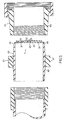
- Fig. 6 shows a cross-sectional side view of concentric flapper check valve system 70 which comprises fuel flapper check valve 72 and air flapper check valve 71.
- Fuel flapper check valve 72 has a similar construction to the above described flapper check valve 11.
- Air flapper check valve 71 also has a similar construction to flapper check valve 11 as described above, except that air flapper check valve 71 has an internal cutout section which accommodates fuel valve housing wall 74.
- Fuel valve housing wall 74 is sealably secured to an interior section of the plates of air flapper check valve 71.
- Inner peripheral air spacer 75 of air flapper check valve 71 is secured between the plates near fuel valve housing wall 74.
- concentric flapper check valve system 70 also has a flame trap 76 secured within fuel/air valve housing 73 downstream with respect to the plates.
- Flame trap 76 can be a ceramic porus plate, wound corrugated stainless steel, or any other suitable flame trap device which protects the flapper rings from high temperatures of flashback.
Landscapes
- Engineering & Computer Science (AREA)
- General Engineering & Computer Science (AREA)
- Mechanical Engineering (AREA)
- Check Valves (AREA)
Claims (19)
- Soupape de retenue à clapet comprenant une chambre de soupape (12) avec des dispositifs d'échappement;
une plaque d'appui de soupape (20) avec une multiplicité de trous de passage arqués (21);
une plaque frontale avec une multiplicité d'ouvertures d'admission arquées (31), la plaque frontale (30) étant disposée en substance parallèlement à la plaque d'appui de soupape (20) et étant fixée de manière hermétique à la chambre de soupape (12), les trous de passage (21) étant en communication avec les ouvertures d'admission (31) lorsque la soupape de retenue occupe une position d'ouverture;
des moyens d'écartement et de guidage de clapet intérieurs (45, 49), qui sont maintenus entre la plaque d'appui de soupape (20) et la plaque frontale (30), les moyens d'écartement et de guidage de clapet intérieurs (45, 49) et les moyens d'écartement et d'étanchéité extérieurs (40) établissant une distance invariable entre la plaque frontale (30) et la plaque d'appui de soupape (20);
un agencement de clapet (35) monté entre la plaque d'appui (20) et la plaque frontale (30) de manière mobile en direction perpendiculaire à la plaque frontale (30), les moyens d'écartement et d'étanchéité maintenant le clapet dans une position dans laquelle sous l'effet de la pression positive établie dans la chambre de soupape (12) le clapet (35) est appliqué contre la plaque d'appui de soupape (20), de telle sorte que la communication entre les ouvertures d'admission (31) et les trous de passage (21) est interrompue,
caractérisée
par le fait que le clapet (35) est librement mobile,
par le fait que les moyens d'écartement et de guidage de clapet intérieurs (45, 49) ont la forme de chevilles d'écartement et de guidage intérieures, chacune des chevilles d'écartement et de guidage intérieures présentant un tourillon (50) avec un tronçon médian (51), lequel a une section transversale plus grande que les deux tronçons terminaux (52),
par le fait qu'un tronçon de transition entre la tronçon médian (51) et les deux tronçons terminaux (52) constitue un épaulement, qui détermine la distance entre la plaque d'appui de soupape (20) et la plaque frontale (30), et
par le fait que le tourillon (50) est maintenu de façon verrouillée sur la plaque d'appui de soupape (20) et sur la plaque frontale (30). - Soupape de retenue à clapet suivant la revendication 1,
caractérisée
par le fait qu'un des moyens d'écartement et de guidage de clapet présente une pièce d'écartement plate centrale (45), disposée en substance dans la région centrale de la plaque d'appui de soupape (20) et de la plaque frontale,
par le fait qu'au moins une pièce d'écartement centrale (45) d'une épaisseur uniforme est prévue, et
par le fait que du côté admission, la pièce d'écartement centrale (45) est appliquée contre la plaque frontale (30), tandis que du côté d'écoulement elle est appliquée contre la plaque d'appui de soupape (20). - Soupape de retenue à clapet suivant la revendication 1,
caractérisée
par le fait que la multiplicité des chevilles d'écartement et de guidage intérieures (49) sont disposées sur une surface intérieure de la plaque d'appui de soupape et
par le fait que les chevilles d'écartement et de guidage intérieures (40) assurent un étayage suffisant de la plaque d'appui de soupape (20), de telle sorte que la plaque d'appui de soupape (20) présente une épaisseur réduite et que dans le cas d'une pression relativement élevée au sein de la chambre de soupape (12), un fléchissement de la plaque d'appui de soupape (20) est empêché. - Soupape de retenue à clapet suivant l'une quelconque des revendications de 1 à 3,
caractérisée
par le fait que les moyens d'écartement et d'étanchéité latéraux (40) ont la forme d'au moins un moyen d'écartement et d'étanchéité (40) périphérique, qui est disposé en substance dans la région latérale de la plaque d'appui de soupape et de la plaque frontale et qui du côté d'admission est appliqué contre la plaque frontale (30) et du côté écoulement est appliqué contre la plaque d'appui de soupape (20). - Soupape de retenue à clapet suivant l'une quelconque des revendications de 1 à 4,
caractérisée
par le fait que la plaque frontale (30) a dans l'ensemble une forme ronde. - Soupape de retenue à clapet suivant l'une quelconque des revendications de 1 à 5,
caractérisée
par le fait que la plaque d'appui de soupape (20) a dans l'ensemble une forme ronde. - Soupape de retenue à clapet suivant l'une quelconque des revendications de 1 à 6,
caractérisée
par le fait que l'agencement de clapet (35) présente au moins un anneau de clapet,
par le fait que chaque anneau de clapet présente une épaisseur uniforme, et
par le fait la largeur d'anneau entre un rayon d'anneau extérieur et un rayon d'anneau intérieur est supérieure à la distance arquée entre un rayon de trou extérieur et un rayon de trou intérieur d'une ouverture d'admission arquée correspondante (31). - Soupape de retenue à clapet suivant la revendication 7,
caractérisée
par le fait que les anneaux de clapet sont guidés sur les chevilles d'écartement et de guidage intérieures (49). - Soupape de retenue à clapet suivant l'une quelconque des revendications de 1 à 8,
caractérisée
par le fait que les trous de passage (21) au sein de la plaque d'appui de soupape (20) sont suffisamment éloignés les uns des autres, de telle sorte que la plaque d'appui de soupape (20) peut être usinée au moyen d'un outil d'estampage. - Soupape de retenue à clapet suivant la revendication 1,
caractérisée
par le fait que les trous d'admission (31) au sein de la plaque frontale (30) sont suffisamment éloignés les uns des autres, de telle sorte que la plaque frontale (30) peut être usinée au moyen d'un outil d'estampage. - Soupape de retenue à clapet suivant l'une quelconque des revendications de 1 à 10,
caractérisée
par le fait que les trous de passage arqués (21) sont décalés radialement par rapport aux ouvertures d'admission arquées (31), de telle sorte que dans la position d'ouverture de la soupape de retenue à clapet, l'agencement de clapet (35) est appliqué contre la plaque d'appui de soupape (20) et établit la communication entre les ouvertures d'admission (31) et les trous de passage, et
par le fait que dans la position de fermeture de la soupape de retenue à clapet, l'agencement de clapet (35) est appliqué contre la plaque frontale (30) et interrompt la communication entre les ouvertures d'admission et les trous de passage. - Soupape de retenue à clapet suivant l'une quelconque des revendications de 1 à 6,
caractérisée
par le fait que l'agencement de clapet (35) présente au moins un anneau de clapet d'une largeur d'anneau comprise entre un rayon d'anneau extérieur et un rayon d'anneau intérieur, largeur qui est plus grande que la distance arquée entre un rayon de trou extérieur et un rayon de trou intérieur d'une ouverture d'admission arquée associée. - Soupape de retenue à clapet suivant l'une quelconque des revendications de 1 à 12,
caractérisée
par le fait que la plaque d'appui de soupape (20) et la plaque frontale (30) présentent les mêmes dimensions. - Soupape de retenue à clapet suivant l'une quelconque des revendications de 1 à 13,
caractérisée
par le fait que la plaque frontale (30) est fixée à la chambre de soupape (12) et
par le fait que par rapport à la plaque frontale (30) la plaque d'appui de soupape (20) est disposée en aval et est fixée dans la chambre de soupape (12). - Soupape de retenue à clapet suivant la revendication 14,
caractérisée
par le fait qu'au moins un moyen d'écartement et d'étanchéité latéral (49) est prévu, lequel est disposé en substance dans la région marginale de la plaque d'appui de soupape (20), et par le fait que ledit moyen d'écartement et d'étanchéité (40) est, côté admission, appliqué contre la plaque frontale (30) et est, côté évacuation, appliqué contre la plaque d'appui de soupape (20). - Soupape de retenue à clapet suivant l'une quelconque des revendications de 1 à 15,
caractérisée
par le fait que le dispositif d'échappement (13) comprend la chambre de soupape et au moins une ouverture d'échappement. - Soupape de retenue suivant la revendication 1, caractérisée
par le fait la chambre de soupape (12) présente un élément d'accouplement (60) avec un filetage intérieur,
par le fait que la plaque frontale (30) est maintenue dans un évidement (66) d'un élément d'accouplement supplémentaire (65) avec un filetage extérieur et
par le fait que l'élément d'accouplement (60) avec le filetage intérieur peut être relié à l'élément d'accouplement avec le filetage extérieur pour constituer une unité hermétique. - Système concentrique de soupape de retenue à clapet (70) avec une soupape de retenue de combustible (72) et avec une soupape de retenue d'air (71), la soupape de retenue de combustible (72) présentant les éléments suivants:
une chambre de soupape de combustible;
une plaque d'appui de soupape de combustible avec une multiplicité d'ouvertures de passage de combustible arquées;
une plaque frontale de combustible avec une multiplicité d'ouvertures d'admission de combustible arquées, la plaque frontale de combustible étant disposée en substance parallèlement à la plaque d'appui de soupape de combustible et étant fixée de manière hermétique à la chambre de soupape de combustible, les trous de passage de combustible étant en communication avec les ouvertures d'admission de combustible lorsque la soupape de retenue de combustible occupe une position d'ouverture;
des pièces d'écartement latérales, qui sont maintenues entre la plaque d'appui de soupape de combustible et la plaque frontale de combustible, les pièces d'écartement latérales étant disposées en substance autour d'une périphérie de soupape de combustible de la plaque d'appui de soupape de combustible;
des pièces d'écartement intérieures, qui sont disposées entre la plaque frontale de combustible et la plaque d'appui de soupape de combustible, les pièces d'écartement intérieures et les pièces d'écartement latérales déterminant une première distance invariable entre la plaque frontale de combustible et la plaque d'appui de soupape de combustible, les dispositifs d'écartement et de guidage de clapet présentant un grand nombre de chevilles de guidage et d'écartement intérieures, lesquelles sont disposées sur la surface intérieure de la plaque frontale par rapport à sa région latérale, les chevilles d'écartement et de guidage intérieures assurant un étayage suffisant de la plaque d'appui de soupape, de telle sorte que la plaque d'appui de soupape peut présenter une épaisseur réduite et peut , dans le cas d'une pression relativement élevée au sein de la chambre de soupape, prévenir un fléchissement de la plaque d'appui de soupape;
un agencement de clapet de combustible librement mobile dans une direction perpendiculaire à la plaque frontale de combustible, agencement disposé entre la plaque d'appui de soupape de combustible et la plaque frontale de combustible, les pièces d'écartement intérieures assujettissant dans une première position l'agencement de clapet de combustible, de telle sorte que sous l'effet d'une pression positive au sein de la chambre de soupape d'air de combustible l'agencement de clapet de combustible est appliqué contre la plaque frontale de combustible et interrompt dès lors la communication entre les trous de passage de combustible et les ouvertures d'admission de combustible, et
système dans lequel la soupape de retenue de clapet d'air (71) présente :
une chambre de soupape de combustible et d'air;
une plaque d'appui de soupape d'air avec une multiplicité de trous de passage d'air en forme d'arc;
une plaque frontale d'air avec une multiplicité d'ouvertures d'admission d'air en forme d'arc, la plaque frontale d'air étant disposée en substance parallèlement à la plaque d'appui de soupape d'air et étant fixée de manière hermétique à la chambre de soupape de combustible et d'air, les ouvertures d'admission d'air étant en communication avec les trous de passage d'air lorsque la soupape de retenue de clapet d'air (71) occupe une position d'ouverture;
des pièces d'écartement latérales extérieures, qui sont maintenues entre la plaque d'appui de soupape d'air et la plaque frontale d'air, les pièces d'écartement latérales étant disposées en substance autour d'une périphérie de soupape de la plaque d'appui de soupape d'air;
des pièces d'écartement intérieures, qui sont disposées entre la plaque frontale d'air et la plaque d'appui de soupape d'air, les pièces d'écartement latérales intérieures et extérieures établissant une deuxième distance invariable entre la plaque frontale d'air et la plaque d'appui de soupape d'air, les pièces d'écartement intérieures présentant une pièce d'écartement latérale intérieure qui est disposée entre la plaque frontale d'air et la plaque d'appui de soupape d'air dans la région d'une paroi de chambre de soupape de combustible (74);
un agencement de clapet d'air, disposé de manière librement mobile dans une deuxième direction en substance perpendiculairement à la plaque frontale d'air entre la plaque frontale d'air et la plaque d'appui de soupape d'air, les pièces d'écartement latérales intérieures assujettissant l'agencement de clapet d'air dans une deuxième position, pour laquelle sous l'effet d'une pression positive au sein de la chambre de soupape d'air de combustible, l'agencement de clapet d'air est appliqué contre la plaque frontale d'air et interrompt de la sorte la communication entre les ouvertures de passage d'air et les ouvertures d'admission d'air; et
dans lequel la chambre de soupape de combustible présente une paroi de chambre de soupape (74), qui est maintenue de manière hermétique dans une région intérieure de la plaque d'appui de soupape d'air et la plaque frontale d'air. - Soupape de retenue à clapet concentrique suivant la revendication 18,
caractérisée
par le fait que dans la chambre de soupape d'air et de combustible est prévue une sécurité contre le retour de flamme (76) et
par le fait que par rapport à la plaque d'appui de soupape de combustible et par rapport à la plaque d'appui de soupape d'air, la sécurité contre le retour de flamme (76) est disposée en aval.
Applications Claiming Priority (2)
| Application Number | Priority Date | Filing Date | Title |
|---|---|---|---|
| US07/359,082 US4951706A (en) | 1989-05-26 | 1989-05-26 | Flapper check valve |
| US359082 | 1989-05-26 |
Publications (2)
| Publication Number | Publication Date |
|---|---|
| EP0399443A1 EP0399443A1 (fr) | 1990-11-28 |
| EP0399443B1 true EP0399443B1 (fr) | 1993-12-29 |
Family
ID=23412235
Family Applications (1)
| Application Number | Title | Priority Date | Filing Date |
|---|---|---|---|
| EP19900109650 Expired - Lifetime EP0399443B1 (fr) | 1989-05-26 | 1990-05-21 | Soupape de retenue avec plaque de déviation |
Country Status (4)
| Country | Link |
|---|---|
| US (1) | US4951706A (fr) |
| EP (1) | EP0399443B1 (fr) |
| CA (1) | CA2017371C (fr) |
| DE (1) | DE69005523T2 (fr) |
Families Citing this family (10)
| Publication number | Priority date | Publication date | Assignee | Title |
|---|---|---|---|---|
| US6196164B1 (en) * | 1995-04-04 | 2001-03-06 | Srp 687 Pty. Ltd. | Ignition inhibiting gas water heater |
| ES2140865T3 (es) * | 1995-05-05 | 2000-03-01 | Sorelec | Bomba alternativa vertical. |
| US7004734B2 (en) * | 1999-12-28 | 2006-02-28 | Zexel Valco Climate Control Corporation | Reciprocating refrigerant compressor |
| US6442936B1 (en) * | 2000-12-14 | 2002-09-03 | Caterpillar Inc. | Single stage or multi-stage compressor for a turbocharger |
| US7309155B2 (en) * | 2003-09-26 | 2007-12-18 | Consolidated Environmental Technologies, Ltd. | Tank mixing system and valve therefor |
| US9115794B2 (en) | 2012-07-06 | 2015-08-25 | Hamilton Sundstrand Corporation | Integrated drive generator pump plate |
| JP7165670B6 (ja) * | 2017-03-27 | 2023-08-18 | ブルクハルト コンプレッション アーゲー | ピストンコンプレッサバルブ用のバルブクロージャおよびそのバルブクロージャを動作させるための方法 |
| EP3601799B1 (fr) * | 2017-03-27 | 2023-01-11 | Burckhardt Compression AG | Soupape de compresseur à piston et son procédé de fonctionnement |
| JP7362637B2 (ja) * | 2018-03-08 | 2023-10-17 | ブルクハルト コンプレッション アーゲー | 板弁およびその作動方法 |
| US11913556B2 (en) * | 2022-07-01 | 2024-02-27 | Siemens Energy, Inc. | Anti-spin outer diameter guided compressor valve |
Citations (2)
| Publication number | Priority date | Publication date | Assignee | Title |
|---|---|---|---|---|
| EP0210287A1 (fr) * | 1985-07-20 | 1987-02-04 | Dienes Werke Für Maschinenteile Gmbh & Co Kg | Soupape à lamelles avec bras de guidage concentriques |
| EP0300989A1 (fr) * | 1987-07-01 | 1989-01-25 | ENFO Grundlagenforschungs AG | Soupape à plateau pour compresseur |
Family Cites Families (31)
| Publication number | Priority date | Publication date | Assignee | Title |
|---|---|---|---|---|
| US1102647A (en) * | 1912-08-12 | 1914-07-07 | Charles B Davis | Brewing apparatus, &c. |
| US1121969A (en) * | 1914-04-06 | 1914-12-22 | Ernst Beling | Safety device for muffles, cupolas, and other furnaces. |
| US1243122A (en) * | 1917-05-22 | 1917-10-16 | David L Winters | Valve. |
| US1909974A (en) * | 1930-08-12 | 1933-05-23 | Ingersoll Rand Co | Valve mechanism |
| US2124323A (en) * | 1937-04-07 | 1938-07-19 | Johann H H Voss | Ring plate valve |
| US2898978A (en) * | 1956-02-20 | 1959-08-11 | Lucas Rotax Ltd | Gaseous fuel combustion apparatus |
| US3005485A (en) * | 1958-05-07 | 1961-10-24 | Lucas Industries Ltd | Gaseous fuel combustion apparatus |
| US3162699A (en) * | 1961-02-13 | 1964-12-22 | Robert B Sivyer | Vapor liquid contacting apparatus |
| AT240509B (de) * | 1963-01-17 | 1965-06-10 | Hoerbiger Ventilwerke Ag | Plattenventil |
| US3358710A (en) * | 1964-04-01 | 1967-12-19 | Dresser Ind | Valve construction for reciprocating type compressor |
| US3312241A (en) * | 1964-04-16 | 1967-04-04 | Westinghouse Electric Corp | Fluid control apparatus |
| US3357449A (en) * | 1965-06-24 | 1967-12-12 | Chicago Pneumatic Tool Co | Valve unit for non-lube air compressors |
| US3536094A (en) * | 1968-03-12 | 1970-10-27 | Flavious E Manley Jr | Compressor valve |
| US3853268A (en) * | 1971-03-11 | 1974-12-10 | Rau Fa G | Temperature responsive valves |
| US3786834A (en) * | 1972-06-21 | 1974-01-22 | Frick Co | Multiple wave form spring valve assembly |
| US4173985A (en) * | 1977-07-08 | 1979-11-13 | Kirpichenkov Alexandr G | Straightway valve |
| US4278106A (en) * | 1979-09-20 | 1981-07-14 | Cunningham William W | Plate check valve |
| US4300595A (en) * | 1979-11-28 | 1981-11-17 | The Bendix Corporation | Solenoid control valve |
| US4307751A (en) * | 1979-11-29 | 1981-12-29 | Edison International, Inc. | Plate valve |
| US4336791A (en) * | 1980-05-12 | 1982-06-29 | Kitchhen John A | Pulse combustion apparatus |
| US4577661A (en) * | 1981-12-14 | 1986-03-25 | Ingersoll-Rand Company | High speed-high flow spool valve |
| JPS599416A (ja) * | 1982-07-09 | 1984-01-18 | Matsushita Electric Ind Co Ltd | パルス燃焼器 |
| US4483363A (en) * | 1983-09-21 | 1984-11-20 | Madoche Robert D | Compressor valve |
| DE3339441C2 (de) * | 1983-10-29 | 1986-06-12 | Schubert & Salzer Maschinenfabrik Ag, 8070 Ingolstadt | Schieberventil |
| JPS60160315U (ja) * | 1984-03-30 | 1985-10-24 | 株式会社東芝 | パルス燃焼装置 |
| US4537213A (en) * | 1984-08-27 | 1985-08-27 | Molina Domingo F | Double flapper check valve |
| US4569208A (en) * | 1984-12-07 | 1986-02-11 | Buildex Incorporated | Pressure relief port |
| US4570610A (en) * | 1984-12-28 | 1986-02-18 | Gas Research Institute | Pulse combustion burner for cooking surface |
| US4640674A (en) * | 1986-01-02 | 1987-02-03 | John A. Kitchen Ltd. | Pulse combustion apparatus |
| JPH033763Y2 (fr) * | 1986-01-28 | 1991-01-31 | ||
| US4752209A (en) * | 1987-01-23 | 1988-06-21 | American Gas Association | Pulse combustion burner feed valve |
-
1989
- 1989-05-26 US US07/359,082 patent/US4951706A/en not_active Expired - Lifetime
-
1990
- 1990-05-21 DE DE90109650T patent/DE69005523T2/de not_active Expired - Fee Related
- 1990-05-21 EP EP19900109650 patent/EP0399443B1/fr not_active Expired - Lifetime
- 1990-05-23 CA CA 2017371 patent/CA2017371C/fr not_active Expired - Fee Related
Patent Citations (2)
| Publication number | Priority date | Publication date | Assignee | Title |
|---|---|---|---|---|
| EP0210287A1 (fr) * | 1985-07-20 | 1987-02-04 | Dienes Werke Für Maschinenteile Gmbh & Co Kg | Soupape à lamelles avec bras de guidage concentriques |
| EP0300989A1 (fr) * | 1987-07-01 | 1989-01-25 | ENFO Grundlagenforschungs AG | Soupape à plateau pour compresseur |
Also Published As
| Publication number | Publication date |
|---|---|
| EP0399443A1 (fr) | 1990-11-28 |
| CA2017371C (fr) | 1993-10-05 |
| US4951706A (en) | 1990-08-28 |
| DE69005523T2 (de) | 1994-04-21 |
| DE69005523D1 (de) | 1994-02-10 |
| CA2017371A1 (fr) | 1990-11-26 |
Similar Documents
| Publication | Publication Date | Title |
|---|---|---|
| US4951706A (en) | Flapper check valve | |
| EP1488151B1 (fr) | Dispositif de reduction des bruits pour systemes d'ecoulement fluidique | |
| EP1300619B1 (fr) | Clapet integre a un orifice | |
| AU692015B2 (en) | Compressor valve | |
| EP2140180B1 (fr) | Soupape à bille dotée d'un moyen amovible servant à retenir le joint axial | |
| CN102359612B (zh) | 用于压力调节器的流动限制座环 | |
| EP1160511B1 (fr) | Ensemble de clapet de dérivation dans une turbine à gaz | |
| EP1586350B1 (fr) | Pare-flamme | |
| EP4080094B1 (fr) | Robinet à tournant sphérique | |
| CA1256013A (fr) | Dispositif de combustion pulsee | |
| US11562726B2 (en) | Plates and plate assemblies for noise attenuators and other devices and methods making the same | |
| US20040034998A1 (en) | Vane and method of construction thereof | |
| EP1403584B1 (fr) | Joint de turbine de type pince à ressort | |
| US11282491B2 (en) | Plates and plate assemblies for noise attenuators and other devices and methods making the same | |
| US4177970A (en) | Valve assembly for use in an air distribution system | |
| US4752209A (en) | Pulse combustion burner feed valve | |
| CN101372991A (zh) | 模块化表面安装的流体系统 | |
| US4249566A (en) | Fluid pressure-operated valves | |
| CN101107449B (zh) | 具有选择性可变节流孔的气动装置 | |
| AU3893799A (en) | A method for fabricating a turbine inlet casing and the turbine inlet casing | |
| CN224229249U (zh) | 一种阀芯外置阀座内导向结构调节阀 | |
| EP0014277A1 (fr) | Clapet commandé par pression de fluide | |
| US12372167B2 (en) | Anti-cavitation valve assembly | |
| EP4090867B1 (fr) | Dispositif d'écoulement de fluide | |
| CA1119502A (fr) | Soupapes commandees par fluide |
Legal Events
| Date | Code | Title | Description |
|---|---|---|---|
| PUAI | Public reference made under article 153(3) epc to a published international application that has entered the european phase |
Free format text: ORIGINAL CODE: 0009012 |
|
| AK | Designated contracting states |
Kind code of ref document: A1 Designated state(s): BE CH DE FR GB IT LI NL SE |
|
| 17P | Request for examination filed |
Effective date: 19901108 |
|
| 17Q | First examination report despatched |
Effective date: 19920630 |
|
| GRAA | (expected) grant |
Free format text: ORIGINAL CODE: 0009210 |
|
| AK | Designated contracting states |
Kind code of ref document: B1 Designated state(s): BE CH DE FR GB IT LI NL SE |
|
| PG25 | Lapsed in a contracting state [announced via postgrant information from national office to epo] |
Ref country code: IT Free format text: LAPSE BECAUSE OF FAILURE TO SUBMIT A TRANSLATION OF THE DESCRIPTION OR TO PAY THE FEE WITHIN THE PRE;WARNING: LAPSES OF ITALIAN PATENTS WITH EFFECTIVE DATE BEFORE 2007 MAY HAVE OCCURRED AT ANY TIME BEFORE 2007. THE CORRECT EFFECTIVE DATE MAY BE DIFFERENT FROM THE ONE RECORDED.SCRIBED TIME-LIMIT Effective date: 19931229 Ref country code: CH Effective date: 19931229 Ref country code: SE Effective date: 19931229 Ref country code: LI Effective date: 19931229 Ref country code: BE Effective date: 19931229 Ref country code: FR Effective date: 19931229 |
|
| REF | Corresponds to: |
Ref document number: 69005523 Country of ref document: DE Date of ref document: 19940210 |
|
| REG | Reference to a national code |
Ref country code: CH Ref legal event code: PL |
|
| EN | Fr: translation not filed | ||
| PLBE | No opposition filed within time limit |
Free format text: ORIGINAL CODE: 0009261 |
|
| STAA | Information on the status of an ep patent application or granted ep patent |
Free format text: STATUS: NO OPPOSITION FILED WITHIN TIME LIMIT |
|
| 26N | No opposition filed | ||
| PGFP | Annual fee paid to national office [announced via postgrant information from national office to epo] |
Ref country code: GB Payment date: 19990527 Year of fee payment: 10 |
|
| PGFP | Annual fee paid to national office [announced via postgrant information from national office to epo] |
Ref country code: NL Payment date: 19990531 Year of fee payment: 10 |
|
| PGFP | Annual fee paid to national office [announced via postgrant information from national office to epo] |
Ref country code: DE Payment date: 19990609 Year of fee payment: 10 |
|
| PG25 | Lapsed in a contracting state [announced via postgrant information from national office to epo] |
Ref country code: GB Free format text: LAPSE BECAUSE OF NON-PAYMENT OF DUE FEES Effective date: 20000521 |
|
| PG25 | Lapsed in a contracting state [announced via postgrant information from national office to epo] |
Ref country code: NL Free format text: LAPSE BECAUSE OF NON-PAYMENT OF DUE FEES Effective date: 20001201 |
|
| GBPC | Gb: european patent ceased through non-payment of renewal fee |
Effective date: 20000521 |
|
| NLV4 | Nl: lapsed or anulled due to non-payment of the annual fee |
Effective date: 20001201 |
|
| PG25 | Lapsed in a contracting state [announced via postgrant information from national office to epo] |
Ref country code: DE Free format text: LAPSE BECAUSE OF NON-PAYMENT OF DUE FEES Effective date: 20010301 |