EP0399466A2 - Boîte dynamométrique - Google Patents
Boîte dynamométrique Download PDFInfo
- Publication number
- EP0399466A2 EP0399466A2 EP90109701A EP90109701A EP0399466A2 EP 0399466 A2 EP0399466 A2 EP 0399466A2 EP 90109701 A EP90109701 A EP 90109701A EP 90109701 A EP90109701 A EP 90109701A EP 0399466 A2 EP0399466 A2 EP 0399466A2
- Authority
- EP
- European Patent Office
- Prior art keywords
- strain
- load
- moisture
- load cell
- attached
- Prior art date
- Legal status (The legal status is an assumption and is not a legal conclusion. Google has not performed a legal analysis and makes no representation as to the accuracy of the status listed.)
- Withdrawn
Links
Images

Classifications
-
- G—PHYSICS
- G01—MEASURING; TESTING
- G01L—MEASURING FORCE, STRESS, TORQUE, WORK, MECHANICAL POWER, MECHANICAL EFFICIENCY, OR FLUID PRESSURE
- G01L1/00—Measuring force or stress, in general
- G01L1/20—Measuring force or stress, in general by measuring variations in ohmic resistance of solid materials or of electrically-conductive fluids; by making use of electrokinetic cells, i.e. liquid-containing cells wherein an electrical potential is produced or varied upon the application of stress
- G01L1/22—Measuring force or stress, in general by measuring variations in ohmic resistance of solid materials or of electrically-conductive fluids; by making use of electrokinetic cells, i.e. liquid-containing cells wherein an electrical potential is produced or varied upon the application of stress using resistance strain gauges
- G01L1/2206—Special supports with preselected places to mount the resistance strain gauges; Mounting of supports
- G01L1/2243—Special supports with preselected places to mount the resistance strain gauges; Mounting of supports the supports being parallelogram-shaped
-
- G—PHYSICS
- G01—MEASURING; TESTING
- G01G—WEIGHING
- G01G3/00—Weighing apparatus characterised by the use of elastically-deformable members, e.g. spring balances
- G01G3/12—Weighing apparatus characterised by the use of elastically-deformable members, e.g. spring balances wherein the weighing element is in the form of a solid body stressed by pressure or tension during weighing
- G01G3/14—Weighing apparatus characterised by the use of elastically-deformable members, e.g. spring balances wherein the weighing element is in the form of a solid body stressed by pressure or tension during weighing measuring variations of electrical resistance
- G01G3/1402—Special supports with preselected places to mount the resistance strain gauges; Mounting of supports
- G01G3/1412—Special supports with preselected places to mount the resistance strain gauges; Mounting of supports the supports being parallelogram shaped
-
- G—PHYSICS
- G01—MEASURING; TESTING
- G01L—MEASURING FORCE, STRESS, TORQUE, WORK, MECHANICAL POWER, MECHANICAL EFFICIENCY, OR FLUID PRESSURE
- G01L1/00—Measuring force or stress, in general
- G01L1/20—Measuring force or stress, in general by measuring variations in ohmic resistance of solid materials or of electrically-conductive fluids; by making use of electrokinetic cells, i.e. liquid-containing cells wherein an electrical potential is produced or varied upon the application of stress
- G01L1/22—Measuring force or stress, in general by measuring variations in ohmic resistance of solid materials or of electrically-conductive fluids; by making use of electrokinetic cells, i.e. liquid-containing cells wherein an electrical potential is produced or varied upon the application of stress using resistance strain gauges
- G01L1/2287—Measuring force or stress, in general by measuring variations in ohmic resistance of solid materials or of electrically-conductive fluids; by making use of electrokinetic cells, i.e. liquid-containing cells wherein an electrical potential is produced or varied upon the application of stress using resistance strain gauges constructional details of the strain gauges
Definitions
- This invention relates to load cells used in electronic scales and other weighing apparatus and, more particularly, to such load cells having improved moisture-proofing means.
- a cantilever-type load cell which is commonly used in electronic scales generally comprises a load-sensitive element having an upper beam and a lower beam forming a pair. Two strain-generating parts are formed on each of these two beams and strain-detecting elements such as strain gauges are attached individually to such strain-generating parts on the beams so as to measure the tensile and compressive strains at these parts caused by a load applied to the load-sensitive element and to thereby determine the magnitude of the load itself.
- Moisture-proofing means are sometimes provided to these strain-detecting elements of a load cell of this type in order to protect these elements against moisture and humidity and to thereby enhance their durability.
- Examples of moisture-proofing method which has been tried include covering the elements by a material such as silicone rubber and butyl rubber.
- Such organic polymer materials are moisture-permeable to a certain extent because of their molecular structures. Although they do not totally lack in moisture-proofing effect, they are not sufficiently effective especially when the load cell is used in a very humid or moist environment.
- Japanese Utility Model Publication Jikkai 59-183639 discloses a method of providing water-proofing putty on such beams above and below the load-sensitive element around the positions where strain-detecting elements are to be attached such that water-proofing sheets placed thereover can tightly seal the strain-detecting elements with a space provided therearound.
- a load cell embodying the present invention with which the above and other objects can be achieved may be characterized as being a cantilever-type with an upper beam and a lower beam, each of these beams having formed thereon a pair of strain-generating parts adapted to generate a strain corresponding to an applied load.
- Either one of these two beams has an indented part formed on its surface, the indented part being lower than the edge parts therearound.
- Strain-detecting elements are attached to the bottom surface of this indented part at positions corresponding to the strain-generating parts and covered by a moisture-proof material.
- the interior of the indented part is completely sealed by a moisture-proof sheet which is attached to only small areas of this beam but not to the moisture-proof material so as not to significantly interfere with the deformation of the cell.
- strain-detecting elements When a load is applied to a load cell thus structured, tensile and compressive strains generated correspondingly to the load at the strain-generating parts are detected by the strain-detecting elements and the load is calculated on the basis of these detected strains. Since the strain-detecting elements are all attached to the bottom surface of the indented part and the interior of this indented part is completely sealed by a moisture-proof sheet, these elements are well protected against humidity and moisture. In particular, since this indented part and the moisture-proof sheet are provided to only one of the beams, both the production cost of the load cell and the interfering effect of the moisture-proof sheet on the free deformation of the load cell are significantly reduced. Moreover, since a plurality of strain-detecting elements are protected against humidity and moisture by a single moisture-proofing means, occurrence of problems related to durability caused by defective moisture-proofing can also be reduced significantly.
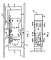
- numeral 1 indicates a load cell embodying the present invention.
- Numeral 10 indicates a load-sensitive element which serves as the main body of this load cell 1 and has a hollow, rectangular configuration with a rigid fixed portion 11 on the left-hand side (with reference to Fig. 1), a rigid movable portion 12 on the right-hand side (with reference also to Fig. 1) and a pair of upper and lower beams 13 and 14 between these two rigid portions 11 and 12.
- the rigid fixed portion 11 might be affixed to the main structure 3 of the scale by a bracket 2 and a tray 4 to the rigid movable portion 12 by another bracket 3.
- the beam widths are reduced by the formation of semicircular cutouts on the inner sides of the beams 13 and 14 to define strain-generating parts 13a, 13b, 14a and 14b as shown in Fig. 1.
- the upper surface of the upper beam 13 is provided with an indented part 15 which includes both the strain-generating parts 13a and 13b and is lower than its surrounding sections.
- a total of four strain gauges 21 is attached to the top of the load-sensitive element 10 on the bottom surface of the indented part 15.
- Lead lines (not shown) connected individually to these strain gauges 21 are passed through throughholes 16 and taken out through both side surfaces of the rigid fixed portion 11. These throughholes 16 are eventually filled with a moisture-proof filler material after these lead lines are passed therethrough.
- the longitudinal side edges 10a of the entire top surface of the load-sensitive element 10 inclusive of the rigid portions 11 and 12 and the upper beam 13 are rounded.
- the thickness x of the upper beam 13 at the strain-generating parts 13a and 13b as measured from the bottom surface of the indented part 15 is made somewhat smaller than the thickness y of the lower beam 14 at the strain-generating parts 14a and 14b.
- the four strain gauges 21 form a Wheatstone bridge circuit as shown in Fig. 4 such that an output voltage e is obtained from a specified input voltage E according to the changes in resistance of the individual strain gauges 21.
- the strain gauges 211 and 212 proximal to the rigid fixed portion 11 experience tensile strains and the strain gauges 213 and 214 proximal to the rigid movable portion 12 experience compressive strains when a load is applied to the load cell 1.
- these strain gauges 21 are connected as shown in Fig. 4.
- the load cell 1 is further provided with moisture-proofing means for protecting its strain gauges 21 from humidity and moisture.
- a moisture-proofing material 22 such as silicone rubber or butyl rubber which is applied thereon but a small piece of a polymer film such as polytetrafluoroethylene (Teflon) or a composite metallic foil-polymer film formed with metallic foil (for example, of aluminum) over a moisture-proof polymer film of polyester, polypropylene, polyethylene or the like (hereinafter generally referred to as a covering member 23 whether the polymer film is laminated or not laminated with a metallic foil) is attached to this moisture-proofing material 22 from above.
- a covering member 23 whether the polymer film is laminated or not laminated with a metallic foil
- the indented part 15 itself is tightly sealed by a moisture-proof sheet 24 of a composite metallic foil-polymer film of the type described above which is attached to the top surface of the load-sensitive element 10 by applying an adhesive only on the frame-shaped area shown shaded in Fig. 5. Described more in detail with reference to Fig. 5, the adhesive is applied only on the frame-shaped area which surrounds the indented part 15 and includes top sections X1 on the side surfaces of the load-sensitive element 10 and edge sections X2 extending transversely in the direction of the width over the top surface of the load-sensitive element 10 along the transverse side edges of the indented part 15. In other words, this moisture-proof sheet 24 is not adhesively attached to the aforementioned longitudinally extending edge parts 10b on both sides of the indented part 15.
- the resistance values of the individual strain gauges 21 are thereby changed and a voltage e indicative of the load (that is, the weight of the article being weighed) is outputted from the Wheatstone bridge circuit shown in Fig. 4.
- the desired weight value can be calculated from the measured value of this output voltage e.
- strain gauges 21 contained inside the indented part 15 are covered by a moisture-proof material 22 such as silicone rubber and the indented part 15 itself is sealed by a moisture-proof sheet 24 of a metallic foil-polymer film of the type described above, these strain gauges 21 may be said to be doubly protected from external humidity and moisture, providing improved durability even if the load cell 1 is used in a particularly humid and moist environment. Since the strain gauges 21 are all inside the single indented part 15 on the upper beam 13 according to the present invention, only a single moisture-proofing means is required to protect all the strain gauges 21 together. In other words, moisture-proofing is effected more efficiently according to the present invention than if strain gauges were attached to both the upper and lower beams.
- the sheet tends to interfere with the free deformation of the load-sensitive element so as to adversely affect the accuracy of measurement of a load by the load cell.
- the strain gauges 21 are disposed only on the upper beam 13 and the moisture-proof sheet 24 is attached only to the upper beam 13, the total effect of the aforementioned interference with the free deformation of is significantly less than if moisture-proof sheets are attached to both the upper and lower beams. As a result, strains are obtained more accurately corresponding to the load at the strain-generating parts 13a, 13b, 14a and 14b according to the present invention.
- the moisture-proof sheet 24 is attached to the top surface of the load-sensitive element 10 only through relatively small sections (X2).
- X2 relatively small sections
- the strain gauges 211 - 214 all experience a tensile strain. In such a situation, the changes in resistance of the strain gauges caused by these strains and the effect of the moisture-proof sheet 24 tend to cancel each other. Accordingly, it is advantageous to have all strain gauges attached to one of the beams from the point of view of accuracy of measurement in the case of an eccentrically applied load.
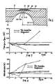
- Fig. 7 relates to the rate of change in the span, that is, the difference in the output between the no-load situation and when a load of 15Kg is applied as compared to its initial value
- Fig. 8 relates to the rate of change in the zero-point, that is, the output value under a no-load condition as compared to its initial value.
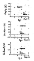
- Figs. 9-11 are the results of tests for showing the effects of not attaching the moisture-proof sheet to the top surface of the load-sensitive element.
- Fig. 9 relates to creep tests wherein the input voltage was 12V, a load of 15Kg was applied for 30 minutes and the difference between the output value under a no-load condition and that with the load of 15Kg after the test (the span) was compared with the initial value.
- Fig. 9 relates to creep tests wherein the input voltage was 12V, a load of 15Kg was applied for 30 minutes and the difference between the output value under a no-load condition and that with the load of 15Kg after the test (the span) was compared with the initial value.
- Fig. 10 relates to zero-return tests wherein the zero point after a load was applied under the same conditions as above and its change from the initial value was observed.
- Fig. 11 relates to non-linearity tests wherein a straight line was drawn between the output value under a no-load condition and the output when a load of 15Kg was applied and the maximum deviation from this straight line among the output values when the applied load was 3Kg, 6Kg, 9Kg and 12Kg was obtained by taking the effects of hysteresis into consideration.
- Figs. 9-11 show that the effects of not attaching the moisture-proof sheet directly to the top surface of the load-sensitive element are clearly visible in all of these tests.
- the longitudinally extending edge parts 10b are rounded. This is for preventing the moisture-proof sheet 24 from becoming damaged by a sharp edge.
- the purpose of the covering member 23 shown in Fig. 6 and made of a Teflon sheet or a piece of a metallic foil-polymer film of the type described above is to prevent the moisture-proof material 22, which is usually sticky, from becoming attached by its own stickiness to the moisture-proof sheet 24 disposed thereabove. It is further to be noted, as shown in Fig. 6, that the strain gauges 21 are not attached exactly at the strain-generating parts 13a and 13b defined as the parts where the thickness of the upper beam is the smallest.
- the strain gauges 21 are slightly displaced from the strain-generating parts 13a and 13b by a specified distance Z towards the edge of the load-sensitive element 10. This is because, in the case of a load cell having strain gauges attached to only one beam on one side of the its load-sensitive element, a linear relationship between applied load and output voltage is not obtained if the strain gauges are disposed exactly at the strain-generating parts, while a good linearity relationship can be obtained if the strain gauges are attached, as shown in Fig. 6, slightly displaced from the strain-generating parts towards the nearer edge of the load-sensitive element.
- strain gauges 21 and the means for protecting them against humidity and moisture are all provided on the upper surface of the upper beam 13 according to the embodiment described above, they may be provided instead on the lower surface of the lower beam 14.
- semicircular indentations for providing strain-generating parts may be formed on the upper surface of the upper beam 13 and the lower surface of the lower beam 14. With strain-generating parts thus formed, strain gauges 21 and means for their protection may be attached to the lower surface of the upper beam 13 or the upper surface of the lower beam 14 although such alternatives are not illustrated.
- FIG. 2 shows two strain gauges 21 at each of the two strain-generating parts 13a and 13b on the upper beam 13, it is possible to attach only one strain gauge at each of two strain-generating parts on either the upper beam 13 or the lower beam 14.
Landscapes
- Physics & Mathematics (AREA)
- General Physics & Mathematics (AREA)
- Measurement Of Force In General (AREA)
- Measurement Of Length, Angles, Or The Like Using Electric Or Magnetic Means (AREA)
Applications Claiming Priority (2)
| Application Number | Priority Date | Filing Date | Title |
|---|---|---|---|
| JP60663/89U | 1989-05-24 | ||
| JP1989060663U JPH02150537U (fr) | 1989-05-24 | 1989-05-24 |
Publications (2)
| Publication Number | Publication Date |
|---|---|
| EP0399466A2 true EP0399466A2 (fr) | 1990-11-28 |
| EP0399466A3 EP0399466A3 (fr) | 1992-01-15 |
Family
ID=13148802
Family Applications (1)
| Application Number | Title | Priority Date | Filing Date |
|---|---|---|---|
| EP19900109701 Withdrawn EP0399466A3 (fr) | 1989-05-24 | 1990-05-22 | Boíte dynamométrique |
Country Status (3)
| Country | Link |
|---|---|
| US (1) | US5052505A (fr) |
| EP (1) | EP0399466A3 (fr) |
| JP (1) | JPH02150537U (fr) |
Cited By (7)
| Publication number | Priority date | Publication date | Assignee | Title |
|---|---|---|---|---|
| EP0534226A1 (fr) * | 1991-09-24 | 1993-03-31 | Kabushiki Kaisha TEC | Palpeur de contrainte avec un circuit à jauges de contrainte et balance à capteur de force utilisant ce palpeur de contrainte |
| FR2711520A1 (fr) * | 1993-10-19 | 1995-05-05 | Brenot Claude | Lit médicalisé modulaire à pesée intégrée. |
| EP0671609A1 (fr) * | 1994-03-09 | 1995-09-13 | ISHIDA CO., Ltd. | Capteur de force |
| US6794587B2 (en) * | 2001-12-15 | 2004-09-21 | S.C.A.I.M.E. S.A. | Measuring sensor with a hermetically sealed cavity which is formed by the measuring beam and two membranes situated on each side of the beam |
| WO2010106388A1 (fr) * | 2009-03-19 | 2010-09-23 | S.C.A.I.M.E S.A. | Capteur etanche a jauges de contrainte. |
| US8153913B2 (en) * | 2008-05-15 | 2012-04-10 | Mettler-Toledo Ag | Encapsulated weighing cell with eccentric load error adjustment |
| CN108061617A (zh) * | 2016-11-08 | 2018-05-22 | 柯惠Lp公司 | 手术装置的用以防止流体进入的力传感器 |
Families Citing this family (26)
| Publication number | Priority date | Publication date | Assignee | Title |
|---|---|---|---|---|
| JP2515645B2 (ja) * | 1991-09-18 | 1996-07-10 | ティアック株式会社 | ロ―ドセル及びその加工方法 |
| US5327791A (en) * | 1992-01-16 | 1994-07-12 | Walker Robert R | Vehicle beam load measuring system |
| TW287229B (fr) * | 1994-10-05 | 1996-10-01 | Shimatsu Seisakusho Kk | |
| DE69500919T2 (de) * | 1994-11-29 | 1998-06-10 | M & M Electric Service Co Inc | Festkörper-Faserbandsensor |
| US5604336A (en) * | 1995-03-08 | 1997-02-18 | Weigh-Tronix, Inc. | Load cell with composite end beams having portions with different elastic modulus |
| US5773729A (en) * | 1996-09-17 | 1998-06-30 | Ncr Corporation | Overload protected loadcell |
| JP3998046B2 (ja) | 1997-08-22 | 2007-10-24 | 株式会社イシダ | ロードセルの製造方法およびロードセル |
| DE19814261A1 (de) * | 1998-03-31 | 1999-10-14 | Mannesmann Vdo Ag | Dehnungsempfindlicher Widerstand |
| JP2000241260A (ja) * | 1999-02-22 | 2000-09-08 | Japan Atom Energy Res Inst | 力・荷重測定器 |
| US6472618B1 (en) * | 1999-03-30 | 2002-10-29 | A&D Co., Ltd. | Electronic weighing scale using general purpose block member |
| JP4766771B2 (ja) * | 2001-04-26 | 2011-09-07 | 大和製衡株式会社 | ロードセル |
| US7078925B2 (en) * | 2003-03-11 | 2006-07-18 | Square D Company | Method and apparatus for detecting and correcting wiring errors in power monitoring applications |
| US7086299B2 (en) * | 2003-05-08 | 2006-08-08 | Kulite Semiconductor Products, Inc. | Multi-load beam apparatus to prevent improper operation due to off-axis loads |
| ATE461437T1 (de) * | 2004-01-27 | 2010-04-15 | Mettler Toledo Ag | Dehnmessstreifen mit feuchtigkeitsschutz durch inhomogene anorganische schicht auf glättender polymerschicht (ormocer) und schlitzanordnung |
| DE102004047508B3 (de) * | 2004-09-28 | 2006-04-20 | Hottinger Baldwin Messtechnik Gmbh | Messgrößenaufnehmer |
| US7040178B1 (en) | 2004-11-19 | 2006-05-09 | Ingersoll Rand Company | Load cell protection apparatus and load detection apparatus incorporating same |
| WO2014073110A1 (fr) * | 2012-11-12 | 2014-05-15 | 株式会社 エー・アンド・デイ | Cellule de charge de type roberval |
| US9354108B2 (en) * | 2012-12-05 | 2016-05-31 | Shimadzu Corporation | Electronic balance |
| US9709436B2 (en) | 2013-03-15 | 2017-07-18 | Illinois Tool Works Inc. | Load cell that is symmetrical about a central vertical axis |
| CN106461476B (zh) | 2014-06-11 | 2019-01-25 | 尼尔斯·奥格·尤尔·艾勒森 | 具有弹性体的负荷传感器 |
| JP6082487B2 (ja) * | 2015-06-12 | 2017-02-15 | ミネベアミツミ株式会社 | 荷重検出器及び荷重検出システム |
| PL238220B1 (pl) * | 2015-08-27 | 2021-07-26 | Megaterm Plus Spolka Z Ograniczona Odpowiedzialnoscia | Polimerowa belka pomiarowa |
| CN108692798A (zh) * | 2018-08-21 | 2018-10-23 | 上海寺冈电子有限公司 | 称重传感器及包括其的称重秤 |
| EP3617683A1 (fr) | 2018-08-31 | 2020-03-04 | Mettler Toledo (Changzhou) Precision Instrument Ltd. | Procédé d'isolation d'un détecteur de contrainte contre la pénétration d'humidité |
| CN110118524B (zh) * | 2019-05-15 | 2022-02-25 | 胡天旭 | 一种附着式电阻应变传感器总成及其安装工艺 |
| EP4621362A1 (fr) * | 2024-03-20 | 2025-09-24 | Bizerba SE & Co. KG | Cellule de pesage |
Family Cites Families (9)
| Publication number | Priority date | Publication date | Assignee | Title |
|---|---|---|---|---|
| US3599139A (en) * | 1969-03-14 | 1971-08-10 | Blh Electronics | Strain gage protective cover |
| AU515370B2 (en) * | 1977-08-01 | 1981-04-02 | Tokyo Electric Co. Ltd. | Integral beam strain gauge weigher |
| JPS5572836A (en) * | 1978-11-27 | 1980-06-02 | Yamato Scale Co Ltd | Load cell |
| JPS5581350A (en) * | 1978-12-13 | 1980-06-19 | Fuji Photo Film Co Ltd | Production of photoconductive element and electrophotographic photosensitive material |
| JPS55140112A (en) * | 1979-04-19 | 1980-11-01 | Tokyo Electric Co Ltd | Weighing device employing load cell |
| DE3043139C2 (de) * | 1980-11-15 | 1985-08-08 | Bizerba-Werke Wilhelm Kraut Kg, 7460 Balingen | Elektromechanischer Biegekraftaufnehmer, insbesondere für Wägezellen |
| EP0107966B2 (fr) * | 1982-10-26 | 1991-12-27 | Kabushiki Kaisha Ishida Koki Seisakusho | Cellule de charge et méthode de fabrication |
| US4549439A (en) * | 1984-06-19 | 1985-10-29 | Colt Industries Operating Corp | Moistureproof load cell for food processing applications and method for making the same |
| JPS62299731A (ja) * | 1986-06-18 | 1987-12-26 | エセルト・モロ | 測定装置用の力感知装置 |
-
1989
- 1989-05-24 JP JP1989060663U patent/JPH02150537U/ja active Pending
-
1990
- 1990-05-22 EP EP19900109701 patent/EP0399466A3/fr not_active Withdrawn
- 1990-05-24 US US07/528,580 patent/US5052505A/en not_active Expired - Fee Related
Cited By (9)
| Publication number | Priority date | Publication date | Assignee | Title |
|---|---|---|---|---|
| EP0534226A1 (fr) * | 1991-09-24 | 1993-03-31 | Kabushiki Kaisha TEC | Palpeur de contrainte avec un circuit à jauges de contrainte et balance à capteur de force utilisant ce palpeur de contrainte |
| FR2711520A1 (fr) * | 1993-10-19 | 1995-05-05 | Brenot Claude | Lit médicalisé modulaire à pesée intégrée. |
| EP0671609A1 (fr) * | 1994-03-09 | 1995-09-13 | ISHIDA CO., Ltd. | Capteur de force |
| US6794587B2 (en) * | 2001-12-15 | 2004-09-21 | S.C.A.I.M.E. S.A. | Measuring sensor with a hermetically sealed cavity which is formed by the measuring beam and two membranes situated on each side of the beam |
| US8153913B2 (en) * | 2008-05-15 | 2012-04-10 | Mettler-Toledo Ag | Encapsulated weighing cell with eccentric load error adjustment |
| WO2010106388A1 (fr) * | 2009-03-19 | 2010-09-23 | S.C.A.I.M.E S.A. | Capteur etanche a jauges de contrainte. |
| US8561482B2 (en) | 2009-03-19 | 2013-10-22 | S.C.A.I.M.E. S.A. | Sealed sensor with strain gauges |
| CN108061617A (zh) * | 2016-11-08 | 2018-05-22 | 柯惠Lp公司 | 手术装置的用以防止流体进入的力传感器 |
| CN108061617B (zh) * | 2016-11-08 | 2022-02-01 | 柯惠Lp公司 | 手术装置的用以防止流体进入的力传感器 |
Also Published As
| Publication number | Publication date |
|---|---|
| US5052505A (en) | 1991-10-01 |
| EP0399466A3 (fr) | 1992-01-15 |
| JPH02150537U (fr) | 1990-12-26 |
Similar Documents
| Publication | Publication Date | Title |
|---|---|---|
| US5052505A (en) | Load cell | |
| US4064744A (en) | Strain sensorextensiometer | |
| US4623813A (en) | Load sensor using a piezoelectric S.A.W. device | |
| US3927560A (en) | Moment desensitization of load cells | |
| US4980646A (en) | Impedance tomographic tactile sensor | |
| CN105004262A (zh) | 可测量表面应变横向偏导的横向偏差全桥双叉指型金属应变片 | |
| JPH0653523A (ja) | 歪ゲージとこの種の歪ゲージを備えた測定量検出器 | |
| KR100414516B1 (ko) | 스트레인 게이지 스트립 및 그의 적용 장치 | |
| Ajovalasit et al. | Local reinforcement effect of a strain gauge installation on low modulus materials | |
| WO1986002447A1 (fr) | Cellule capacitive de detection en materiau friable | |
| US5962792A (en) | Beam strain gauge | |
| US11378477B2 (en) | Apparatus for measuring surface profile of normal and shear stress | |
| KR102699448B1 (ko) | 방습 스트레인 게이지 및 스트레인 게이지의 습기 침투 차단 방법 | |
| CN206531462U (zh) | 一种温度自补偿应变计 | |
| EP4567393A1 (fr) | Élément de capteur piézorésistif et capteur de pression piézorésistif avec dérive à long terme réduite au minimum | |
| US6318184B1 (en) | Beam strain gauge | |
| US6230571B1 (en) | Beam strain gauge | |
| CN105424239A (zh) | 一种π型二分力传感器 | |
| JPS6329202Y2 (fr) | ||
| SU1717946A1 (ru) | Тензорезистор | |
| CN204924167U (zh) | 可测量表面应变横向偏导的横向偏差全桥双叉指型金属应变片 | |
| JPS5910592Y2 (ja) | ロ−ドセル | |
| US4890084A (en) | Inductance strain gauge | |
| JPS5851604B2 (ja) | ロ−ドセル式荷重計の調整方法 | |
| US3477532A (en) | Cantilever beam scale with reduced cross sections for strain gauge attachment |
Legal Events
| Date | Code | Title | Description |
|---|---|---|---|
| PUAI | Public reference made under article 153(3) epc to a published international application that has entered the european phase |
Free format text: ORIGINAL CODE: 0009012 |
|
| AK | Designated contracting states |
Kind code of ref document: A2 Designated state(s): DE FR GB |
|
| PUAL | Search report despatched |
Free format text: ORIGINAL CODE: 0009013 |
|
| AK | Designated contracting states |
Kind code of ref document: A3 Designated state(s): DE FR GB |
|
| 17P | Request for examination filed |
Effective date: 19920130 |
|
| 17Q | First examination report despatched |
Effective date: 19930223 |
|
| STAA | Information on the status of an ep patent application or granted ep patent |
Free format text: STATUS: THE APPLICATION HAS BEEN WITHDRAWN |
|
| 18W | Application withdrawn |
Withdrawal date: 19930524 |