EP0399722A1 - Wärmeaustauscher - Google Patents
Wärmeaustauscher Download PDFInfo
- Publication number
- EP0399722A1 EP0399722A1 EP90305267A EP90305267A EP0399722A1 EP 0399722 A1 EP0399722 A1 EP 0399722A1 EP 90305267 A EP90305267 A EP 90305267A EP 90305267 A EP90305267 A EP 90305267A EP 0399722 A1 EP0399722 A1 EP 0399722A1
- Authority
- EP
- European Patent Office
- Prior art keywords
- heat exchanger
- shell
- tube
- chamber
- portions
- Prior art date
- Legal status (The legal status is an assumption and is not a legal conclusion. Google has not performed a legal analysis and makes no representation as to the accuracy of the status listed.)
- Withdrawn
Links
- 229910052708 sodium Inorganic materials 0.000 claims abstract description 18
- 239000011734 sodium Substances 0.000 claims abstract description 18
- DGAQECJNVWCQMB-PUAWFVPOSA-M Ilexoside XXIX Chemical compound C[C@@H]1CC[C@@]2(CC[C@@]3(C(=CC[C@H]4[C@]3(CC[C@@H]5[C@@]4(CC[C@@H](C5(C)C)OS(=O)(=O)[O-])C)C)[C@@H]2[C@]1(C)O)C)C(=O)O[C@H]6[C@@H]([C@H]([C@@H]([C@H](O6)CO)O)O)O.[Na+] DGAQECJNVWCQMB-PUAWFVPOSA-M 0.000 claims abstract description 17
- 239000007788 liquid Substances 0.000 claims abstract description 8
- 239000007789 gas Substances 0.000 claims abstract description 7
- XKRFYHLGVUSROY-UHFFFAOYSA-N Argon Chemical compound [Ar] XKRFYHLGVUSROY-UHFFFAOYSA-N 0.000 claims abstract description 6
- 238000003466 welding Methods 0.000 claims abstract description 6
- 229910052786 argon Inorganic materials 0.000 claims abstract description 3
- 239000000463 material Substances 0.000 claims description 11
- XLYOFNOQVPJJNP-UHFFFAOYSA-N water Substances O XLYOFNOQVPJJNP-UHFFFAOYSA-N 0.000 claims description 6
- 238000005304 joining Methods 0.000 claims description 2
- 229910001338 liquidmetal Inorganic materials 0.000 claims description 2
- 238000009826 distribution Methods 0.000 description 2
- 238000009434 installation Methods 0.000 description 2
- 238000004519 manufacturing process Methods 0.000 description 2
- 229910052783 alkali metal Inorganic materials 0.000 description 1
- 150000001340 alkali metals Chemical class 0.000 description 1
- 230000004888 barrier function Effects 0.000 description 1
- 238000005452 bending Methods 0.000 description 1
- 238000009835 boiling Methods 0.000 description 1
- 238000001514 detection method Methods 0.000 description 1
- 238000001704 evaporation Methods 0.000 description 1
- 230000008020 evaporation Effects 0.000 description 1
- 230000005284 excitation Effects 0.000 description 1
- -1 sodium Chemical class 0.000 description 1
Images

Classifications
-
- F—MECHANICAL ENGINEERING; LIGHTING; HEATING; WEAPONS; BLASTING
- F22—STEAM GENERATION
- F22B—METHODS OF STEAM GENERATION; STEAM BOILERS
- F22B1/00—Methods of steam generation characterised by form of heating method
- F22B1/02—Methods of steam generation characterised by form of heating method by exploitation of the heat content of hot heat carriers
- F22B1/06—Methods of steam generation characterised by form of heating method by exploitation of the heat content of hot heat carriers the heat carrier being molten; Use of molten metal, e.g. zinc, as heat transfer medium
- F22B1/063—Methods of steam generation characterised by form of heating method by exploitation of the heat content of hot heat carriers the heat carrier being molten; Use of molten metal, e.g. zinc, as heat transfer medium for metal cooled nuclear reactors
-
- F—MECHANICAL ENGINEERING; LIGHTING; HEATING; WEAPONS; BLASTING
- F28—HEAT EXCHANGE IN GENERAL
- F28D—HEAT-EXCHANGE APPARATUS, NOT PROVIDED FOR IN ANOTHER SUBCLASS, IN WHICH THE HEAT-EXCHANGE MEDIA DO NOT COME INTO DIRECT CONTACT
- F28D7/00—Heat-exchange apparatus having stationary tubular conduit assemblies for both heat-exchange media, the media being in contact with different sides of a conduit wall
- F28D7/06—Heat-exchange apparatus having stationary tubular conduit assemblies for both heat-exchange media, the media being in contact with different sides of a conduit wall the conduits having a single U-bend
-
- F—MECHANICAL ENGINEERING; LIGHTING; HEATING; WEAPONS; BLASTING
- F28—HEAT EXCHANGE IN GENERAL
- F28D—HEAT-EXCHANGE APPARATUS, NOT PROVIDED FOR IN ANOTHER SUBCLASS, IN WHICH THE HEAT-EXCHANGE MEDIA DO NOT COME INTO DIRECT CONTACT
- F28D21/00—Heat-exchange apparatus not covered by any of the groups F28D1/00 - F28D20/00
- F28D2021/0019—Other heat exchangers for particular applications; Heat exchange systems not otherwise provided for
- F28D2021/0054—Other heat exchangers for particular applications; Heat exchange systems not otherwise provided for for nuclear applications
-
- Y—GENERAL TAGGING OF NEW TECHNOLOGICAL DEVELOPMENTS; GENERAL TAGGING OF CROSS-SECTIONAL TECHNOLOGIES SPANNING OVER SEVERAL SECTIONS OF THE IPC; TECHNICAL SUBJECTS COVERED BY FORMER USPC CROSS-REFERENCE ART COLLECTIONS [XRACs] AND DIGESTS
- Y10—TECHNICAL SUBJECTS COVERED BY FORMER USPC
- Y10S—TECHNICAL SUBJECTS COVERED BY FORMER USPC CROSS-REFERENCE ART COLLECTIONS [XRACs] AND DIGESTS
- Y10S165/00—Heat exchange
- Y10S165/355—Heat exchange having separate flow passage for two distinct fluids
- Y10S165/40—Shell enclosed conduit assembly
- Y10S165/427—Manifold for tube-side fluid, i.e. parallel
- Y10S165/432—Manifold for tube-side fluid, i.e. parallel including a tube sheet
Definitions
- This invention relates to heat exchangers and particularly to heat exchangers of the type comprising a bundle of tubes contained within an outer shell.
- Such heat exchangers are used, for example, as "once-through” steam generators in liquid metal cooled fast breeder nuclear reactor power plant.
- a liquid alkali metal such as sodium
- heated by the nuclear reaction is passed through the shell in contact with the outer surface of the tubes, while water is passed through the tubes.
- the water is vapourised thereby, and the steam generated is used to drive one or more turbine-generator units.
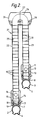
- FIG. 1 A schematic sectional view of a conventional steam generator unit for a liquid retal cooled fast breeder reactor (LMCFBR) is shown in Figure 1 of the accompanying drawings.
- the unit comprises a straight elongate vertical shell 1 extending between a feed water inlet header 2 and a steam outlet header 3.
- the header 2 has a water inlet nozzle 4 and the header 3 has a steam outlet nozzle 5.
- a bundle 6 of vertical tubes conducts water and steam from the header 2 to the header 3. For the sake of clarity, only the outline of the bundle is shown as two chain-dotted lines.
- the tubes extend between a tubeplate 7 in the header 2 and a tubeplate 8 in the header 3, and are welded at their respective ends to the tubeplates.
- the bundle 6 of tubes is enclosed within a cylindrical shroud 9, and is supported by horizontal grid plates 10, spaced apart over the length of the shroud.
- Liquid sodium is fed into the shell 1 via an inlet nozzle 11, passes through an annular chamber 12 and a distribution grid 13 and enters the interior of the shroud 9.
- the sodium flows downwards within the shroud in thermal contact with the tubes, passing through the grid plates 10.
- the major part of the sodium flow leaves the shroud via apertures in an outlet section 14, enters an annular chamber 15 and then leaves the shell 1 via an outlet nozzle 16.
- the remainder of the liquid sodium flow is conducted downwards through grids 17, 18, 19 to act as a thermal barrier to protect the tubeplate 7.
- the shell may include a bellows device 20 to allow for differential expansion of the shell and the tubes.
- This conventional type of steam generator unit suffers from a number of disadvantages. Firstly, the straight shell and tube configuration requires the bellows device to give tolerance to tube-shell temperature differences. Secondly, the configuration has poor tolerance to temperature differences between the tubes. Thirdly, it is very long (for example approximately 37 metres), and this gives rise to a number of problems. Thus, the building in which it is housed must be very high, manufacture, transport and erection of the unit are difficult and, more especially, the tubes must be in continuous lengths, because sub-sodium tube to tube welds are considered undesirable. Furthermore, the plant required to draw tubes of the full heat exchanger length and to heat treat them would involve very considerable capital expenditure.
- a heat exchanger of the type comprising a group of substantially parallel elongate tubes for conducting a flow of a first material, and an elongate outer shell containing said tubes and arranged to receive a flow of a second material around the tubes to enable exchange of heat between said first and second materials; wherein said outer shell comprises first and second substantially vertical elongate shell portions and an upper chamber interconnecting the shell portions; and wherein each tube comprises first and second tube portions each comprising a substantially vertical limb and an upper portion, the upper portions of the first and second tube portions being joined to form an inverted U-shaped region within the chamber, the vertical limbs being contained in said first and second shell portions, respectively; and wherein, in use of the heat exchanger, said second material is maintained at a level within the chamber, which level is below the points of joining of the upper tube portions.
- a shell 21 comprises two parallel side-by-side elongate sections 22 and 23 interconnected by a chamber 24 to which the sections are sealed.
- the steam outlet header 3 is now at the lower end of the shell section 23.
- the sodium inlet nozzle 11, the annular chamber 12 and the distribution grid 13 are now adjacent the lower end of the shell section 3.
- the sodium inlet and outlet nozzles 11, 16 are now preferably moved round their respective chambers by 90°, so that they extend perpendicular to the plane of the axes of the two shell sections. This allows for more convenient installation.
- Each tube in a bundle 25 now comprises two limbs, one contained in each of the shell sections, the limbs being interconnected at their upper ends by an inverted U-shaped tube region 26.
- the region 26 is preferably formed by bending the upper end of each tube limb through 90° and butt welding the ends of each two associated limbs together so that in the assembled tube bundle the welds all lie substantially in a plane 27.
- the liquid sodium is maintained at a level 28 in the chamber 24, which level lies below the lowest point of the tube welds. Hence, the welds are not submerged in the sodium.
- the space above the sodium level 28 is filled with a blanket gas, such as argon. This gas can be used for detecting leakage from the tubes at the weld area.
- the bent tube sections are above the sodium level 28 and are therefore substantially free from significant dynamic excitation. It may therefore not be necessary to provide grid plates for supporting the tubes over those sections.
- the fact that the tube bends are unsupported, and therefore relatively flexible, means that there is large tolerance to differential tube/tube and tube/shell thermal expansion.
- the shell sections 22, 23 are shown as being of unequal lengths. However, each can be of any desired length. One section might be sufficiently long to carry out economising and evaporation duties, and the other to carry out the superheating duty.
- the "folded" configuration of the steam generator unit according to the invention provides a number of very important advantages over the conventional straight configuration.
- the overall height of the unit can be much shorter, for example 24 metres as compared with a conventional 37 metre unit.
- the building to house the unit can be correspondingly lower.
- aseismic design is eased by the reduced height, and sodium feed and steam pipework can be shorter. The cost of the installation is therefore reduced.
- the configuration permits “upward boiling”, which is advantageous because it tends to be hydrodynamically stable at low loads and at start up conditions.
- the tube lengths which must be manufactured and transported are much shorter.
- the shell and the shroud are each formed in relatively short sections which are readily joined to the chamber 24, again reducing the cost and difficulty of manufacture and the difficulty of transportation.
- the butt welding of tubes would not be acceptable, because the welds would lie within the liquid sodium.
- the welding of tube sections is satisfactory because the welds lie above the sodium level and within a gas space. The gas can be used for tube leak detection.
- the greater flexibility provided by the inverted U-bends gives greater tolerance to differential thermal expansions, and also to dimensional variations during assembly and during the welding of the tubes to the tubeplates.
- heat exchanger is a steam generator unit for an LMCFBR, it will be apparent that the invention may be applied to heat exchangers for use in other applications.
Landscapes
- Engineering & Computer Science (AREA)
- Physics & Mathematics (AREA)
- Thermal Sciences (AREA)
- Mechanical Engineering (AREA)
- General Engineering & Computer Science (AREA)
- High Energy & Nuclear Physics (AREA)
- Life Sciences & Earth Sciences (AREA)
- Sustainable Development (AREA)
- Sustainable Energy (AREA)
- Heat-Exchange Devices With Radiators And Conduit Assemblies (AREA)
Applications Claiming Priority (2)
| Application Number | Priority Date | Filing Date | Title |
|---|---|---|---|
| GB898911741A GB8911741D0 (en) | 1989-05-22 | 1989-05-22 | Heat exchangers |
| GB8911741 | 1989-05-22 |
Publications (1)
| Publication Number | Publication Date |
|---|---|
| EP0399722A1 true EP0399722A1 (de) | 1990-11-28 |
Family
ID=10657155
Family Applications (1)
| Application Number | Title | Priority Date | Filing Date |
|---|---|---|---|
| EP90305267A Withdrawn EP0399722A1 (de) | 1989-05-22 | 1990-05-16 | Wärmeaustauscher |
Country Status (4)
| Country | Link |
|---|---|
| US (1) | US5101893A (de) |
| EP (1) | EP0399722A1 (de) |
| JP (1) | JPH0336401A (de) |
| GB (1) | GB8911741D0 (de) |
Cited By (2)
| Publication number | Priority date | Publication date | Assignee | Title |
|---|---|---|---|---|
| RU2153709C2 (ru) * | 1998-09-28 | 2000-07-27 | Опытное конструкторское бюро машиностроения | Парогенератор для интегральных ядерных реакторов |
| FR2805333A1 (fr) * | 2000-02-22 | 2001-08-24 | Gen Electric | Generateur de vapeur integre pour reacteur a metal liquide |
Citations (3)
| Publication number | Priority date | Publication date | Assignee | Title |
|---|---|---|---|---|
| FR1197675A (fr) * | 1957-09-18 | 1959-12-02 | Babcock & Wilcox France | Groupe évaporatoire |
| FR2128197A1 (en) * | 1971-03-11 | 1972-10-20 | Stein Industrie | Tube bundle support - comprising resilient honeycomb frame for fast-neutron nuclear reactor steam generators |
| EP0094732A2 (de) * | 1982-05-19 | 1983-11-23 | Westinghouse Electric Corporation | Dampferzeuger für flüssigmetallgekühlten schnellen Brutreaktor |
Family Cites Families (10)
| Publication number | Priority date | Publication date | Assignee | Title |
|---|---|---|---|---|
| US2520755A (en) * | 1948-09-13 | 1950-08-29 | Brown Fintube Co | Multiple tube heat exchanger |
| GB895912A (en) * | 1960-03-07 | 1962-05-09 | Brown Fintube Co | Heat exchanger |
| US3155404A (en) * | 1963-12-17 | 1964-11-03 | Brown Fintube Co | Union for connecting conduits |
| GB1088115A (en) * | 1965-03-22 | 1967-10-25 | C A Parsons & Company | Improvements in and relating to tubular heat exchangers |
| US3263423A (en) * | 1965-06-10 | 1966-08-02 | Foster Wheeler Corp | Supercharged steam generator for powerplant |
| GB1331134A (en) * | 1970-07-31 | 1973-09-26 | Westinghouse Electric Corp | Heat exchanger having a plurality of modular tube bundles |
| DE2244207C3 (de) * | 1972-09-08 | 1978-07-13 | Siemens Ag, 1000 Berlin Und 8000 Muenchen | Dampferzeuger |
| DE2256633C3 (de) * | 1972-11-17 | 1975-10-30 | Siemens Ag, 1000 Berlin Und 8000 Muenchen | Dampferzeuger |
| DE2558127C2 (de) * | 1975-12-23 | 1978-01-19 | Kraftwerk Union AG, 4330 Mülheim | Dampferzeuger mit U-förmig gebogenen Wärmetauscherrohren |
| US4230527A (en) * | 1977-04-29 | 1980-10-28 | Alexander Cella | Steam generator for use in nuclear power plants |
-
1989
- 1989-05-22 GB GB898911741A patent/GB8911741D0/en active Pending
-
1990
- 1990-05-16 EP EP90305267A patent/EP0399722A1/de not_active Withdrawn
- 1990-05-16 US US07/524,174 patent/US5101893A/en not_active Expired - Fee Related
- 1990-05-22 JP JP2132404A patent/JPH0336401A/ja active Pending
Patent Citations (3)
| Publication number | Priority date | Publication date | Assignee | Title |
|---|---|---|---|---|
| FR1197675A (fr) * | 1957-09-18 | 1959-12-02 | Babcock & Wilcox France | Groupe évaporatoire |
| FR2128197A1 (en) * | 1971-03-11 | 1972-10-20 | Stein Industrie | Tube bundle support - comprising resilient honeycomb frame for fast-neutron nuclear reactor steam generators |
| EP0094732A2 (de) * | 1982-05-19 | 1983-11-23 | Westinghouse Electric Corporation | Dampferzeuger für flüssigmetallgekühlten schnellen Brutreaktor |
Cited By (2)
| Publication number | Priority date | Publication date | Assignee | Title |
|---|---|---|---|---|
| RU2153709C2 (ru) * | 1998-09-28 | 2000-07-27 | Опытное конструкторское бюро машиностроения | Парогенератор для интегральных ядерных реакторов |
| FR2805333A1 (fr) * | 2000-02-22 | 2001-08-24 | Gen Electric | Generateur de vapeur integre pour reacteur a metal liquide |
Also Published As
| Publication number | Publication date |
|---|---|
| US5101893A (en) | 1992-04-07 |
| JPH0336401A (ja) | 1991-02-18 |
| GB8911741D0 (en) | 1989-07-05 |
Similar Documents
| Publication | Publication Date | Title |
|---|---|---|
| EP2338007B1 (de) | Werksmontierter wärmetauscher für einen solarempfänger | |
| US4384550A (en) | Thermal receiver | |
| RU2583321C1 (ru) | Парогенератор с горизонтальным пучком теплообменных труб и способ его сборки | |
| US4084546A (en) | Heat exchanger | |
| EP0572265B1 (de) | Wärmetauscherelement für einen Abhitzedampferzeuger | |
| US4245588A (en) | Vapor generating system having a division wall penetrating a furnace boundary wall formed in part by angularly extending fluid flow tubes | |
| US3854528A (en) | Heat-exchanger module | |
| EP2245406B1 (de) | Wärmetauscher | |
| US3245464A (en) | Liquid metal heated vapor generator | |
| JPS60155801A (ja) | 蒸気発生器 | |
| US3298360A (en) | Pressure-fired once-through boiler | |
| US5101893A (en) | Heat exchangers | |
| US4120348A (en) | Heat exchanger having a plurality of modules connected in parallel | |
| US6526115B2 (en) | Supercritical-pressure water cooled reactor and power generation plant | |
| US4182413A (en) | Radial flow heat exchanger | |
| US4073267A (en) | Vapor generator | |
| US3651789A (en) | Steam generator | |
| US3358650A (en) | Water cooled furnace joint for mixing header arrangement | |
| US4296713A (en) | Vapor generator | |
| US3280799A (en) | Fluid heater support arrangement | |
| US4136644A (en) | Tube heat exchanger with heating tubes | |
| JP7515479B2 (ja) | 鉛冷却材を備えた高速中性子炉用の逆蒸気発生器 | |
| US3307524A (en) | Fluid heater support | |
| US3354869A (en) | Heat exchangers | |
| WO1990006482A1 (en) | Heat exchanger |
Legal Events
| Date | Code | Title | Description |
|---|---|---|---|
| PUAI | Public reference made under article 153(3) epc to a published international application that has entered the european phase |
Free format text: ORIGINAL CODE: 0009012 |
|
| 17P | Request for examination filed |
Effective date: 19900926 |
|
| AK | Designated contracting states |
Kind code of ref document: A1 Designated state(s): DE FR GB IT NL |
|
| 17Q | First examination report despatched |
Effective date: 19910620 |
|
| STAA | Information on the status of an ep patent application or granted ep patent |
Free format text: STATUS: THE APPLICATION IS DEEMED TO BE WITHDRAWN |
|
| 18D | Application deemed to be withdrawn |
Effective date: 19911231 |