EP0094732A2 - Dampferzeuger für flüssigmetallgekühlten schnellen Brutreaktor - Google Patents
Dampferzeuger für flüssigmetallgekühlten schnellen Brutreaktor Download PDFInfo
- Publication number
- EP0094732A2 EP0094732A2 EP83300260A EP83300260A EP0094732A2 EP 0094732 A2 EP0094732 A2 EP 0094732A2 EP 83300260 A EP83300260 A EP 83300260A EP 83300260 A EP83300260 A EP 83300260A EP 0094732 A2 EP0094732 A2 EP 0094732A2
- Authority
- EP
- European Patent Office
- Prior art keywords
- section
- shroud
- bent
- tubes
- tube
- Prior art date
- Legal status (The legal status is an assumption and is not a legal conclusion. Google has not performed a legal analysis and makes no representation as to the accuracy of the status listed.)
- Withdrawn
Links
Images


Classifications
-
- F—MECHANICAL ENGINEERING; LIGHTING; HEATING; WEAPONS; BLASTING
- F22—STEAM GENERATION
- F22B—METHODS OF STEAM GENERATION; STEAM BOILERS
- F22B37/00—Component parts or details of steam boilers
- F22B37/02—Component parts or details of steam boilers applicable to more than one kind or type of steam boiler
- F22B37/10—Water tubes; Accessories therefor
- F22B37/20—Supporting arrangements, e.g. for securing water-tube sets
- F22B37/205—Supporting and spacing arrangements for tubes of a tube bundle
-
- F—MECHANICAL ENGINEERING; LIGHTING; HEATING; WEAPONS; BLASTING
- F22—STEAM GENERATION
- F22B—METHODS OF STEAM GENERATION; STEAM BOILERS
- F22B1/00—Methods of steam generation characterised by form of heating method
- F22B1/02—Methods of steam generation characterised by form of heating method by exploitation of the heat content of hot heat carriers
- F22B1/06—Methods of steam generation characterised by form of heating method by exploitation of the heat content of hot heat carriers the heat carrier being molten; Use of molten metal, e.g. zinc, as heat transfer medium
- F22B1/063—Methods of steam generation characterised by form of heating method by exploitation of the heat content of hot heat carriers the heat carrier being molten; Use of molten metal, e.g. zinc, as heat transfer medium for metal cooled nuclear reactors
Definitions
- This invention relates to J-shaped steam generators for liquid metal fast breeder reactors.
- the steam generators used to transfer energy from a liquid coolant (usually liquid sodium) to water are key components in the successful operation of a Liquid Metal Fast Breeder Reactor (LMFBR) power plant.
- LMFBR Liquid Metal Fast Breeder Reactor
- a prototype J-shaped steam generator has been designed for use in a LMFBR. Tests, however, have revealed problems with this design especially problems caused by expansion of the tubes in the housing.
- the present invention resides in a steam generator for a liquid metal fast breeder reactor comprising a J-shaped tube bundle disposed between tube sheets mounted- in a J-shaped housing surrounding the tube bundle, said tube bundle and housing having major vertical sections with a horizontal tube sheet at one end thereof and a minor bent-over section projecting from the vertical section at its other end and having a tube sheet mounted at its free end with the tubes of the tube bundle being bent by about 90° at the juncture of said vertical and bent-over section so as to permit expansion of said tubes relative to said housing, said vertical major section being of substantially greater length than said minor section, characterized .in that said tube bundle is supported in said vertical housing section by at least one cruciform support structure permitting radial expansion of said tube bundle relative to said housing section but retaining said tube bundle centrally within said housing section, and that the tubes of said minor section are so supported as to permit up and downward movement of said tubes relative to said bent-over housing section.
- the energy generated by the reactor is to be removed from the primary system by three heat removal systems each comprising three steam generators. Two of the steam generators in each system are designated evaporators and one is designated a superheater. All steam generators are almost identical in design, and any evaporator is interchangeable with any superheater by removing or installing an individual water flow throttle used at the inlet of each evaporator tube to ensure boiling flow stability in the evaporator.
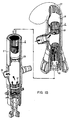
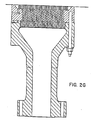
- evaporators and superheaters are installed in a vertical position as shown in Figs. 1A and 1B and are shell and tube heat exchangers with fixed tube sheets and with a bend (usually 90°) in the shell and tube bundle ("J-tube" configuration) to provide for differential thermal expansion between the tubes and the shell.
- Figures 1A and 1B depict a bend of 180°.
- Sodium flow (solid arrows), is vertically downward, parallel with the tubes on the shell side from the sodium inlet nozzle 1 near the top of the active straight section countercurrent to the steam/water flow upward inside tubes 2.
- the material of construction for shell 3, tube sheets, tubes 2 and other elements of the evaporator and superheater is 2-1/4 CR-l-MO.
- tubes 2 require lateral support for seismic events, shipping and proper tube-to-tube spacing. This results in the problem of how to properly support tubes 2 with relatively long spans.
- lateral support in the bend section is provided by support bars between adjacent rows of tubes (not shown), used to provide lateral support while allowing free movement therethrough. It has been determined that one support at the 90° location will not provide proper tube 2 spacing. Prior attempts with additional similar supports at 30° and 60° resulted in failure and buckling of the tubes 2 due to differential expansion between tubes 2 and subsequent jamming in the support bars.
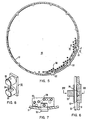
- the array of tubes 2 is to be laterally supported by a plurality, preferably 4 per 90° of bend, of support grids 5 each of which has ribs 6 which provide lateral support to only every other row of tubes 2.
- a given row of tubes 2 is supported laterally by every other support plate.
- This design provides for tube support and spacing, and allows thermal expansion into gaps 9.
- the array of tubes 2 within the steam generator is surrounded by a container called the shroud.
- this shroud In the upper part of the steam generator in the vicinity of the bend this shroud is termed the elbow shroud 14.
- a gap must exist between the inner row of tubes and the elbow shroud 14 to prevent contact of the inner row of tubes with elbow shroud 14 during thermal expansion. This gap tends to increase the overall diameter of the steam generator.
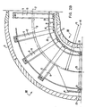
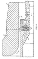
- the centerline 18 of the elbow shroud 14 is not identical with the shell centerline 17.
- Fig. 2B the center of the arc of the elbow shroud centerline 18, point 15, is not identical to the center 16 of the arc of tubes 2 and shell 3, point 16. These two points 15 and 16 are separated by approximately 2.5 inches.
- Tubes 2 remain concentric with respect to shell 3 but an eccentricity exists between elbow shroud 14 and tubes 2. This eccentricity results in a gain of between 2.5 to 6.5 cm. in the width of gap 19 between the elbow shroud and the nearest row 20 of tubes 2.
- the variation in the size of gap 19, shown in Fig. 2B roughly corresponds to the variation in the deflection in tubes 2 caused by thermal contraction.
- the size of the gap 19 can therefore be minimized rather than maximized to be appropriate to the size of the worst case tube contraction.
- a_ greater AT may be accommodated by the steam generator without the inside tube thermally contracting and contacting elbow shroud 14. This increases the size of the thermal transients that can be accommodated by the steam generator of a given diameter.
- elbow shroud 14 is installed after tubes 2 are installed.
- the mechanical joint between elbow. shroud 14 and inlet thermal liner 21 has been required because of the need to accomplish this joint after the installation of tubes 2 at which time a welding operation would be extremely difficult.
- elbow shroud 14 is left open on the top side (see openings 22 in Fig. 1B) to permit tubing of the unit with elbow shroud 14 and thermal liner 21 in place.
- Tube support top rings (not shown in the drawings) are welded in place after tubing.
- the thermal liner 21 material is to be 316 stainless steel instead of 2-1/4 CR-IMO to facilitate welding.
- the connection between elbow shroud 14 and thermal liner 21 is now to be a weldment 23 as opposed to a bolted design and therefore these components can be considered to be an integral unit.
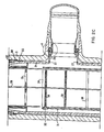
- a problem related to properly supporting tubes 2 in the elbow region is the potential for damage from flow induced vibration of the flexible spans of tubes 2 in the elbow region because of the low natural frequency of the tubes and potentially large amplitudes of the vibrations. Vibration dampers could be used but these are difficult to design and still permit free tube 2 motion during thermal expansion. Vibration of tube:: 2 in the bend area is considered to come from sodium flow entering the bundle inlet 24. Bundle inlet 24 is the region at the top of the shroud.
- This invention greatly reduces vibration in the bend area of tubes 2 by lowering the position of bundle inlet 24 with respect to inlet nozzle 1 thus separating the bent portion of tubes 2 in the elbow region and the vibration excitation- forces.
- the two existing spacer plates 25 (see Figs. 2B and 2C) have been separated an additional amount over prior art effectively isolating the tubes from the excitation forces. Frequencies that can bypass these two separated plates 25 do not occur in the steam generator. These features have been demonstrated by calculations.
- lowering the bundle 24 inlet minimizes thermal fatigue and transient problems in the elbow region due to inlet flow penetration into the elbow. This is considered to be a significant improvement.
- the prior state of the art utilizes a mechanical connection between the inlet thermal liner 21 and a nozzle liner 26.
- This invention utilizes a weld connection 27 between inlet thermal liner 21 and a labyrinth disc seal to limit flow through the nozzle annulus. The direction of flow is controlled during steady state operation by having a lower static pressure at a step in the seal which forces the flow out from discs 28.
- the weld between the inlet thermal liner 21 and nozzle seal is a stainless steel weld. This is important because the weld can be accomplished without preheat and post-weld heat treatment which would be required if a 2-1/4 chromium-IMO liner were used.
- the seal discs 28 provide a convenient place for interfacing between the stainless steel liner 21 and the 2-1/4 chromium-lMO inlet nozzle.
- the seal itself is considered to be a novel design having a general shape of an annular disc 28 with an inner edge expanded to have a circular cross section and an outer edge expanded to have a circular cross section.
- a cross section of the seal appears as two balls connected by a straight section, as in Fig. 4.
- One of the two "balls" will always be in contact with a sealing surface whatever direction AT expansion occurs.
- the support of the thermal liner 21 and elbow shroud 14 has been by bolted connections.
- the support of the integral thermal liner 21 and elbow shroud 14 is accomplished with a radial key arrangement.
- These keys 57 are Inconel 718 and are mechanically attached to the stainless steel thermal liner 21.
- the radial keys 57 prevent lateral motion or vibration.
- the keys have integral pads which support the thermal liner and elbow shroud on the inlet header.
- These keys mate with a separate set of keyways machined into a ring 58 that is fitted into the inside diameter of the inlet header.
- the separate ring prevents placing stress concentrations in the shell and facilitates angular adjustment of the keyway orientation.
- the keys and integral pads permit sliding during thermal differential expansion between the stainless steel thermal liner and 2-1/4 chromium-IMO shell. Uploads on the assembly are reacted by a shear ring 59 which is locked in place by pins 60 that facilitate installation and removal.
- the keys 57 which may have a cruciform cross section are an appropriate location to accomplish the interface between the stainless steel thermal liner and the 2-1/4 chromium-IMO shell.
- spacer plates 30 are used to provide support and proper spacing for the array of tubes 2. These spacer plates 30 according to the prior art are attached to a shroud 21 by bolts. According to this invention, a unique spacer retainer 32 will be used to support the spacer plates 30 and to react vertical loads. This method allows the spacer plate 30 to float freely within the clearance between the shroud 31 inner diameter and the spacer plate 30 outer diameter. This floating feature-is very important because it provides flexibility to the tube array which relieves some of the tube 2 side loads by permitting small side deflections. This ultimately reduces the axial frictional loads and potentially tube 2 buckling, jamming and subsequent failure.
- a plurality of tube spacer retainers 32 are locked to the shroud 31 by tube spacer retainer bars 33 located at intervals around the parameter of shroud 31.
- Spacer plates 30 are inserted into a gap 34 between two lugs 35 on the tube space retainer 32.
- a small gap 36 exists between the outer diameter of the spacer plate 30 and the flat surface of the tube space retainer 32 (see Fig. 6). This gap 36 is the interval within which the spacer plate 30 can float freely.
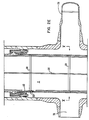
- the bundle outlet 37 is to be lowered with respect to the sodium outlet 38.
- the bundle outlet 37 is approximately 18 inches lower than in the prior art.
- the cylindrical shroud 31 has generally been supported at the top by means of bolts which attach to a flange (not shown) on the side of the shell. It is desired to install shroud 31 from the bottom to facilitate welding operations on the thermal liner 21 and on the nozzle liner 26. Installation of shroud 31 from the bottom eliminates the use of a flange unless the bolts can stay under tension indefinitely which is undesirable. Consequently, a new method for supporting shroud 31 has been developed by which means shroud 31 is to be supported generally at a bottom position 39 with a vibration dampening arrangement at a top location 40. Figs. 9, 10A and 11 show the support means of shroud 31. Nut plate 40 is attached to shroud 31.
- Shroud 31 is inserted into shell 3 from the bottom and inserted sufficiently that nut plate 40 slides past lugs 41 which are an integral part of shell 3 and then shroud 31 and nut plate 40 are rotated.
- Main support ring 42 is also inserted from the bottom, sliding past lugs 41 and then rotated.
- Lower support ring 43 forms a key with lugs 41 on shell 3.
- Main support ring 42 forms a key with shroud 31.
- the main support ring 42 and the lower support ring 43 meet on a diameter (point 44) so translation with respect to each other is impossible. The assembled support therefore allows radial expansion due to temperature changes while providing vertical support for the shroud and angular misalignment compensation.
- the purpose of the bolt 45 is to provide support for shipping and during accidents.
- the nut plate 40, the main support ring 42, the lower support ring 43 and the bolt installation ring 46 are all composed of type 718 nickel alloy.
- the shroud and the shell are 2-1/4 chromium-1MO.
- Figs. 1, 2D, and 12 show the vibration damper 47.
- the vibration damper 47 - is used to dampen vibrations of thermal liner 21 and shroud 31.
- One vibration damper 47 does both.
- the vibration damper 47 is designed to dampen vibrations as induced by flow. Seismic vibrations are accommodated by translations of thermal liner 21 and shroud 31 causing bumping contact on provided bumping surfaces of shell 3. This type of solution is not available for flow induced vibration due to the potential for wear.
- a plurality of leaf springs 48 integral to a ring 49 which is itself attached to thermal liner 21 bear - on shell 3 and are used to dampen out vibrations in the bottom of thermal liner 21.
- each tuning fork 50 is compressed when it enters a notch 51 in a top ring 52 on the thermal liner 31.
- Both the leaf springs and the tuning fork configurations dampen out or eliminate vibrations by frictional force generated by movements within the notch or against the shell associated with vibrational translations.
- Cantilevered beams or arms made of nickel alloy 718 preserve flexibility of the internals to permit axial expansion without jamming in notch 51.
Landscapes
- Engineering & Computer Science (AREA)
- Physics & Mathematics (AREA)
- Thermal Sciences (AREA)
- Mechanical Engineering (AREA)
- General Engineering & Computer Science (AREA)
- Life Sciences & Earth Sciences (AREA)
- High Energy & Nuclear Physics (AREA)
- Sustainable Development (AREA)
- Sustainable Energy (AREA)
- Heat-Exchange Devices With Radiators And Conduit Assemblies (AREA)
- Structure Of Emergency Protection For Nuclear Reactors (AREA)
- Manufacture And Refinement Of Metals (AREA)
- Monitoring And Testing Of Nuclear Reactors (AREA)
Applications Claiming Priority (2)
| Application Number | Priority Date | Filing Date | Title |
|---|---|---|---|
| US379812 | 1982-05-19 | ||
| US06/379,812 US4517927A (en) | 1982-05-19 | 1982-05-19 | Steam generator for liquid metal fast breeder reactor |
Publications (2)
| Publication Number | Publication Date |
|---|---|
| EP0094732A2 true EP0094732A2 (de) | 1983-11-23 |
| EP0094732A3 EP0094732A3 (de) | 1984-12-05 |
Family
ID=23498800
Family Applications (1)
| Application Number | Title | Priority Date | Filing Date |
|---|---|---|---|
| EP83300260A Withdrawn EP0094732A3 (de) | 1982-05-19 | 1983-01-19 | Dampferzeuger für flüssigmetallgekühlten schnellen Brutreaktor |
Country Status (3)
| Country | Link |
|---|---|
| US (1) | US4517927A (de) |
| EP (1) | EP0094732A3 (de) |
| JP (1) | JPS58200901A (de) |
Cited By (2)
| Publication number | Priority date | Publication date | Assignee | Title |
|---|---|---|---|---|
| GB2206958A (en) * | 1987-07-13 | 1989-01-18 | Nat Nuclear Corp Ltd | Steam generators |
| EP0399722A1 (de) * | 1989-05-22 | 1990-11-28 | Nnc Limited | Wärmeaustauscher |
Families Citing this family (2)
| Publication number | Priority date | Publication date | Assignee | Title |
|---|---|---|---|---|
| US4688628A (en) * | 1985-12-06 | 1987-08-25 | Rockwell International Corporation | Steam generator support system |
| CN114151781B (zh) * | 2021-12-07 | 2023-08-25 | 中船九江锅炉有限公司 | 一种防止水位纵横摇晃的船用锅炉 |
Family Cites Families (9)
| Publication number | Priority date | Publication date | Assignee | Title |
|---|---|---|---|---|
| US1777356A (en) * | 1927-05-17 | 1930-10-07 | Empire Gas And Fuel Company | Heat-interchange apparatus |
| US3007679A (en) * | 1960-06-22 | 1961-11-07 | Westinghouse Electric Corp | Anti-vibration structure for heat exchanger tubes |
| US3212567A (en) * | 1962-05-08 | 1965-10-19 | Combustion Eng | Anti-vibration support means |
| FR2128197A1 (en) * | 1971-03-11 | 1972-10-20 | Stein Industrie | Tube bundle support - comprising resilient honeycomb frame for fast-neutron nuclear reactor steam generators |
| US3807365A (en) * | 1972-07-24 | 1974-04-30 | Westinghouse Electric Corp | U-tube steam generator with segment superheater |
| DE2337791C2 (de) * | 1973-07-25 | 1978-07-13 | Siemens Ag, 1000 Berlin Und 8000 Muenchen | Dampferzeuger |
| US4088182A (en) * | 1974-05-29 | 1978-05-09 | The United States Of America As Represented By The United States Department Of Energy | Temperature control system for a J-module heat exchanger |
| US4114684A (en) * | 1977-04-11 | 1978-09-19 | General Electric Company | Tube support system for heat exchanger |
| FR2404799A1 (fr) * | 1977-09-28 | 1979-04-27 | Commissariat Energie Atomique | Generateur de vapeur pour centrale a eau pressurisee |
-
1982
- 1982-05-19 US US06/379,812 patent/US4517927A/en not_active Expired - Fee Related
-
1983
- 1983-01-19 EP EP83300260A patent/EP0094732A3/de not_active Withdrawn
- 1983-01-19 JP JP58007992A patent/JPS58200901A/ja active Pending
Cited By (4)
| Publication number | Priority date | Publication date | Assignee | Title |
|---|---|---|---|---|
| GB2206958A (en) * | 1987-07-13 | 1989-01-18 | Nat Nuclear Corp Ltd | Steam generators |
| GB2206958B (en) * | 1987-07-13 | 1991-09-18 | Nat Nuclear Corp Ltd | Heat exchanger support structures |
| EP0399722A1 (de) * | 1989-05-22 | 1990-11-28 | Nnc Limited | Wärmeaustauscher |
| US5101893A (en) * | 1989-05-22 | 1992-04-07 | Nnc Limited | Heat exchangers |
Also Published As
| Publication number | Publication date |
|---|---|
| EP0094732A3 (de) | 1984-12-05 |
| JPS58200901A (ja) | 1983-11-22 |
| US4517927A (en) | 1985-05-21 |
Similar Documents
| Publication | Publication Date | Title |
|---|---|---|
| JP6453343B2 (ja) | 蒸気発生器管支持体 | |
| US5502754A (en) | Lateral restraint for core plate of boiling water reactor | |
| US11448393B2 (en) | Tube support system for nuclear steam generators | |
| EP0725222A2 (de) | Federrastmechanismus | |
| US4653576A (en) | Expandable antivibration bar for a steam generator | |
| US6997141B2 (en) | Anti-vibration support for steam generator heat transfer tubes and method for making same | |
| US4690206A (en) | Nuclear steam generator wrapper barrel/tube support plate connection assembly and radial tuning method for assembling same | |
| US4720840A (en) | Compliant antivibration bar for a steam generator | |
| US9347662B2 (en) | Tube support system for nuclear steam generators | |
| US4517927A (en) | Steam generator for liquid metal fast breeder reactor | |
| US5621778A (en) | Shroud restraint stabilizer | |
| US5737379A (en) | Reactor core shroud repair using thermally tensioned ring to apply compression across shroud vertical seam welds | |
| US4718479A (en) | Antivibration bar installation apparatus | |
| JPH0718522B2 (ja) | 加圧水型原子炉用蒸気発生器 | |
| CA2673904C (en) | Tube support system for nuclear steam generators | |
| JPS60179589A (ja) | 直径に対して肉厚が小さいパイプの支持装置 | |
| US4296713A (en) | Vapor generator | |
| Glasgow et al. | Technical advances in mechanical design of AGR boilers | |
| JPH0544999B2 (de) | ||
| GB2193299A (en) | Compliant anti-vibration bar for a steam generator |
Legal Events
| Date | Code | Title | Description |
|---|---|---|---|
| PUAI | Public reference made under article 153(3) epc to a published international application that has entered the european phase |
Free format text: ORIGINAL CODE: 0009012 |
|
| AK | Designated contracting states |
Designated state(s): BE DE FR GB IT |
|
| PUAL | Search report despatched |
Free format text: ORIGINAL CODE: 0009013 |
|
| AK | Designated contracting states |
Designated state(s): BE DE FR GB IT |
|
| STAA | Information on the status of an ep patent application or granted ep patent |
Free format text: STATUS: THE APPLICATION IS DEEMED TO BE WITHDRAWN |
|
| 18D | Application deemed to be withdrawn |
Effective date: 19850731 |
|
| RIN1 | Information on inventor provided before grant (corrected) |
Inventor name: WINEMAN, ARTHUR LEROY Inventor name: ROBEY, ROBERT MCDOWELL Inventor name: GILLETT, JAMES EDWIN Inventor name: GARNER, DANIEL CLARK |