EP0399992A2 - Machine à souder pour grilles - Google Patents
Machine à souder pour grilles Download PDFInfo
- Publication number
- EP0399992A2 EP0399992A2 EP90890144A EP90890144A EP0399992A2 EP 0399992 A2 EP0399992 A2 EP 0399992A2 EP 90890144 A EP90890144 A EP 90890144A EP 90890144 A EP90890144 A EP 90890144A EP 0399992 A2 EP0399992 A2 EP 0399992A2
- Authority
- EP
- European Patent Office
- Prior art keywords
- welding
- welding machine
- lower electrode
- cylinder
- head
- Prior art date
- Legal status (The legal status is an assumption and is not a legal conclusion. Google has not performed a legal analysis and makes no representation as to the accuracy of the status listed.)
- Granted
Links
Images

Classifications
-
- B—PERFORMING OPERATIONS; TRANSPORTING
- B23—MACHINE TOOLS; METAL-WORKING NOT OTHERWISE PROVIDED FOR
- B23K—SOLDERING OR UNSOLDERING; WELDING; CLADDING OR PLATING BY SOLDERING OR WELDING; CUTTING BY APPLYING HEAT LOCALLY, e.g. FLAME CUTTING; WORKING BY LASER BEAM
- B23K11/00—Resistance welding; Severing by resistance heating
- B23K11/002—Resistance welding; Severing by resistance heating specially adapted for particular articles or work
- B23K11/008—Manufacturing of metallic grids or mats by spot welding
Definitions
- the invention relates to a welding machine working according to the electrical resistance method for producing grids, which consist of intersecting longitudinal and transverse wires welded at the crossing points, with busbars fixed to the frame on one side of a horizontal welding plane, connected to welding transformers, and with a plurality of juxtaposed ones Welding heads, which each have an upper electrode arranged above the welding plane, a lower electrode arranged below the welding plane, one of the electrodes being movable against the other, a connecting piece passing through the welding plane from the busbars to the electrode on the opposite side of the welding plane and one the movable one
- the welding heads by means of a transport member which can be selectively coupled transversely to the long wire pre-lubricant can be moved into certain positions.
- a welding machine in which a welding head consisting of a lower and an upper welding electrode and a welding transformer has a drive device for moving the welding head, whereas the other welding heads are designed without a drive and with one another and with the drive device Welding head are connected in the manner of a train.
- a welding head is suspended in each case when the position determined by the spacing of the wire in the grid to be produced is reached.
- a disadvantage of this welding machine is the fact that when changing the position, even fewer welding heads always have to be coupled and moved, and that the welding heads are also heavy and unwieldy due to the integrated welding transformers.
- AT-PS 292.427 is a more user-friendly one with regard to the positioning of the welding heads
- Welding machine in which a drive spindle extending over the entire width of the welding machine is provided as the drive device for moving the welding heads, with which the welding heads can be selectively coupled via coupling elements.
- a drive spindle extending over the entire width of the welding machine is provided as the drive device for moving the welding heads, with which the welding heads can be selectively coupled via coupling elements.
- the upper electrode of each welding head can be lowered onto the lower electrode and / or the electrodes can be mechanically coupled by a coupling element in order to shift the welding heads. Automatic positioning is not intended for this welding machine.
- each welding head slides on a rail arranged below the welding plane. Because of the contamination of these sliding surfaces occurring during lattice production, in particular due to abrasion, scale and welding spatter, problems arise when moving the welding heads, and there is also the risk of the welding heads tilting, which is further favored by the fact that the welding heads are supported far below their center of gravity .
- the object of the present invention is to provide a welding machine of the type specified in the introduction, which avoids the disadvantages of the prior art and allows a stable coupling of the lower and upper electrode holders of the welding head and a reliable adjustment thereof in a simple manner.
- the welding machine according to the invention is characterized in that the lower electrode can be docked to the upper electrode in the vertical direction by means of the pressure-actuated welding cylinder and a height-adjustable anvil supporting the welding cylinder, in that a lower electrode holder carrying the lower electrode is connected to the connecting piece, which in turn has an upper part electrode-supporting upper electrode holder is firmly connected, can be connected to form a mechanically rigid welding head, and that this rigid welding head can be detached from a frame-fixed upper beam of the welding machine, from the busbars and from the anvil, can be coupled to a positioning carriage, and can be coupled with this along one across the longitudinal wire
- the feed direction can be moved across the width of the welding machine, the welding head can also be supported in the area of its under
- each individual welding head can be separated from the fixtures of the welding machine, in particular from the lower contact surface of the welding cylinder on the anvil, and it is advantageously possible for the welding heads to be moved and positioned automatically without the risk of tilting and twisting, and after the positioning, a vertical placement of the welding heads on the contact surface on the anvil.
- the lower electrode holder can be mechanically connected to the connecting piece via at least one centering pin attached to the lower electrode holder and insertable into a centering recess on the connecting piece and a locking pin arranged in the connecting piece and horizontally insertable into the lower electrode holder.
- the welding head can be detached from the upper beam by means of a pressure-actuated clamping cylinder and a return spring which acts on the welding cylinder in the vertical direction and acts upon it in the vertical direction, and by lowering a height-adjustable and controllable roadway suspension that supports the roadway.
- the positioning carriage is preferably between one Parking position and a working position can be adjusted vertically and can be moved horizontally transversely to the longitudinal wire feed direction on running rails which are arranged on a carriageway support extending across the width of the welding machine.
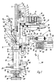
- FIGS. 1 and 2 each show a section through a welding machine according to the invention, wherein according to FIG. 1 a welding head of the welding machine in the displacement position and according to FIG Fig. 2 is shown in the welding position.
- a transverse wire Q is welded to longitudinal wires L of a longitudinal wire family.
- the welding heads K are arranged horizontally in a welding line depending on the required longitudinal wire division in the grid to be produced.
- the longitudinal wire coulter defines a horizontal welding plane E-E.
- Each welding head K has an upper, corresponding to the double arrow P2 vertically displaceable electrode holder 1, on the underside of which an upper electrode 2 is inserted.
- the upper electrode holder 1 has a trolley 3 with an impeller 4, via which the electrode holder runs parallel to the welding line on a roadway 5 which extends over the entire width of the welding machine.
- the road 5 is connected by means of a road suspension 6 according to the double arrow P3 vertically displaceable, with a fixed upper beam 7 attached to a machine frame, not shown, of the welding machine, the connection not being shown.
- the undercarriage 3, the impeller 4 and the track 5 of the adjacent welding head are arranged offset.
- the welding current is supplied to the upper electrode holder 1 by one of a total of four busbars 8, each of which is connected to transformers, not shown Sliding contact piece 9, a subsequent pantograph 10 and an upper current band 11 supplied.
- Each welding head also has a lower electrode holder 12, in the upper side of which a lower electrode 13 is inserted.
- the lower electrode holder 12 is connected to a plunger 14 of, for example, a hydraulically actuated welding cylinder 15, which is supported on an anvil 16, which extends across the machine width.
- the welding current for the lower electrode 13 is the lower electrode holder 12 analogous to the welding current for the upper electrode 2 from the busbar 8 selected accordingly by means of a slide 17 via a sliding contact piece 18, which is firmly connected to the sliding contact piece 9 of the current path for the upper electrode 2 by means of an insulating piece 19 a subsequent current collector 20, a flexible current band 21, a connecting piece 22 passing through the welding plane EE and a lower current band 23.
- the connecting piece 22 is mechanically screwed to the upper electrode holder 1, but is electrically separated from it by an insulating layer.
- the anvil 16 is raised by means of a lifting wedge gear 25 fastened to the base frame of the welding machine, which consists of a fixed wedge 26 and a sliding wedge 28 moved by means of a pull rod 27 (double arrow P5).
- the anvil 16 simultaneously raises the welding cylinder 15 and the lower electrode holder 12 upwards (double arrow P11 or P6). Then the welding cylinder 15 is connected via a hydraulic connection 29 Pressurized, and the plunger 14 with the attached lower electrode holder 12 extends upwards (double arrow Ppf) so far that the lower electrode 13 docks on the upper electrode 2. At least one centering pin 30 attached laterally to the lower electrode holder 12 snaps into a correspondingly shaped centering recess 31 on the connecting piece 22.
- a locking lever 32 By actuating a locking lever 32 corresponding to the double arrow P7 a locking pin 33 horizontally displaceable in the connecting piece 22 is pushed to the left (double arrow P8) so far that it reaches a corresponding centering hole in the lower electrode holder 12.
- the locking lever 32 can also be actuated automatically by means of a device, not shown, for example hydraulically operated.
- the welding head K is detached from the parts fixed to the frame of the welding machine, such as the upper beam 7, the busbars 8 and the anvil 16.
- a contact screw 35 is loosened, with which, in the welding position, the current collectors 20, the current collectors 10 and the sliding contact pieces 9, 18 are pressed firmly under the action of a hydraulically operated clamping device 34, for example, onto the busbars 8 selected by means of the slide 17, the Current collector 20 is electrically isolated from current collector 10 by an insulating layer 36.
- the head of the contact screw 35 is designed such that it can slide in a T-groove 38, which extends in a busbar support 37 parallel to the welding line over the entire width of the welding machine.
- a clamping piece 40 is loosened by a clamping cylinder 39, which can also be operated hydraulically, for example, so that the welding cylinder 15 can be released from a clamping strip 41 screwed to the anvil 16 and extending over the entire width of the welding machine.
- a feeder 42 for feeding the cross wire Q to the weld line, the in the welding position of the welding head by means of a locking bar 43 is connected to a feeder actuation 44 arranged in a fixed manner on the base frame of the welding machine, is released by pivoting the locking bar 43 to the left (double arrow P9), and falls in the direction of a feeder guide 45 attached to the upper electrode holder 1 the double arrow P10 down to a lowermost position.
- the working pressure in the welding cylinder 15 is switched off, whereupon the plunger 14, which hangs over the lower electrode holder 12 and over the locking pin 33 on the upper electrode holder 1, lifts the welding cylinder 15 upwards by a return spring, not shown, built into the welding cylinder 15 (double arrow P11 ) and thus releases the welding cylinder 15 from the anvil 16.
- the roadway suspension 6 is lowered by means not shown (double arrow P3), whereby the upper electrode holder suspended from the chassis 3 on the roadway support 6 lowers at the same time (double arrow P2) and the upper electrode holder 1 is insulated from one at the lower end of the upper beam 7 attached, preferably acute-angle centering bar 46 releases.
- a positioning carriage 47 is brought along a rack 48, which is only indicated schematically, into a working position 47 2 shown in FIG. 1 (double arrow P 1 2).
- a driver 50 is pushed to the left by means of a driver actuation 49 (double arrow P13) until it snaps into a correspondingly designed recess in a centering piece 51 which is advantageously attached near the welding plane E-E on the connecting piece 22 of the welding head.
- a roadway support 52 which is firmly connected to the base frame of the welding machine and extends transversely to the longitudinal wires L and over the entire width of the welding machine, there are two running rails 53 and another Rack 54 arranged.
- a drive pinion 55 of a stepping motor 56 which engages in the rack 54 and which, like the driver actuation 49, is fastened to a bracket 57 of the positioning carriage 47 and has a roller suspension 58 with a plurality of rollers 59 supported on the rails 53, the welding head K in the welding plane EE moved transversely to the line wire feed direction P1 (Fig. 2).
- the welding head K depends on the one hand on the wheels 4 on the road 5 of the road suspension 6 and on the other hand is supported below by a support wheel 60 on the side with a support track 41 'provided on the terminal block 41.
- the centering piece 51 which also serves to center the longitudinal wire feed tube 24, as far as possible in the welding plane EE, which practically represents the horizontal center line of the welding head K and is therefore close to the center of gravity thereof, a parallel displacement of the welding head is possible without great effort.
- the positioning carriage 47 After the welding head K has reached its welding position, which depends on the position of the longitudinal wire in the grid to be produced, the positioning carriage 47 is released by pulling the driver 50 out of the centering piece 51 (double arrow P 1 3) from the welding head K and can then take over the positioning of a further welding head . After completion of the positioning activity, the positioning carriage 47 moves back down to its parking position 47 1 (double arrow P 12).
- the clamping device 34 by actuating the clamping device 34, the upper electrode holder 1 or the connecting piece 22 via the current collectors 10, 20 and the sliding contact pieces 9, 18 are electrically connected to the busbars correspondingly selected by the slide 17.
- the clamping cylinder 39 By actuating the clamping cylinder 39, the clamping piece 40 and the welding cylinder 15 are pressed against the clamping strip 41 and thus fixed on the anvil 16.
- the working pressure in the welding cylinder 15 is now switched off, as a result of which the plunger 14 retracts through the return spring built into the welding cylinder 15 and takes the lower electrode holder 12 downward (double arrow P6).
- the anvil 16 is lowered into a lowermost position with the help of the lifting wedge gear 25 (double arrow P5) in order to facilitate the threading of the longitudinal wires L into the welding line.
- the feeder 42 is raised (double arrow P10) and by pivoting the locking bar 43 to the right (double arrow P9) on the feeder actuation 44 attached.
- the line wire feed tube 24 is advanced to the left (double arrow P4) and adjusted to the welding head in the welding position by means of a centering lug 63 which engages in the centering piece 51, which can also be carried out manually by means of a positioning device. All welding heads in the welding position are marked by means of a display 64.
- the anvil 16 After threading the longitudinal wires L, the anvil 16 is raised upwards with the help of the lifting wedge gear 25 (double arrow P5) until, depending on the total wire thickness of the longitudinal wire L and transverse wire Q to be welded, the lowest possible welding stroke of the lower electrode holder 12 in accordance with the double arrow P5 is set.
- the welding head works as follows: Via a cross wire feed 65, the cross wire Q is fed in the direction of arrow P14 and arrives at a cross wire flap 66 closing the feed channel of the cross wire feed 65.
- the line wire L is passed out of the line wire feed tube 24 a correspondingly formed recess in the connector 22 in the weld line between the upper electrode 2 and the lower electrode 13, advanced in the direction of arrow P1.
- the line wire L is held by guide elements, not shown, in the line wire feed tube 24 in a position which prevents the wire from not grinding on the lower electrode 13 when the line wires are fed in the direction of the arrow P 1.
- the cross wire flap 66 By pivoting the cross wire flap 66 down (double arrow P15), the feed channel for the cross wire Q is released and the cross wire Q falls down.
- the feeder actuation 44 By actuating the feeder actuation 44 downwards (double arrow P16), the cross wire is conveyed through the feeder 42 against cross wire stops, not shown, located in the welding line into the welding line and welded there with the longitudinal wires L after exposure to the welding pressure and switching on of the welding current.
- the fixed top electrode 2 serves as an abutment for building up the required welding pressure.
- a control device (not shown) is provided to control the individual devices for the automatic displacement and positioning of the welding heads, such as road suspension 7, welding cylinder 15, lifting wedge gear 25, locking lever 32, clamping device 34, clamping cylinder 39, positioning carriage 47, driver actuation 49 and stepping motor 56.
Landscapes
- Engineering & Computer Science (AREA)
- Manufacturing & Machinery (AREA)
- Mechanical Engineering (AREA)
- Resistance Welding (AREA)
- Wire Processing (AREA)
- Lining Or Joining Of Plastics Or The Like (AREA)
- Glass Compositions (AREA)
- Nonmetallic Welding Materials (AREA)
Applications Claiming Priority (2)
| Application Number | Priority Date | Filing Date | Title |
|---|---|---|---|
| AT0127889A AT396210B (de) | 1989-05-26 | 1989-05-26 | Gitterschweissmaschine |
| AT1278/89 | 1989-05-26 |
Publications (3)
| Publication Number | Publication Date |
|---|---|
| EP0399992A2 true EP0399992A2 (fr) | 1990-11-28 |
| EP0399992A3 EP0399992A3 (fr) | 1991-02-06 |
| EP0399992B1 EP0399992B1 (fr) | 1993-07-21 |
Family
ID=3510427
Family Applications (1)
| Application Number | Title | Priority Date | Filing Date |
|---|---|---|---|
| EP90890144A Expired - Lifetime EP0399992B1 (fr) | 1989-05-26 | 1990-05-11 | Machine à souder pour grilles |
Country Status (3)
| Country | Link |
|---|---|
| EP (1) | EP0399992B1 (fr) |
| AT (2) | AT396210B (fr) |
| DE (1) | DE59002008D1 (fr) |
Cited By (10)
| Publication number | Priority date | Publication date | Assignee | Title |
|---|---|---|---|---|
| AT404438B (de) * | 1993-12-23 | 1998-11-25 | Evg Entwicklung Verwert Ges | Gitterschweissmaschine und schweisskopf für eine schweissmaschine |
| DE202013101150U1 (de) | 2013-03-18 | 2013-03-25 | Ideal-Werk C. & E. Jungeblodt Gmbh & Co. Kg | Schweißmaschine, insbesondere Gitterschweißmaschine, mit wenigstens zwei versetzbaren Schweißvorrichtungen |
| EP2913119A1 (fr) | 2014-02-28 | 2015-09-02 | Patterer Industries GmbH | Procédé et dispositif de fabrication de parois grillagées doubles et paroi grillagée double ainsi fabriquée |
| CN108262553A (zh) * | 2018-01-16 | 2018-07-10 | 芜湖市元山机械制造有限公司 | 一种用于汽车前车架的点焊机 |
| CN109702310A (zh) * | 2019-01-28 | 2019-05-03 | 河北骄阳丝网设备有限责任公司 | 焊机用焊接模块 |
| CN110524097A (zh) * | 2019-09-17 | 2019-12-03 | 佛山市南海峰德义机电设备有限公司 | 一种烧烤网双工位自动焊接机 |
| CN114193158A (zh) * | 2021-12-30 | 2022-03-18 | 无锡先驱自动化科技有限公司 | 一种电触头组件自动焊接机头 |
| CN114798992A (zh) * | 2022-04-19 | 2022-07-29 | 河北骄阳焊工有限公司 | 丝网焊机和使用该焊机进行丝网焊接的方法 |
| CN116460403A (zh) * | 2023-04-14 | 2023-07-21 | 江苏沃得家俬有限公司 | 一种金属件用的自动化电阻焊装置 |
| CN119407297A (zh) * | 2024-10-11 | 2025-02-11 | 成都百事泰汽车零部件有限公司 | 一种汽车零件加工用焊接装置 |
Families Citing this family (1)
| Publication number | Priority date | Publication date | Assignee | Title |
|---|---|---|---|---|
| AT413956B (de) * | 2004-03-25 | 2006-07-15 | Evg Entwicklung Verwert Ges | Schweissmaschine zum herstellen von drahtgittermatten |
Family Cites Families (2)
| Publication number | Priority date | Publication date | Assignee | Title |
|---|---|---|---|---|
| AT292427B (de) * | 1968-10-21 | 1971-08-25 | Evg Entwicklung Verwert Ges | Vorrichtung zum stufenlosen Einstellen der Längsdrahtteilung bei Gitterschweißmaschinen |
| DE3500717C2 (de) * | 1985-01-11 | 1987-01-15 | Baustahlgewebe GmbH, 4000 Düsseldorf | Schweißmaschine für Drahtgitter insbesondere für Betonbewehrungszwecke |
-
1989
- 1989-05-26 AT AT0127889A patent/AT396210B/de not_active IP Right Cessation
-
1990
- 1990-05-11 AT AT90890144T patent/ATE91658T1/de not_active IP Right Cessation
- 1990-05-11 DE DE9090890144T patent/DE59002008D1/de not_active Expired - Fee Related
- 1990-05-11 EP EP90890144A patent/EP0399992B1/fr not_active Expired - Lifetime
Cited By (16)
| Publication number | Priority date | Publication date | Assignee | Title |
|---|---|---|---|---|
| AT404438B (de) * | 1993-12-23 | 1998-11-25 | Evg Entwicklung Verwert Ges | Gitterschweissmaschine und schweisskopf für eine schweissmaschine |
| DE202013101150U1 (de) | 2013-03-18 | 2013-03-25 | Ideal-Werk C. & E. Jungeblodt Gmbh & Co. Kg | Schweißmaschine, insbesondere Gitterschweißmaschine, mit wenigstens zwei versetzbaren Schweißvorrichtungen |
| EP2781294A2 (fr) | 2013-03-18 | 2014-09-24 | Ideal-Werk C. & E. Jungeblodt GmbH & Co.KG | Machine à souder, en particulier soudeuse de treillis, dotée d'au moins deux dispositifs de soudage mobiles |
| EP2781294A3 (fr) * | 2013-03-18 | 2015-09-02 | Ideal-Werk C. & E. Jungeblodt GmbH & Co.KG | Machine à souder, en particulier soudeuse de treillis, dotée d'au moins deux dispositifs de soudage mobiles |
| EP2913119A1 (fr) | 2014-02-28 | 2015-09-02 | Patterer Industries GmbH | Procédé et dispositif de fabrication de parois grillagées doubles et paroi grillagée double ainsi fabriquée |
| AT515477A1 (de) * | 2014-02-28 | 2015-09-15 | Christian Patterer Metallbau Und Handels Gmbh | Verfahren zur Herstellung von Doppelstabmatten und Gittermatten in Aluminium |
| AT515477B1 (de) * | 2014-02-28 | 2016-03-15 | Christian Patterer | Verfahren zur Herstellung von Doppelstabmatten und Gittermatten in Aluminium |
| CN108262553A (zh) * | 2018-01-16 | 2018-07-10 | 芜湖市元山机械制造有限公司 | 一种用于汽车前车架的点焊机 |
| CN109702310A (zh) * | 2019-01-28 | 2019-05-03 | 河北骄阳丝网设备有限责任公司 | 焊机用焊接模块 |
| CN109702310B (zh) * | 2019-01-28 | 2023-09-05 | 河北骄阳焊工有限公司 | 焊机用焊接模块 |
| CN110524097A (zh) * | 2019-09-17 | 2019-12-03 | 佛山市南海峰德义机电设备有限公司 | 一种烧烤网双工位自动焊接机 |
| CN110524097B (zh) * | 2019-09-17 | 2024-04-26 | 佛山市南海峰德义机电设备有限公司 | 一种烧烤网双工位自动焊接机 |
| CN114193158A (zh) * | 2021-12-30 | 2022-03-18 | 无锡先驱自动化科技有限公司 | 一种电触头组件自动焊接机头 |
| CN114798992A (zh) * | 2022-04-19 | 2022-07-29 | 河北骄阳焊工有限公司 | 丝网焊机和使用该焊机进行丝网焊接的方法 |
| CN116460403A (zh) * | 2023-04-14 | 2023-07-21 | 江苏沃得家俬有限公司 | 一种金属件用的自动化电阻焊装置 |
| CN119407297A (zh) * | 2024-10-11 | 2025-02-11 | 成都百事泰汽车零部件有限公司 | 一种汽车零件加工用焊接装置 |
Also Published As
| Publication number | Publication date |
|---|---|
| AT396210B (de) | 1993-07-26 |
| DE59002008D1 (de) | 1993-08-26 |
| ATE91658T1 (de) | 1993-08-15 |
| EP0399992B1 (fr) | 1993-07-21 |
| EP0399992A3 (fr) | 1991-02-06 |
| ATA127889A (de) | 1992-11-15 |
Similar Documents
| Publication | Publication Date | Title |
|---|---|---|
| EP0399992B1 (fr) | Machine à souder pour grilles | |
| DE2152266B2 (de) | Fahrbare Einrichtung zum Aufnehmen bzw Abtransport von gebrauchten Schienenbefestigungsorganen | |
| AT413956B (de) | Schweissmaschine zum herstellen von drahtgittermatten | |
| EP0335858B1 (fr) | Machine à souder à plusieurs points | |
| DE3105312C2 (de) | Automatische Rohrumfangsschweißvorrichtung | |
| EP1368145B1 (fr) | Machine a souder multipoint pour la production de grillages soudes | |
| DE2627845A1 (de) | Verfahren zum setzen von schwellen auf das schotterbett eines gleises und vorrichtung zur durchfuehrung des verfahrens | |
| AT398920B (de) | Nach der elektrischen widerstandsmethode arbeitende gitterschweissmaschine | |
| DE10149389C1 (de) | Oberwerk für eine Siebdruckmaschine | |
| DE3230693C2 (de) | Vorrichtung zum maschinellen Wenden und Stapeln von Gittermatten | |
| DE3024431C2 (de) | Maschine zum Einwickeln von Gütern, insbesondere palettengestapelten Gütern | |
| DE3530384C1 (de) | Schweissmaschine fuer aus Laengs- und Querdraehten bestehende Drahtgitter mit Laengsdrahtvorschubeinrichtung | |
| DE2704814C2 (de) | Fräsmaschine zum gleichzeitigen Planfräsen der Oberseite und der Unterseite eines bandförmigen Gußstranges | |
| AT406969B (de) | Maschine zur durchführung von schienenschweissungen | |
| DE3600082C2 (fr) | ||
| CH403119A (de) | Gitterschweissmaschine | |
| DE2620528C3 (de) | Vorrichtung zum Spannen von Walzgut im Arbeitsbereich eines Trennwerkzeuges, insbesondere eines Kreissägeblattes | |
| DE2258198B2 (de) | Herstellungsmaschine für Schraubennahtrohre | |
| DE2162828C3 (de) | Maschine zum Verbinden von Stäben mit einem Blechrohling durch Widerstand sstumpfschweiBen | |
| DE2156204C3 (de) | Vorrichtung zur kontinuierlichen Herstellung von räumlichen Gitterträgen | |
| DE696331C (de) | Selbsttaetige Lichtbogenschweissvorrichtung, bei welcher der Schweisswagen auf Schienen ueber eine an beiden Enden gelagerte Bruecke faehrt | |
| DE1937915C3 (de) | Verfahren zur Herstellung von widerstandsgeschweißten Dreistoffkontakten aus drei Drahtabschnitten verschiedenen Metalls < | |
| DE1558352C (fr) | ||
| DE19934389A1 (de) | Vorrichtung zur Positionierung und Halterung von beheizten Schneiddrähten zum Schneiden von Platten aus Blöcken expandierten Polystyrols | |
| CH639027A5 (de) | Vorrichtung zum ausbrechen des abfalls aus gestanzten bogen. |
Legal Events
| Date | Code | Title | Description |
|---|---|---|---|
| PUAI | Public reference made under article 153(3) epc to a published international application that has entered the european phase |
Free format text: ORIGINAL CODE: 0009012 |
|
| AK | Designated contracting states |
Kind code of ref document: A2 Designated state(s): AT CH DE FR IT LI |
|
| PUAL | Search report despatched |
Free format text: ORIGINAL CODE: 0009013 |
|
| ITCL | It: translation for ep claims filed |
Representative=s name: BARZANO' E ZANARDO MILANO S.P.A. |
|
| AK | Designated contracting states |
Kind code of ref document: A3 Designated state(s): AT CH DE FR IT LI |
|
| EL | Fr: translation of claims filed | ||
| 17P | Request for examination filed |
Effective date: 19910712 |
|
| 17Q | First examination report despatched |
Effective date: 19920820 |
|
| RAP1 | Party data changed (applicant data changed or rights of an application transferred) |
Owner name: EVG ENTWICKLUNGS- U. VERWERTUNGS- GESELLSCHAFT M.B |
|
| GRAA | (expected) grant |
Free format text: ORIGINAL CODE: 0009210 |
|
| ITF | It: translation for a ep patent filed | ||
| AK | Designated contracting states |
Kind code of ref document: B1 Designated state(s): AT CH DE FR IT LI |
|
| REF | Corresponds to: |
Ref document number: 91658 Country of ref document: AT Date of ref document: 19930815 Kind code of ref document: T |
|
| REF | Corresponds to: |
Ref document number: 59002008 Country of ref document: DE Date of ref document: 19930826 |
|
| ET | Fr: translation filed | ||
| PLBE | No opposition filed within time limit |
Free format text: ORIGINAL CODE: 0009261 |
|
| STAA | Information on the status of an ep patent application or granted ep patent |
Free format text: STATUS: NO OPPOSITION FILED WITHIN TIME LIMIT |
|
| 26N | No opposition filed | ||
| PG25 | Lapsed in a contracting state [announced via postgrant information from national office to epo] |
Ref country code: FR Effective date: 19950131 |
|
| REG | Reference to a national code |
Ref country code: FR Ref legal event code: ST |
|
| PGFP | Annual fee paid to national office [announced via postgrant information from national office to epo] |
Ref country code: CH Payment date: 19950428 Year of fee payment: 6 |
|
| PGFP | Annual fee paid to national office [announced via postgrant information from national office to epo] |
Ref country code: AT Payment date: 19950510 Year of fee payment: 6 |
|
| PGFP | Annual fee paid to national office [announced via postgrant information from national office to epo] |
Ref country code: DE Payment date: 19950728 Year of fee payment: 6 |
|
| PG25 | Lapsed in a contracting state [announced via postgrant information from national office to epo] |
Ref country code: AT Effective date: 19960511 |
|
| PG25 | Lapsed in a contracting state [announced via postgrant information from national office to epo] |
Ref country code: LI Effective date: 19960531 Ref country code: CH Effective date: 19960531 |
|
| REG | Reference to a national code |
Ref country code: CH Ref legal event code: PL |
|
| PG25 | Lapsed in a contracting state [announced via postgrant information from national office to epo] |
Ref country code: DE Effective date: 19970201 |
|
| PG25 | Lapsed in a contracting state [announced via postgrant information from national office to epo] |
Ref country code: IT Free format text: LAPSE BECAUSE OF NON-PAYMENT OF DUE FEES;WARNING: LAPSES OF ITALIAN PATENTS WITH EFFECTIVE DATE BEFORE 2007 MAY HAVE OCCURRED AT ANY TIME BEFORE 2007. THE CORRECT EFFECTIVE DATE MAY BE DIFFERENT FROM THE ONE RECORDED. Effective date: 20050511 |