EP0400270B1 - Einrichtung zum Eindicken von Fasersuspensionen - Google Patents
Einrichtung zum Eindicken von Fasersuspensionen Download PDFInfo
- Publication number
- EP0400270B1 EP0400270B1 EP90103408A EP90103408A EP0400270B1 EP 0400270 B1 EP0400270 B1 EP 0400270B1 EP 90103408 A EP90103408 A EP 90103408A EP 90103408 A EP90103408 A EP 90103408A EP 0400270 B1 EP0400270 B1 EP 0400270B1
- Authority
- EP
- European Patent Office
- Prior art keywords
- roller
- arrangement according
- rollers
- screen belt
- grooves
- Prior art date
- Legal status (The legal status is an assumption and is not a legal conclusion. Google has not performed a legal analysis and makes no representation as to the accuracy of the status listed.)
- Expired - Lifetime
Links
- 239000000725 suspension Substances 0.000 title claims description 7
- 239000000835 fiber Substances 0.000 title claims description 6
- 230000008719 thickening Effects 0.000 title claims description 6
- 238000009434 installation Methods 0.000 title 1
- 239000000463 material Substances 0.000 claims abstract description 11
- 239000000126 substance Substances 0.000 claims description 5
- 239000000706 filtrate Substances 0.000 claims description 3
- 238000007790 scraping Methods 0.000 claims 2
- 238000010276 construction Methods 0.000 claims 1
- 238000000605 extraction Methods 0.000 claims 1
- 230000000694 effects Effects 0.000 description 4
- 239000007921 spray Substances 0.000 description 3
- 239000004744 fabric Substances 0.000 description 1
- 230000001771 impaired effect Effects 0.000 description 1
- 239000002184 metal Substances 0.000 description 1
- 230000002093 peripheral effect Effects 0.000 description 1
Images
Classifications
-
- D—TEXTILES; PAPER
- D21—PAPER-MAKING; PRODUCTION OF CELLULOSE
- D21F—PAPER-MAKING MACHINES; METHODS OF PRODUCING PAPER THEREON
- D21F1/00—Wet end of machines for making continuous webs of paper
- D21F1/66—Pulp catching, de-watering, or recovering; Re-use of pulp-water
- D21F1/80—Pulp catching, de-watering, or recovering; Re-use of pulp-water using endless screening belts
Definitions
- the invention relates to a device for thickening fiber suspensions according to the preamble of patent claim 1.
- a device for thickening fiber suspensions according to the preamble of patent claim 1.
- Such a device is known from US Pat. No. 4,722,793.
- a roller provided with circumferential grooves is provided as the first dewatering device, in order to remove it Scope of the sieve belt is guided with a wrap angle of about 180 °.
- the main purpose of this device is to effect dewatering by the centrifugal force generated by the relatively high peripheral speed of the rollers.
- the circumferential grooves in the rollers are intended to increase the amount of dewatered material, but there is the disadvantage that a relatively large amount of material can only be introduced in the area of the grooves, while the amount of material is relatively small in the areas in between. Furthermore, the grooves must not be too deep to achieve a good drainage effect, so that this also places certain narrow limits on the amount of substance.
- the dewatering effect on the second roller is smaller than in the first roller due to the centrifugal force of the rollers.
- thickening devices known as belt pressure filters, in which a perforated roller is used, such as e.g. emerges from DE-AS 21 38 072.
- DE-AS 20 47 007 is carried out in a comparable device that this roller can also have a smooth surface.
- the stock in such thickening devices is generally carried out via a nozzle with a narrow, slit-shaped outlet cross-section, such as e.g. emerges from US-PS 15 95 894 or 23 65 658.
- the object of the invention is to provide a device for thickening, in which the drainage effect can be advantageously controlled, with a simple structure of the entire device being achieved.
- the transverse groove of the first dewatering roller Through the transverse groove of the first dewatering roller, a large amount of substance can be introduced into the gap between the screen belt and the roller surface, so that there is a strong dewatering performance. Likewise, the drainage performance on the second roller through the drainage holes thereof. When two additional deflection rollers are used, the removal of the dewatered material from the screen in the region of the second dewatering roller is improved or facilitated.
- the filtrate can be removed and removed from the roller area at this point in the gusset between the second dewatering roller and the first deflecting roller by means of a suction device with a beak-shaped suction mouth.
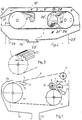
- the two dewatering rollers 1 and 2 of FIG. 1 are wrapped in a screen belt 6.
- the suspension preferably a fiber suspension made of paper fibers
- a material feed nozzle 3 which has an upper lip 4 and a lower lip 5, which is located close to the roller surface extend back and deep into the gusset area.
- the part of the fiber suspension that splashes through the sieve belt is collected by the collecting plate 34 and discharged downwards to the bottom region of the housing 14 - which generally consists of sheet metal.
- the transverse grooves 21 of this first dewatering roller 1 significantly increase the amount of dewatered material.
- the second dewatering roller 2 like the first dewatering roller in general, is hollow and has dewatering bores 18 in its jacket.
- the wire 6 is deflected by 11th and 12 redirected.
- the roller 12 is arranged as a press roller.
- a scraper 7 removes the dewatered material from the dewatering roller 2 and the scraper 8 from the screen belt 6 in the area of the press roller 12.
- a screw conveyor 9 also serves to discharge the dewatered substance from the machine within a conveyor trough 10. The filtrate is discharged through the nozzle 23.
- Fig. 2 a somewhat simplified device is shown, in which the deflection rollers are not available. Otherwise, it consists of the same components and has only in the area of the first dewatering roller a discharge plate 17, which, together with an inclined part 16 of the cover 15 of the machine in the area of the feed nozzle 3 ', derives the portion of the suspension which has passed through the sieve belt 6'. You can e.g. by means of a pump (not shown here) return to the inner area of the sieve belt 6 'and spray onto the lower sieve belt pull.
- a pump not shown here
- the holes 18 of the second roller also allow air to enter, so that there is no negative pressure during centrifugal force dewatering between the fabric web and the roller jacket, which would impair the dewatering.
- the dimensions of the cross section of the longitudinal grooves 20 of the first roller 1 are between 8 and 35, preferably 30 mm, i.e. the cross section is between 200 and 1000, preferably 800 mm2.
- the diameter of the first roller 1 is generally at least 800 mm, so that there are at least 35 longitudinal grooves.
- the pitch t (distance of corresponding points of the adjacent grooves) is a maximum of 70 mm (see FIG. 3).
- Fig. 2 supports 24 and 25 are still drawn for the housing 14 'of the drainage device.
- the sieve belt can still be cleaned by a spray device 28, which in the simplest case can consist of a tube with spray openings at the bottom of it.
Landscapes
- Paper (AREA)
- Treatment Of Fiber Materials (AREA)
- Filtration Of Liquid (AREA)
- Rolls And Other Rotary Bodies (AREA)
- Separation Using Semi-Permeable Membranes (AREA)
- Polymerisation Methods In General (AREA)
- Bridges Or Land Bridges (AREA)
- Polishing Bodies And Polishing Tools (AREA)
Description
- Die Erfindung betrifft eine Einrichtung zum Eindicken von Fasersuspensionen entsprechend dem Oberbegriff des Patentanspruchs 1. Eine solche Einrichtung ist bekannt aus der US-PS 47 22 793. Bei der einen Variante gemäß dieser Patentschrift ist als erste Entwässerungseinrichtung eine mit Umfangsrillen versehene Walze vorgesehen, um deren Umfang das Siebband mit einem Umschlingungswinkel von etwa 180° geführt ist. Es ist eine zweite, parallel zu dieser ersten angeordnete Walze vorhanden, die entweder eine glatte Oberfläche hat oder ebenfalls mit Umfangsrillen versehen sein kann. Hauptsächlich soll bei dieser Einrichtung die Entwässerung durch die Zentrifugalkraft, die durch relativ große Umfangsgeschwindigkeit der Walzen erzeugt wird, bewirkt werden. Die Umfangsrillen in den Walzen sollen die Menge an entwässertem Stoff erhöhen, jedoch besteht der Nachteil, daß nur in dem Bereich der Nuten eine relativ große Stoffmenge eingebracht werden kann, während in den dazwischen befindlichen Bereichen die Stoffmenge relativ gering ist. Ferner dürfen zur Erzielung einer guten Entwässerungswirkung die Nuten auch nicht zu tief sein, so daß auch dadurch der Stoffmenge gewisse enge Grenzen gesetzt sind.
- Ferner ist die Laufzeit (Lebensdauer) des Siebbandes durch die (Rückwirkung) Einwirkung der Rillen und Nuten stark beeinträchtigt.
- Ferner ist die Entwässerungswirkung an der zweiten Walze aufgrund der Fliehkraft der Walzen kleiner als bei der ersten Walze.
- Es sind auch schon andere, als Banddruckfilter bezeichnete Eindickeinrichtungen bekanntgeworden, bei denen eine perforierte Walze verwendet wird, wie z.B. aus der DE-AS 21 38 072 hervorgeht. In der DE-AS 20 47 007 ist dazu in einer vergleichbaren Einrichtung ausgeführt, daß diese Walze auch eine glatte Oberfläche haben kann. Die Stoffzuführung bei solchen Eindickeinrichtungen erfolgt im allgemeinen über eine Düse mit einem schmalen, schlitzförmigen Austrittsquerschnitt, wie z.B. aus der US-PS 15 95 894 oder 23 65 658 hervorgeht.
- Die Aufgabe der Erfindung ist es, eine Einrichtung zum Eindicken anzugeben, bei der die Entwässerungswirkung vorteilhaft gesteuert werden kann, wobei ein einfacher Aufbau der gesamten Einrichtung erreicht werden soll.
- Diese Aufgabe wird erfindungsgemäß bei einer Einrichtung der eingangs genannten Art durch den kennzeichnenden Teil des Patentanspruchs 1 gelöst.
- Eine besonders vorteilhafte Ausführungsform ergibt sich aus Anspruch 2.
- Durch die Quernutung der ersten Entwässerungswalze kann eine hohe Stoffmenge in den Spalt zwischen dem Siebband und der Walzenoberfläche eingebracht werden, so daß sich hier eine starke Entwässerungsleistung ergibt. Ebenso wird die Entwässerungsleistung an der zweiten Walze durch die Entwässerungslöcher derselben erhöht. Bei der Verwendung von zwei zusätzlichen Umlenkwalzen ist die Abnahme des entwässerten Stoffes vom Sieb im Bereich der zweiten Entwässerungswalze verbessert bzw. erleichtert.
- Wird die erste Umlenkwalze praktisch noch als Abgautsch- oder Preßwalze benutzt, kann man an dieser Stelle in dem Zwickel zwischen zweiter Entwässerungswalze und erster Umlenkwalze durch einen Absaugapparat mit einer schnabelförmigen Absaugmündung das Filtrat aus dem Walzenbereich entfernen und abführen.
- Weitere vorteihafte Ansgestaltungen der Erfindung sind Gegenstand der Ansprüche 3 bis 7.
- Nachfolgend wird die Erfindung anhand zwei in den Figuren der Zeichnung dargestellter Ausführungsbeispiele erläutert.
- In den beiden Figuren sind einander entsprechende Teile mit den gleichen Bezugszeichen, jedoch in Figur 2 mit einem Apostroph versehen, gekennzeichnet.
- Die beiden Entwässerungswalzen 1 und 2 von Fig. 1 sind von einem Siebband 6 umschlungen. In dem Zwickelbereich zwischen dem auf die erste Entwässerungswalze 1 auflaufenden Siebband und dem zu diesem hinlaufenden Oberflächenbereich wird die Suspension, vorzugsweise eine Fasersuspension aus Papierfasern, mittels Stoffzuführdüse 3 zugeführt, die eine Oberlippe 4 und eine Unterlippe 5 aufweist, welche sich bis dicht an die Walzenoberfläche hin und tief in den Zwickelbereich hinein erstrecken. Der Teil der Fasersuspension, der durch das Siebband hindurchspritzt, wird durch das Auffangblech 34 aufgefangen und nach unten zum Bodenbereich des Gehäuses 14 - das im allgemeinen aus Blech besteht - abgeleitet. Die Quernuten 21 dieser ersten Entwässerungswalze 1 erhöhen erheblich die entwässerte Stoffmenge. Die zweite Entwässerungswalze 2 ist wie im allgemeinen auch die erste Entwässerungswalze hohl ausgeführt und weist Entwässerungsbohrungen 18 in ihrem Mantel auf. Das Siebband 6 wird durch Umlenkwalzen 11 und 12 umgelenkt. Dabei ist die Walze 12 als Preßwalze angeordnet. Ein Schaber 7 nimmt den entwässerten Stoff von der Entwässerungswalze 2 und der Schaber 8 von dem Siebband 6 in dem Bereich der Preßwalze 12 ab. Eine Förderschnecke 9 dient dazu, innerhalb eines Fördertroges 10 den entwässerten Stoff gleichfalls aus der Maschine abzuleiten. Das Filtrat wird durch den Stutzen 23 abgeleitet.
- In Fig. 2 ist eine etwas vereinfachte Einrichtung dargestellt, bei der die Umlenkwalzen nicht vorhanden sind. Sie besteht ansonsten aus den gleichen Bauteilen und weist nur im Bereich der ersten Entwässerungswalze ein Ableitblech 17 auf, das zusammen mit einem schrägen Teil 16 des Deckels 15 der Maschine im Bereich der Zuführdüse 3′ den durch das Siebband 6′ hindurchgetretenen Anteil der Suspension ableitet. Man kann diesen z.B. mittels Pumpe (hier nicht dargestellt) in den inneren Bereich des Siebbandes 6′ zurückführen und auf den unteren Siebbandzug aufsprühen.
- Die Bohrungen 18 der zweiten Walze (was auch für Fig. 1 gilt) ermöglichen auch Luftzutritt, so daß bei der Fliehkraftentwässerung zwischen Stoffbahn und Walzenmantel kein Unterdruck auftritt, der die Entwässerung beeinträchtigen würde.
- Die Abmessungen des Querschnitts der Längsnuten 20 der ersten Walze 1 betragen zwischen 8 und 35, vorzugsweise 30 mm, d.h. der Querschnitt beträgt zwischen 200 und 1000, vorzugsweise 800 mm².
- Der Durchmesser der ersten Walze 1 beträgt im allgemeinen mindestens 800 mm, so daß mindestens 35 Längsnuten vorhanden sind. Die Teilung t (Abstand entsprechender Stellen der benachbarten Nuten) beträgt maximal 70 mm (siehe Fig. 3).
- In Fig. 2 sind noch Stützen 24 und 25 für das Gehäuse 14′ der Entwässerungseinrichtung gezeichnet. Das Siebband kann noch gereinigt werden durch eine Sprühvorrichtung 28, die im einfachsten Fall aus einem Rohr mit unten an diesem angebrachten Sprühöffnungen bestehen kann.
Claims (7)
- Einrichtung zum Eindicken von aufgeschlämmten Stoffen, insbesondere Fasersuspensionen, mit zwei parallelen Walzen (1, 2) mit im wesentlichen horizontaler Achse, die von einem Siebband (6) umschlungen sind und von denen mindestens eine einen Antrieb aufweist, wobei eine Stoffzuführeinrichtung (5) zwischen dem Siebband (6) und dem auf dieses zulaufenden Oberflächenbereich der ersten Walze (1) vorgesehen ist, die einen Stoffstrahl in den Zwickelbereich richtet, sowie mindestens einer Stoffabnahme- und einer Stoffabfuhreinrichtung (7, 10) im Bereich der zweiten Walze (2), dadurch gekennzeichnet, daß die erste Walze (1) mit achsparallelen Oberflächennuten (20) eines Querschnitts von 200 bis 1000, vorzugsweise 800 mm² versehen ist.
- Einrichtung nach Anspruch 1, dadurch gekennzeichnet, daß zumindest die zweite Walze (2) hohl ausgeführt und mit Mantelbohrungen (18) versehen ist.
- Einrichtung nach Anspruch 1 oder 2, dadurch gekennzeichnet, daS die Nuten im wesentlichen quadratisch oder rechteckig sind mit einer maximalen Querschnittsabmessung von 35 mm und die Teilung (t) maximal 70 mm und der Durchmesser der ersten Walze (1) mindestens 800 mm beträgt.
- Einrichtung nach einem der Ansprüche 1 bis 3, dadurch gekennzeichnet, daß im Bereich der zweiten Walze (2) zwei Umlenkwalzen (11, 12) vorgesehen sind, von denen die der zweiten Walze (2) nähere als Preßwalze in bezug auf diese zweite Walze ausgeführt ist.
- Einrichtung nach Anspruch 4, dadurch gekennzeichnet, daß im Zwickelbereich zwischen der Preßwalze 12 und der zweiten Walze (2) eine Absaugeinrichtung (13) für das Filtrat vorgesehen ist.
- Einrichtung nach einem der Ansprüche 1 bis 5, dadurch gekennzeichnet, daß sowohl im Bereich der Preßwalze (12) als auch der zweiten Walze (2) Abschabeinrichtungen (7, 8) vorgesehen sind, wovon die der Preßwalze zugeordnete Abschabeinrichtung am Siebband (6) angreift.
- Einrichtung nach einem der Ansprüche 1 bis 6, dadurch gekennzeichnet, daß die Walzen (1, 2) im wesentlichen auf einem gleichen Höhenniveau angeordnet sind und der Umschlingungswinkel der zweiten Walze (2) durch das Siebband (6) zwischen 140 und 160° beträgt.
Priority Applications (1)
| Application Number | Priority Date | Filing Date | Title |
|---|---|---|---|
| AT9090103408T ATE105346T1 (de) | 1989-03-01 | 1990-02-22 | Einrichtung zum eindicken von fasersuspensionen. |
Applications Claiming Priority (2)
| Application Number | Priority Date | Filing Date | Title |
|---|---|---|---|
| DE3906452A DE3906452A1 (de) | 1989-03-01 | 1989-03-01 | Einrichtung zum eindicken von fasersuspensionen |
| DE3906452 | 1989-03-01 |
Publications (3)
| Publication Number | Publication Date |
|---|---|
| EP0400270A2 EP0400270A2 (de) | 1990-12-05 |
| EP0400270A3 EP0400270A3 (de) | 1991-09-25 |
| EP0400270B1 true EP0400270B1 (de) | 1994-05-04 |
Family
ID=6375226
Family Applications (1)
| Application Number | Title | Priority Date | Filing Date |
|---|---|---|---|
| EP90103408A Expired - Lifetime EP0400270B1 (de) | 1989-03-01 | 1990-02-22 | Einrichtung zum Eindicken von Fasersuspensionen |
Country Status (4)
| Country | Link |
|---|---|
| EP (1) | EP0400270B1 (de) |
| AT (1) | ATE105346T1 (de) |
| DE (2) | DE3906452A1 (de) |
| ES (1) | ES2052085T3 (de) |
Family Cites Families (7)
| Publication number | Priority date | Publication date | Assignee | Title |
|---|---|---|---|---|
| US2365658A (en) * | 1939-06-20 | 1944-12-19 | American Voith Contact Co Inc | Apparatus for the removal of water, liquors, or other liquids from soaked masses of fibrous materials |
| DE2138072B2 (de) * | 1971-07-30 | 1973-10-31 | J.M. Voith Gmbh, 7920 Heidenheim | Banddruckfilter |
| US3877366A (en) * | 1973-12-28 | 1975-04-15 | Nivoba Bv | Press Filter |
| DE3123131C2 (de) * | 1981-06-11 | 1986-01-09 | J.M. Voith Gmbh, 7920 Heidenheim | Entwässerungswalze mit Wasserabführungselement für ein Papiermaschinen-Siebband |
| CH653912A5 (de) * | 1982-02-16 | 1986-01-31 | Von Roll Ag | Bandfilterpresse zum filtrieren einer truebe. |
| DE8528848U1 (de) * | 1985-10-10 | 1985-11-28 | Gebr. Bellmer GmbH + Co KG Maschinenfabrik, 7532 Niefern | Preßwalze, insbesondere für den Hochdruckbereich in Bandfilterpressen |
| US4722793A (en) * | 1986-07-03 | 1988-02-02 | The Black Clawson Company | Apparatus and method for thickening pulp and paper stock |
-
1989
- 1989-03-01 DE DE3906452A patent/DE3906452A1/de not_active Ceased
-
1990
- 1990-02-22 ES ES90103408T patent/ES2052085T3/es not_active Expired - Lifetime
- 1990-02-22 DE DE59005584T patent/DE59005584D1/de not_active Expired - Fee Related
- 1990-02-22 AT AT9090103408T patent/ATE105346T1/de not_active IP Right Cessation
- 1990-02-22 EP EP90103408A patent/EP0400270B1/de not_active Expired - Lifetime
Also Published As
| Publication number | Publication date |
|---|---|
| EP0400270A3 (de) | 1991-09-25 |
| EP0400270A2 (de) | 1990-12-05 |
| ES2052085T3 (es) | 1994-07-01 |
| DE3906452A1 (de) | 1990-09-13 |
| DE59005584D1 (de) | 1994-06-09 |
| ATE105346T1 (de) | 1994-05-15 |
Similar Documents
| Publication | Publication Date | Title |
|---|---|---|
| DE2323519B2 (de) | Keilpresse zum kontinuierlichen entwaessern einer faserstoffbahn | |
| CH691183A5 (de) | Vorrichtung an einer Karde. | |
| CH653912A5 (de) | Bandfilterpresse zum filtrieren einer truebe. | |
| DE2758336C2 (de) | Florabnahmevorrichtung am Abnehmer einer Karde | |
| DE3410443C2 (de) | Vorrichtung zum Einleiten eines von einer Krempel über ein Transportband herangeführten Flores in einen Kalander | |
| DE2000661B2 (de) | Bahnbildungszone einer Papiermaschine | |
| EP0400270A2 (de) | Einrichtung zum Eindicken von Fasersuspensionen | |
| DE3120073A1 (de) | Doppelsiebpapiermaschine | |
| DE3532458C2 (de) | ||
| EP0985754A1 (de) | Streckwerk für Spinnereimaschinen mit einer Verdichtungsvorrichtung | |
| DE3222428A1 (de) | Doppelsieb-papiermaschine | |
| EP0826819A2 (de) | Vorrichtung zum Entwässern einer Faserstoffsuspension | |
| DE19753604C2 (de) | Verfahren zum Entwässern einer Faserstoffsuspension | |
| EP0031445B1 (de) | Verfahren zur Beeinflussung eines vorentwässerten Faservlieses auf einem Sieb und Vorrichtung zur Durchführung des Verfahrens | |
| DE19805593A1 (de) | Eindicker | |
| DE4105803A1 (de) | Entwaesserungseinrichtung fuer suspensionen | |
| EP0887463A2 (de) | Einrichtung zur Entwässerung eines Papiermaschinenfilzes | |
| AT375695B (de) | Doppelsieb-papiermaschine | |
| DE3008468A1 (de) | Papierformwalze | |
| DE2105613B2 (de) | Siebpartie einer Papiermaschine | |
| AT276056B (de) | Vorrichtung zum selbsttätigen Überführen einer vom Langsieb einer Langsiebpapiermaschine getragenen nassen Faserstoffbahn auf eine durchlässige Abnahmebahn | |
| DE1800804C3 (de) | Rundsiebpapiermaschine | |
| DE9102171U1 (de) | Entwässerungseinrichtung für Suspensionen | |
| AT399293B (de) | Verfahren zum eindicken einer faserstoffsuspension bzw. zum trennen einer faserstoffsuspension von feinstoffen und vorrichtung zum durchführen des verfahrens | |
| DE2725351A1 (de) | Siebpartie einer papiermaschine |
Legal Events
| Date | Code | Title | Description |
|---|---|---|---|
| PUAI | Public reference made under article 153(3) epc to a published international application that has entered the european phase |
Free format text: ORIGINAL CODE: 0009012 |
|
| AK | Designated contracting states |
Kind code of ref document: A2 Designated state(s): AT CH DE ES FR GB LI NL SE |
|
| PUAL | Search report despatched |
Free format text: ORIGINAL CODE: 0009013 |
|
| AK | Designated contracting states |
Kind code of ref document: A3 Designated state(s): AT CH DE ES FR GB LI NL SE |
|
| 17P | Request for examination filed |
Effective date: 19911128 |
|
| 17Q | First examination report despatched |
Effective date: 19931015 |
|
| GRAA | (expected) grant |
Free format text: ORIGINAL CODE: 0009210 |
|
| AK | Designated contracting states |
Kind code of ref document: B1 Designated state(s): AT CH DE ES FR GB LI NL SE |
|
| REF | Corresponds to: |
Ref document number: 105346 Country of ref document: AT Date of ref document: 19940515 Kind code of ref document: T |
|
| GBT | Gb: translation of ep patent filed (gb section 77(6)(a)/1977) |
Effective date: 19940511 |
|
| REF | Corresponds to: |
Ref document number: 59005584 Country of ref document: DE Date of ref document: 19940609 |
|
| ET | Fr: translation filed | ||
| REG | Reference to a national code |
Ref country code: ES Ref legal event code: FG2A Ref document number: 2052085 Country of ref document: ES Kind code of ref document: T3 |
|
| EAL | Se: european patent in force in sweden |
Ref document number: 90103408.2 |
|
| PGFP | Annual fee paid to national office [announced via postgrant information from national office to epo] |
Ref country code: NL Payment date: 19950228 Year of fee payment: 6 |
|
| PLBE | No opposition filed within time limit |
Free format text: ORIGINAL CODE: 0009261 |
|
| STAA | Information on the status of an ep patent application or granted ep patent |
Free format text: STATUS: NO OPPOSITION FILED WITHIN TIME LIMIT |
|
| 26N | No opposition filed | ||
| PG25 | Lapsed in a contracting state [announced via postgrant information from national office to epo] |
Ref country code: NL Effective date: 19960901 |
|
| NLV4 | Nl: lapsed or anulled due to non-payment of the annual fee |
Effective date: 19960901 |
|
| PGFP | Annual fee paid to national office [announced via postgrant information from national office to epo] |
Ref country code: GB Payment date: 19970121 Year of fee payment: 8 |
|
| PGFP | Annual fee paid to national office [announced via postgrant information from national office to epo] |
Ref country code: AT Payment date: 19970123 Year of fee payment: 8 |
|
| PGFP | Annual fee paid to national office [announced via postgrant information from national office to epo] |
Ref country code: FR Payment date: 19970214 Year of fee payment: 8 |
|
| PGFP | Annual fee paid to national office [announced via postgrant information from national office to epo] |
Ref country code: ES Payment date: 19970219 Year of fee payment: 8 |
|
| PGFP | Annual fee paid to national office [announced via postgrant information from national office to epo] |
Ref country code: SE Payment date: 19970221 Year of fee payment: 8 |
|
| PGFP | Annual fee paid to national office [announced via postgrant information from national office to epo] |
Ref country code: DE Payment date: 19970326 Year of fee payment: 8 Ref country code: CH Payment date: 19970326 Year of fee payment: 8 |
|
| PG25 | Lapsed in a contracting state [announced via postgrant information from national office to epo] |
Ref country code: GB Free format text: LAPSE BECAUSE OF NON-PAYMENT OF DUE FEES Effective date: 19980222 Ref country code: AT Free format text: LAPSE BECAUSE OF NON-PAYMENT OF DUE FEES Effective date: 19980222 |
|
| PG25 | Lapsed in a contracting state [announced via postgrant information from national office to epo] |
Ref country code: SE Free format text: LAPSE BECAUSE OF NON-PAYMENT OF DUE FEES Effective date: 19980223 Ref country code: ES Free format text: LAPSE BECAUSE OF EXPIRATION OF PROTECTION Effective date: 19980223 |
|
| PG25 | Lapsed in a contracting state [announced via postgrant information from national office to epo] |
Ref country code: LI Free format text: LAPSE BECAUSE OF NON-PAYMENT OF DUE FEES Effective date: 19980228 Ref country code: FR Free format text: THE PATENT HAS BEEN ANNULLED BY A DECISION OF A NATIONAL AUTHORITY Effective date: 19980228 Ref country code: CH Free format text: LAPSE BECAUSE OF NON-PAYMENT OF DUE FEES Effective date: 19980228 |
|
| GBPC | Gb: european patent ceased through non-payment of renewal fee |
Effective date: 19980222 |
|
| REG | Reference to a national code |
Ref country code: CH Ref legal event code: PL |
|
| EUG | Se: european patent has lapsed |
Ref document number: 90103408.2 |
|
| PG25 | Lapsed in a contracting state [announced via postgrant information from national office to epo] |
Ref country code: DE Free format text: LAPSE BECAUSE OF NON-PAYMENT OF DUE FEES Effective date: 19981103 |
|
| REG | Reference to a national code |
Ref country code: FR Ref legal event code: ST |
|
| REG | Reference to a national code |
Ref country code: ES Ref legal event code: FD2A Effective date: 20000301 |