EP0400274A2 - Récipient de coulée pour machines à couler sous pression à chambre chaude - Google Patents
Récipient de coulée pour machines à couler sous pression à chambre chaude Download PDFInfo
- Publication number
- EP0400274A2 EP0400274A2 EP90103944A EP90103944A EP0400274A2 EP 0400274 A2 EP0400274 A2 EP 0400274A2 EP 90103944 A EP90103944 A EP 90103944A EP 90103944 A EP90103944 A EP 90103944A EP 0400274 A2 EP0400274 A2 EP 0400274A2
- Authority
- EP
- European Patent Office
- Prior art keywords
- casting
- elbow
- container according
- casting container
- chamber
- Prior art date
- Legal status (The legal status is an assumption and is not a legal conclusion. Google has not performed a legal analysis and makes no representation as to the accuracy of the status listed.)
- Granted
Links
Images

Classifications
-
- B—PERFORMING OPERATIONS; TRANSPORTING
- B22—CASTING; POWDER METALLURGY
- B22D—CASTING OF METALS; CASTING OF OTHER SUBSTANCES BY THE SAME PROCESSES OR DEVICES
- B22D17/00—Pressure die casting or injection die casting, i.e. casting in which the metal is forced into a mould under high pressure
- B22D17/02—Hot chamber machines, i.e. with heated press chamber in which metal is melted
- B22D17/04—Plunger machines
-
- B—PERFORMING OPERATIONS; TRANSPORTING
- B22—CASTING; POWDER METALLURGY
- B22D—CASTING OF METALS; CASTING OF OTHER SUBSTANCES BY THE SAME PROCESSES OR DEVICES
- B22D17/00—Pressure die casting or injection die casting, i.e. casting in which the metal is forced into a mould under high pressure
- B22D17/02—Hot chamber machines, i.e. with heated press chamber in which metal is melted
Definitions
- the invention relates to a casting container for hot-chamber die casting machines, which is cast in one piece from a heat-resistant tool steel and has a casting chamber with the treads for the casting piston, as well as a riser hole arranged approximately parallel to it, which opens into the casting chamber at one end and at the opposite end is provided with a mouthpiece for attaching a nozzle.
- the riser hole is cast in with the aid of inserted cores.
- the riser bore is led axially out of the casting container at one end and is closed there by an inserted screw.
- the connection to the casting chamber is made via a channel running perpendicular to the riser bore, which was also made by an inserted core and also through to the outside a screw must be closed. Both the riser hole and the transverse channel must therefore be machined in a relatively complex manner. This also applies to the connection cone for the nozzle provided in the area of the mouthpiece.
- the invention is based on the object of designing a casting container of the type mentioned at the outset in such a way that pressure losses can be avoided and complex machining operations can be saved.
- a cast-in tube is provided as a riser hole in a casting container of the type mentioned at the beginning, which is bent in the region of the mouth towards the casting chamber and in the region of the mouthpiece, and which is welded together at least from two parts.
- This configuration makes it possible, on the one hand, to effect the transition into the parallel part of the riser pipe with the aid of a favorable flow deflection.
- the welded design of the tube makes it possible to choose the geometry of the tube differently and to adapt it to the loads to be expected both for the deflection of the melt and for the loads to be expected due to the temperatures occurring.
- the riser pipe is assembled in a particularly advantageous manner from a first elbow in the area of the mouth to the casting chamber, from a substantially straight pipe section adjoining this and from a second elbow adjoining the pipe section in the area of the mouthpiece.
- both elbows can be individually adapted to the respective requirements without taking into account the dimensions of the straight line in between Pipe piece must be taken.
- the second manifold can, according to the features of claim 3, advantageously also consist of one piece with a receiving cone for the nozzle, so that here too there are no interface problems.
- the wall thickness of the receiving cone can increase towards the opening, so that the wall thickness at the critical point meets the loads that occur.
- subclaims 5 to 7 it is also possible to change the inside diameter of the elbow and to make it smaller in the direction of flow of the melt, so that an adaptation to the fluidic requirements is possible.
- subclaims 8 to 10 it is also possible to make the radii of curvature different and to design the wall thicknesses of the manifold parts differently, and to adapt them to the requirements that arise.
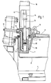
- the hot chamber die casting machine shown in FIG. 1 has a casting container (1) which is inserted from above into a trough (2) in which there is a molten metal.
- the metal to be melted is introduced into the trough through an opening closed with a flap (3).
- the trough (2) is arranged in an oven (4) so that the metal particles which have been introduced can be melted in it.
- a thermometer (5) is immersed, by means of which the temperature prevailing in the area of the casting container (1) can be monitored.
- the casting container (1) which is held by a crossmember (6), has a casting chamber (7) and a riser hole (9) connected to it, which leads to a mouthpiece (10) on which an inclined nozzle (11) is arranged.
- the casting chamber (7) consists of a sleeve-shaped part which is inserted in the casting container (1) and is shown in FIG. 2.
- a casting piston (12) is guided in the casting chamber (7) and is connected to a hydraulic cylinder (15) via a piston rod (13) and a coupling (14).
- the casting piston is in its top dead center position as shown in FIG. 1. Below this dead center position there are several bores (16) distributed uniformly over the circumference in the casting container (1), which connect the casting chamber (7) to the trough (2).
- the metal melt runs through the bores (16) into the casting chamber (7), from which it is pressed out via the riser bore (9) with the nozzle (11) by lowering the casting piston (12).
- the melt can flow back into the area of the riser hole (9) when the casting piston (12) is withdrawn from the nozzle (11), so that it remains within the heated area and does not solidify.
- the inside diameter of the upwardly open casting container (1) widens above the casting chamber (7). This area is also connected to the trough (2) via openings (17), so that the casting piston is also surrounded on its upper side by the melt.
- the casting container (1) shown in FIG. 2 is made as a casting from a heat-resistant tool steel alloy. Cast cast containers have economic advantages over a forged version. Also in modern hot chamber die casting machines, because of the higher casting pressures (up to 400 bar) necessary high-quality hot-work steels can be cast.
- the casting container (1) as shown in Fig. 2, is provided with a riser hole (9) which consists of a co-cast pipe (18) which is welded together from three parts.
- the pipe (18) consists on the one hand of a bend (19) adjoining the casting chamber (7), an adjacent cylindrical pipe section (20) and a second bend (21) adjacent to the pipe section (20) in the region of the mouthpiece (10) ).
- the inside diameter of the first elbow (19) decreases from the mouth (22) to the casting chamber (7) up to the connection to the pipe section (20), which means that the inside diameter of the elbow (19) at the connection point to the pipe section ( 20) corresponds to the inside diameter (d) of the pipe section (20), but has the larger diameter (d 1) at the mouth (22).
- the mouth (22) is opposite an opening in the casting chamber (7) which has a diameter (d0) which is larger than (d1).
- the second elbow (21) also has at its connection to the pipe section (20) the inner diameter (d), in the region of its mouth (23) in a receiving cone (24), however, the diameter (d2), which is smaller than the diameter (d ) is.
- the diameter d1 16 mm
- the diameter d 14 mm
- the diameter d2 12 mm.
- the elbow (21) is provided with a receiving cone (24) for the nozzle (11).
- This receiving cone (24) is arranged in one piece on the manifold (21).
- the cone angle of which can be approximately 5 ° the elbow (21) has an outwardly increasing wall thickness, the outer wall of the receiving cone (24) being at a larger cone angle than the receiving cone (24) itself, in the exemplary embodiment under a cone angle of 10 °, merges into the outer wall of the manifold.
- the second elbow (21) therefore has an outer diameter (D) at the connection point to the pipe section (20) which corresponds to the outer diameter (D) of the pipe section (20) while it has a diameter (D M ) at the mouth (10) has that is much larger.
- the diameter D 24 mm
- the diameter D M 40 mm.
- the radii of curvature of the manifolds (19, 21) are also different. So the first manifold (19) has an inner radius (R1) which is greater than the inner radius (R2) of the second manifold (21); the outer radius of curvature (R3) of the first elbow (19) is larger than the outer radius of curvature (R4) of the second elbow (21).
- the inner radius R1 9 mm
- the outer radius of the first elbow R3 35 mm
- the outer radius of the second elbow R4 31 mm.
- the first elbow (19) which is welded to the pipe section (20) at the point (25), is adapted to the requirements of the flow of the molten metal occurring at this point.
- the 90 ° transition takes place without sharp corners, so that pressure losses or turbulence cannot occur in the melt pressed out of the casting chamber (7).
- the second elbow (21), which is welded to the pipe section (20) at the point (26), is individually adapted to the requirements that arise. Its inner diameter also tapers in the direction of flow, like the inner diameter of the first elbow (19).
- the second elbow (21) is also provided in one piece with the receiving cone (24), so that no difficulties arise at the connection point for the nozzle (11) at this point either.
- the wall thicknesses, in particular of the second elbow (21) in the region of the receiving cone (24) are also selected such that they meet the required requirements Withstand loads without the need for extensive reworking on the finished casting tank.
Landscapes
- Engineering & Computer Science (AREA)
- Mechanical Engineering (AREA)
- Molds, Cores, And Manufacturing Methods Thereof (AREA)
- Casting Support Devices, Ladles, And Melt Control Thereby (AREA)
- Chain Conveyers (AREA)
Applications Claiming Priority (2)
| Application Number | Priority Date | Filing Date | Title |
|---|---|---|---|
| DE3917487 | 1989-05-30 | ||
| DE3917487A DE3917487A1 (de) | 1989-05-30 | 1989-05-30 | Giessbehaelter fuer warmkammer-druckgiessmaschinen |
Publications (3)
| Publication Number | Publication Date |
|---|---|
| EP0400274A2 true EP0400274A2 (fr) | 1990-12-05 |
| EP0400274A3 EP0400274A3 (fr) | 1992-04-08 |
| EP0400274B1 EP0400274B1 (fr) | 1993-12-01 |
Family
ID=6381633
Family Applications (1)
| Application Number | Title | Priority Date | Filing Date |
|---|---|---|---|
| EP90103944A Expired - Lifetime EP0400274B1 (fr) | 1989-05-30 | 1990-03-01 | Récipient de coulée pour machines à couler sous pression à chambre chaude |
Country Status (5)
| Country | Link |
|---|---|
| US (1) | US5072778A (fr) |
| EP (1) | EP0400274B1 (fr) |
| JP (1) | JP3014715B2 (fr) |
| DE (2) | DE3917487A1 (fr) |
| ES (1) | ES2047176T3 (fr) |
Cited By (2)
| Publication number | Priority date | Publication date | Assignee | Title |
|---|---|---|---|---|
| DE4439871C1 (de) * | 1994-11-08 | 1996-01-04 | Friedrich Druckgiestech Gmbh | Gießbehälter |
| IT201700033183A1 (it) * | 2017-03-27 | 2018-09-27 | Flavio Mancini | Impianto per la pressofusione a camera calda di leghe non ferrose |
Families Citing this family (7)
| Publication number | Priority date | Publication date | Assignee | Title |
|---|---|---|---|---|
| IT1260341B (it) * | 1992-05-26 | 1996-04-05 | Pressocolatrice a camera calda per leghe leggere | |
| DE4419848C1 (de) * | 1994-06-07 | 1995-12-21 | Frech Oskar Gmbh & Co | Warmkammer-Druckgießmaschine |
| DE50000293D1 (de) * | 2000-08-21 | 2002-08-22 | Frech Oskar Gmbh & Co | Verfahren zur Herstellung eines Giessbehälters sowie Giessbehälter |
| DE102004027109A1 (de) * | 2004-06-03 | 2005-12-29 | Siempelkamp Giesserei Gmbh | Verfahren zur Herstellung eines eine Gravur aufweisenden, temperierbaren Werkzeugs im Wege des Gießens |
| JP5615640B2 (ja) * | 2010-09-16 | 2014-10-29 | 株式会社広築 | 非鉄金属の溶湯供給装置 |
| CN115889730A (zh) * | 2022-01-10 | 2023-04-04 | 开平市长沙楼冈铸造厂 | 一种压铸机料壶 |
| DE102024109648A1 (de) * | 2024-04-05 | 2025-10-09 | Oskar Ketterer Druckgiesserei Gmbh | Warmkammerdruckguss-Gießbehälter und Verfahren dazu |
Family Cites Families (7)
| Publication number | Priority date | Publication date | Assignee | Title |
|---|---|---|---|---|
| DE1878490U (de) * | 1963-01-03 | 1963-08-29 | Ewald Schulte | Druckgussmaschine zur verarbeitung von zink- oder aehnlichen metallegierungen. |
| DE2143937B2 (de) * | 1971-09-02 | 1977-05-18 | Oskar Frech, Werkzeugbau, 7061 Weiler | Giessbehaelter fuer eine warmkammer- druckgiessmaschine |
| JPS52140420A (en) * | 1976-05-20 | 1977-11-24 | Toshiba Machine Co Ltd | Injection pump device for molten metal |
| JPS555139A (en) * | 1978-06-24 | 1980-01-16 | Toshiba Mach Co Ltd | Injection pump device for molten metal |
| US4556098A (en) * | 1978-08-18 | 1985-12-03 | Laboratoire Suisse De Recherches Horlogeres | Hot chamber die casting of aluminum and its alloys |
| US4587177A (en) * | 1985-04-04 | 1986-05-06 | Imperial Clevite Inc. | Cast metal composite article |
| CN102574976B (zh) | 2009-10-05 | 2014-01-08 | 旭硝子株式会社 | 软质聚氨酯泡沫塑料的制造方法及片材 |
-
1989
- 1989-05-30 DE DE3917487A patent/DE3917487A1/de not_active Withdrawn
-
1990
- 1990-03-01 ES ES90103944T patent/ES2047176T3/es not_active Expired - Lifetime
- 1990-03-01 DE DE90103944T patent/DE59003655D1/de not_active Expired - Fee Related
- 1990-03-01 EP EP90103944A patent/EP0400274B1/fr not_active Expired - Lifetime
- 1990-04-10 JP JP2093291A patent/JP3014715B2/ja not_active Expired - Fee Related
- 1990-05-22 US US07/526,588 patent/US5072778A/en not_active Expired - Lifetime
Cited By (5)
| Publication number | Priority date | Publication date | Assignee | Title |
|---|---|---|---|---|
| DE4439871C1 (de) * | 1994-11-08 | 1996-01-04 | Friedrich Druckgiestech Gmbh | Gießbehälter |
| IT201700033183A1 (it) * | 2017-03-27 | 2018-09-27 | Flavio Mancini | Impianto per la pressofusione a camera calda di leghe non ferrose |
| WO2018178815A1 (fr) * | 2017-03-27 | 2018-10-04 | Flavio Mancini | Appareil pour la coulée sous pression en chambre chaude d'alliages non ferreux |
| CN110461502A (zh) * | 2017-03-27 | 2019-11-15 | 弗拉维奥·曼奇尼 | 用于有色合金的热室压铸的设备 |
| US10850323B2 (en) | 2017-03-27 | 2020-12-01 | Flavio Mancini | Apparatus for the hot-chamber die casting of non ferrous alloys |
Also Published As
| Publication number | Publication date |
|---|---|
| JPH035056A (ja) | 1991-01-10 |
| JP3014715B2 (ja) | 2000-02-28 |
| DE59003655D1 (de) | 1994-01-13 |
| US5072778A (en) | 1991-12-17 |
| EP0400274A3 (fr) | 1992-04-08 |
| DE3917487A1 (de) | 1990-12-06 |
| EP0400274B1 (fr) | 1993-12-01 |
| ES2047176T3 (es) | 1994-02-16 |
Similar Documents
| Publication | Publication Date | Title |
|---|---|---|
| EP0051310B1 (fr) | Appareil de moulage par injection pour la coulée de pièces | |
| DE69702984T2 (de) | Tauchgiessrohr zum stranggiessen von dünnbrammen | |
| EP0400274B1 (fr) | Récipient de coulée pour machines à couler sous pression à chambre chaude | |
| DE3629696C2 (fr) | ||
| DE1452239A1 (de) | Strangpressform und Verfahren zum Strangpressen | |
| DE69819116T2 (de) | Getriebeschaltgabel und deren Herstellungsverfahren | |
| DE4315709C2 (de) | Schiebeausguß für ein Stahlschmelze-Aufnahmegefäß | |
| AT400311B (de) | Stranggiesskokille | |
| DE2412424A1 (de) | Verfahren zum stranggiessen eines laenglichen metallgegenstands und vorrichtung zur durchfuehrung des verfahrens | |
| DE2548215A1 (de) | Niederdruck-schnellgussanlage | |
| DE4317774A1 (de) | Feuerfest-Schieberplatte | |
| DE4203964A1 (de) | Ringmantel fuer eine walze zum kontinuierlichen giessen | |
| DE3426107C2 (de) | Schiebeverschluß für den horizontalen Ausguß von Nichteisen-Metallschmelze enthaltenden Gefässen | |
| DE4420199C2 (de) | Gießpfannen- oder Tundish-Schieber | |
| DE1483608C3 (de) | Druckgießmaschine | |
| DE69401773T2 (de) | Giessrohr | |
| DE2553087A1 (de) | Form zum kontinuierlichen giessen von metall | |
| DE10246701B4 (de) | Spritzgießvorrichtung und Düse mit einer Spaltdichtung zwischen Düsenbauteilen | |
| AT526300B1 (de) | Schmelzetransportvorrichtung, sowie eine mit der Lanze ausgestattete Schmelzetransportvorrichtung, sowie ein Verfahren zum Herstellen einer Lanze für die Schmelzetransportvorrichtung | |
| DE102022101985B4 (de) | GIEßKAMMER FÜR DRUCKGIEßVORRICHTUNG UND DRUCKGIEßVORRICHTUNG MIT EINER SOLCHEN GIEßKAMMER | |
| DE4439871C1 (de) | Gießbehälter | |
| DE2143937B2 (de) | Giessbehaelter fuer eine warmkammer- druckgiessmaschine | |
| EP0795387B1 (fr) | Dispositif de moulage par injection de matières plastiques | |
| EP1193008B1 (fr) | Procédé pour la production d' un récipient de coulée et récipient de coulée | |
| EP0972595B1 (fr) | Creuset de maintien |
Legal Events
| Date | Code | Title | Description |
|---|---|---|---|
| PUAI | Public reference made under article 153(3) epc to a published international application that has entered the european phase |
Free format text: ORIGINAL CODE: 0009012 |
|
| AK | Designated contracting states |
Kind code of ref document: A2 Designated state(s): CH DE ES FR GB IT LI |
|
| PUAL | Search report despatched |
Free format text: ORIGINAL CODE: 0009013 |
|
| AK | Designated contracting states |
Kind code of ref document: A3 Designated state(s): CH DE ES FR GB IT LI |
|
| 17P | Request for examination filed |
Effective date: 19920430 |
|
| 17Q | First examination report despatched |
Effective date: 19920807 |
|
| GRAA | (expected) grant |
Free format text: ORIGINAL CODE: 0009210 |
|
| ITF | It: translation for a ep patent filed | ||
| AK | Designated contracting states |
Kind code of ref document: B1 Designated state(s): CH DE ES FR GB IT LI |
|
| REF | Corresponds to: |
Ref document number: 59003655 Country of ref document: DE Date of ref document: 19940113 |
|
| REG | Reference to a national code |
Ref country code: ES Ref legal event code: FG2A Ref document number: 2047176 Country of ref document: ES Kind code of ref document: T3 |
|
| GBT | Gb: translation of ep patent filed (gb section 77(6)(a)/1977) |
Effective date: 19940216 |
|
| ET | Fr: translation filed | ||
| PLBE | No opposition filed within time limit |
Free format text: ORIGINAL CODE: 0009261 |
|
| STAA | Information on the status of an ep patent application or granted ep patent |
Free format text: STATUS: NO OPPOSITION FILED WITHIN TIME LIMIT |
|
| 26N | No opposition filed | ||
| REG | Reference to a national code |
Ref country code: GB Ref legal event code: IF02 |
|
| REG | Reference to a national code |
Ref country code: CH Ref legal event code: NV Representative=s name: ZIMMERLI, WAGNER & PARTNER AG |
|
| PGFP | Annual fee paid to national office [announced via postgrant information from national office to epo] |
Ref country code: ES Payment date: 20080326 Year of fee payment: 19 Ref country code: CH Payment date: 20080320 Year of fee payment: 19 |
|
| PGFP | Annual fee paid to national office [announced via postgrant information from national office to epo] |
Ref country code: GB Payment date: 20080318 Year of fee payment: 19 |
|
| PGFP | Annual fee paid to national office [announced via postgrant information from national office to epo] |
Ref country code: DE Payment date: 20080416 Year of fee payment: 19 Ref country code: FR Payment date: 20080314 Year of fee payment: 19 |
|
| PGFP | Annual fee paid to national office [announced via postgrant information from national office to epo] |
Ref country code: IT Payment date: 20080329 Year of fee payment: 19 |
|
| REG | Reference to a national code |
Ref country code: CH Ref legal event code: PL |
|
| GBPC | Gb: european patent ceased through non-payment of renewal fee |
Effective date: 20090301 |
|
| REG | Reference to a national code |
Ref country code: FR Ref legal event code: ST Effective date: 20091130 |
|
| PG25 | Lapsed in a contracting state [announced via postgrant information from national office to epo] |
Ref country code: LI Free format text: LAPSE BECAUSE OF NON-PAYMENT OF DUE FEES Effective date: 20090331 Ref country code: CH Free format text: LAPSE BECAUSE OF NON-PAYMENT OF DUE FEES Effective date: 20090331 Ref country code: DE Free format text: LAPSE BECAUSE OF NON-PAYMENT OF DUE FEES Effective date: 20091001 |
|
| PG25 | Lapsed in a contracting state [announced via postgrant information from national office to epo] |
Ref country code: FR Free format text: LAPSE BECAUSE OF NON-PAYMENT OF DUE FEES Effective date: 20091123 Ref country code: GB Free format text: LAPSE BECAUSE OF NON-PAYMENT OF DUE FEES Effective date: 20090301 |
|
| REG | Reference to a national code |
Ref country code: ES Ref legal event code: FD2A Effective date: 20090302 |
|
| PG25 | Lapsed in a contracting state [announced via postgrant information from national office to epo] |
Ref country code: ES Free format text: LAPSE BECAUSE OF NON-PAYMENT OF DUE FEES Effective date: 20090302 |
|
| PG25 | Lapsed in a contracting state [announced via postgrant information from national office to epo] |
Ref country code: IT Free format text: LAPSE BECAUSE OF NON-PAYMENT OF DUE FEES Effective date: 20090301 |