EP0400336A2 - Appareil d'entrée/de sortie d'informations, en particulier de données de patients - Google Patents
Appareil d'entrée/de sortie d'informations, en particulier de données de patients Download PDFInfo
- Publication number
- EP0400336A2 EP0400336A2 EP19900108145 EP90108145A EP0400336A2 EP 0400336 A2 EP0400336 A2 EP 0400336A2 EP 19900108145 EP19900108145 EP 19900108145 EP 90108145 A EP90108145 A EP 90108145A EP 0400336 A2 EP0400336 A2 EP 0400336A2
- Authority
- EP
- European Patent Office
- Prior art keywords
- input
- output medium
- image information
- data
- graphic output
- Prior art date
- Legal status (The legal status is an assumption and is not a legal conclusion. Google has not performed a legal analysis and makes no representation as to the accuracy of the status listed.)
- Withdrawn
Links
Images
Classifications
-
- G—PHYSICS
- G06—COMPUTING OR CALCULATING; COUNTING
- G06F—ELECTRIC DIGITAL DATA PROCESSING
- G06F1/00—Details not covered by groups G06F3/00 - G06F13/00 and G06F21/00
- G06F1/16—Constructional details or arrangements
- G06F1/1601—Constructional details related to the housing of computer displays, e.g. of CRT monitors, of flat displays
-
- G—PHYSICS
- G06—COMPUTING OR CALCULATING; COUNTING
- G06F—ELECTRIC DIGITAL DATA PROCESSING
- G06F1/00—Details not covered by groups G06F3/00 - G06F13/00 and G06F21/00
- G06F1/16—Constructional details or arrangements
-
- G—PHYSICS
- G06—COMPUTING OR CALCULATING; COUNTING
- G06F—ELECTRIC DIGITAL DATA PROCESSING
- G06F3/00—Input arrangements for transferring data to be processed into a form capable of being handled by the computer; Output arrangements for transferring data from processing unit to output unit, e.g. interface arrangements
- G06F3/01—Input arrangements or combined input and output arrangements for interaction between user and computer
- G06F3/03—Arrangements for converting the position or the displacement of a member into a coded form
- G06F3/033—Pointing devices displaced or positioned by the user, e.g. mice, trackballs, pens or joysticks; Accessories therefor
-
- G—PHYSICS
- G06—COMPUTING OR CALCULATING; COUNTING
- G06F—ELECTRIC DIGITAL DATA PROCESSING
- G06F2200/00—Indexing scheme relating to G06F1/04 - G06F1/32
- G06F2200/16—Indexing scheme relating to G06F1/16 - G06F1/18
- G06F2200/161—Indexing scheme relating to constructional details of the monitor
- G06F2200/1612—Flat panel monitor
-
- Y—GENERAL TAGGING OF NEW TECHNOLOGICAL DEVELOPMENTS; GENERAL TAGGING OF CROSS-SECTIONAL TECHNOLOGIES SPANNING OVER SEVERAL SECTIONS OF THE IPC; TECHNICAL SUBJECTS COVERED BY FORMER USPC CROSS-REFERENCE ART COLLECTIONS [XRACs] AND DIGESTS
- Y02—TECHNOLOGIES OR APPLICATIONS FOR MITIGATION OR ADAPTATION AGAINST CLIMATE CHANGE
- Y02A—TECHNOLOGIES FOR ADAPTATION TO CLIMATE CHANGE
- Y02A90/00—Technologies having an indirect contribution to adaptation to climate change
- Y02A90/10—Information and communication technologies [ICT] supporting adaptation to climate change, e.g. for weather forecasting or climate simulation
Definitions
- the invention relates to a method for inputting data according to the preamble of claim 1, a method for assigning new patient data according to the preamble of claim 6 and an input system with optical feedback according to the preamble of claim 7.
- Structured input via a mechanical input medium for a keyboard is also known, screen masks following one another in a database system depending on the activation by commands likewise input via the keyboard. Due to the commands to be entered, operation is often only possible if the structure of the database system itself is known.
- the possibility of input via changing input surfaces is particularly favorable.
- one of a large number of available image information items is selected for each logical input level, and it is possible to prevent incorrect operation taking place over several input levels or branching levels in the event of a delayed reaction by the operator.
- the image information and input areas are preferably different for successive input levels.
- the data is entered via the ramifications given by the different operator levels down to the individual information area, wherein, in addition to the visual feedback via the image information, further feedback to the system in the form of a confirmation function can optionally be provided.
- the first step is via graphic output medium such as a screen of the human body - and in a more clearly arranged manner than the so-called "jointed man" - with the targeted areas of the body being controlled via the device.
- graphic output medium such as a screen of the human body - and in a more clearly arranged manner than the so-called "jointed man" - with the targeted areas of the body being controlled via the device.
- the visual feedback being provided by the fact that the image information relating to the affected, controlled body area is shown.
- an input system suspended on a swivel arm can be used directly at the scene, for example on a doctor's treatment couch, while another graphic output medium, which can be retracted in a desk, can be used with a further device for data input can be used at the desk.
- this type of data input is particularly suitable for parallel connection, because if two keyboards were used as mechanical input media, multitasking would have to take place on the computer in the manner of a terminal connection or at least an interrupt control, while the Activation without further circuitry measures is possible simply by connecting the graphic output media in parallel and the devices designed as graphic input media. With this interconnection, an optional entry is then possible on both systems.
- the transfer of the graphic output medium into at least two different positions is particularly favorable. While an almost horizontal, approximately 10 ° forward inclined arrangement of the graphic output medium is most favorable from an ergonomic point of view for the input via the device designed as a light pen, by correspondingly pivoting the graphic output medium also into a steeper position with an angle of approx. 75 ° to the horizontal, which is the cheapest for data entry in the sitting position and also allows work protected from the patient's insight.
- pivoting also enables the graphic output medium to be sunk, whereby when using a so-called flat screen, a work surface can be created through and / or above the graphic output medium.
- the asymmetrical arrangement of the foot of the table is particularly favorable here - for example at the left rear.
- the height adjustment device can be implemented with simple and elegant means, although the required vibration minimization is still possible.
- the moment of inertia thus acts around a comparatively large axis, so that the resonance frequency is comparatively low.
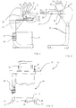
- a table 10 is shown equipped with a graphic output medium 12 and has a pivot bearing 14 for the graphic output medium.
- the graphic output medium is pivoted about the axis of the pivot bearing from an almost horizontal position to an almost upright position with an angle of 80 ° with respect to the horizontal.
- the pivot bearing 14 is attached below a work surface 16 of the table 10 and is mounted on the graphic output medium 12 in the vicinity of the front lower edge of the graphic output medium designed as a screen.
- an insert 22 is provided which a telescopic guide 24 for has a keyboard 26 and can be pulled out towards the front of the table 10. In the position shown in Fig. 1, however, the keyboard 26 is fully inserted.
- the graphic output medium 12 also has a device which detects the optical image information in a topographical-temporal relationship and is designed as a light gun 28.
- the light gun 28 In the position in Fig. 1, the light gun 28 is held in a receptacle 30 and at the same time protected with its sensor tip.
- the light gun 28 essentially has the shape of a pin 29 with a handle 31, a very flexible connecting cable 32 connecting the light gun 28 to the graphic output medium 12.
- the connecting cable 32 is preferably retractable spring-loaded.
- the light gun 28 has very high-resolution display optics, which is not shown here further, but is suitable for the acquisition of the optical image information of the graphic output medium in a topographical-temporal relationship.
- the graphic output medium 12 is connected together with the device in the form of the light gun 28 to a database system, which is not shown here and preferably has a computer 27 with decentralized intelligence.
- FIG. 2 shows the embodiment according to FIG. 1 in the lowered position of the graphic output medium.
- the keyboard 26 on the telescopic guide 24 is extended, so that manual input is also possible.
- the work surface 16 is still available.
- the storage of the graphic output medium 12 on the pivot bearing 14 is with a spring 34 and a damping device 35 equipped, which compensates for the weight of the graphic output medium 12 and enables easy pivoting.
- a release button 37 is provided concealed in a recessed grip underneath the work surface 16 in the vicinity of the front edge thereof. This trigger button 37 triggers a latching device which holds the graphic output medium 12 below against the action of the spring 34.
- a corresponding release button is located on the opposite side, also in the front area of the work surface 16 and also recessed.
- This trigger button acts on a foot 39 of the table 10, which is equipped with a bearing device 41.
- the bearing device 41 serves to adjust the height of the working surface 16 and the graphic output medium 12 and for this purpose also has a spring device and a damping device, not shown, which cooperate with a latching device in a corresponding manner, as previously described with regard to the pivot bearing 14.
- the two bearing devices 14 and 41 with the respective associated spring devices are dimensioned such that the respective weight force acting there is somewhat overcompensated.
- the spring characteristic of the spring device 34 is selected so that when the graphic output medium 12 is almost upright, the spring 34 is already strongly relaxed, so that the reduced weight force in this position is also just overcompensated.
- the characteristic curve of the spring of the bearing device 41 is chosen to be quite flat, so that almost the same spring force is exerted in the entire adjustment range.
- the light gun 28 is in the working position and can be brought to the corresponding areas of the image information by an operator, for example the doctor, in order to carry out the input.
- the light gun 28 is preferably to be held about 0.5 to 10 cm above the screen surface.
- the graphic output medium is shown in a substantially horizontal position, although it is also possible to carry out the input in a slightly inclined position.
- the positions of the graphic output medium that are most favorable for the input or rest position can preferably be snapped into place.
- the foot 39 spans a support surface 43 which corresponds approximately to the dimensions of the work surface 16.
- a vertical leg 45 is designed as a comparatively thick tube which merges into a horizontal rear leg 47.
- the rear leg 47 extends over the width of the table 10 and is bent forward at its end facing away from the leg 45, so that it ends in a side leg 49.
- a side leg 51 is stably attached at the transition point between the leg 45 and the rear leg 47, so that the bottom of the foot 39 has the shape of a U in plan view.
- each swivel castor 53 is pivotally mounted, which allows the table 10 to be easily moved towards the patient.
- a flat screen is provided which can also be brought into the completely horizontal position and at the same time serves in this position as a further extension of the work surface 16 to the rear.
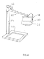
- FIG. 4 shows a further graphic output medium 36, which also has a device in the form of a light gun 38.
- the graphic output medium 36 can be locked in all positions and pivoted in any direction and for this purpose is mounted on a swivel arm 40, which in turn is rotatably mounted on a further swivel arm 42 about a vertical axis.
- the swivel arm 42 is either pivotally mounted on the wall or, as is shown in FIG. 4, a support 44 is provided on which the swivel arm 42 is rotatably mounted.
- the support 44 has a fairly solid base part 46 which is of sufficient weight that the graphic output medium 36 has a stable position in all positions of the swivel arms 40 and 42.
- the connecting cables for the graphic output medium 36 and the light gun 38 are passed through the bearing points of the swivel arms 40 and 42 and connected to a computer with a database system.
- This embodiment of the further graphical output medium is particularly suitable for parallel connection with the embodiment of the graphical output medium shown in FIGS. 1 to 3 and is preferably arranged in the treatment area of the attending doctor, so that, for example, the doctor can enter the necessary data while standing next to the treatment couch and, without the need for major mental steps, is even supported in the input.
- the graphical output medium 12 or the graphical output medium 36 can be moved on a somewhat smaller table, a decentralized computer recording the data input being installed in the table, the hard disk of which is brought into a secured position when the table is moved.
- the graphic output medium 12 can advantageously be designed as a screen, which is controlled in a predetermined time pattern.
- the light gun 28 then emits a positive feedback signal when the brightness value of the graphic output medium on the input surface exceeds a predetermined level.
- the graphic output medium is preferably high-resolution.
- the graphic output medium can also be designed as a plasma screen.
- the device capturing the optical image information of the graphic output medium in a topographical-time relationship is designed as a device capturing the optical image information in a topographical relationship, namely in the form of a touch panel.
- a pulse triggering device 55 is preferably provided on the light gun 28, with which the treating doctor clicks on an image area when the selection is to be made. According to the method according to the invention, it is also possible to click on number fields on the screen and thereby to enter a corresponding number or number.
- a worksheet can be attached to the free working surface 16, which works as a modular documentation sheet for a specific medical field. It is particularly favorable if the image information then corresponds to the worksheet information, so that an entry is possible in a very fail-safe manner.
Landscapes
- Engineering & Computer Science (AREA)
- Theoretical Computer Science (AREA)
- General Engineering & Computer Science (AREA)
- Human Computer Interaction (AREA)
- Physics & Mathematics (AREA)
- General Physics & Mathematics (AREA)
- Computer Hardware Design (AREA)
- Position Input By Displaying (AREA)
- Medicines That Contain Protein Lipid Enzymes And Other Medicines (AREA)
- Medical Treatment And Welfare Office Work (AREA)
Applications Claiming Priority (3)
| Application Number | Priority Date | Filing Date | Title |
|---|---|---|---|
| DE8903319U | 1989-05-02 | ||
| DE3914499A DE3914499A1 (de) | 1989-05-02 | 1989-05-02 | Verfahren zur eingabe von eingabedaten sowie verfahren zur zuordnung von neuen patientendaten zu vorhandenen daten sowie eingabesystem |
| DE3914499 | 1989-05-02 |
Publications (1)
| Publication Number | Publication Date |
|---|---|
| EP0400336A2 true EP0400336A2 (fr) | 1990-12-05 |
Family
ID=6379938
Family Applications (1)
| Application Number | Title | Priority Date | Filing Date |
|---|---|---|---|
| EP19900108145 Withdrawn EP0400336A2 (fr) | 1989-05-02 | 1990-04-28 | Appareil d'entrée/de sortie d'informations, en particulier de données de patients |
Country Status (4)
| Country | Link |
|---|---|
| EP (1) | EP0400336A2 (fr) |
| JP (1) | JPH03206519A (fr) |
| CA (1) | CA2015825A1 (fr) |
| DE (1) | DE3914499A1 (fr) |
Cited By (2)
| Publication number | Priority date | Publication date | Assignee | Title |
|---|---|---|---|---|
| EP0542442A1 (fr) * | 1991-10-24 | 1993-05-19 | Critikon, Inc. | Unité de surveillance de patient et station pour donner des soins |
| US9389643B1 (en) | 1998-09-18 | 2016-07-12 | Intermetro Industries Corporation | Mobile computer workstation |
Families Citing this family (1)
| Publication number | Priority date | Publication date | Assignee | Title |
|---|---|---|---|---|
| DE4214143A1 (de) * | 1992-04-29 | 1993-11-04 | Avm Schmelter Gmbh & Co Kg | Anordnung zur dezentralen datenaufnahme in krankenhaeusern |
-
1989
- 1989-05-02 DE DE3914499A patent/DE3914499A1/de not_active Withdrawn
-
1990
- 1990-04-28 EP EP19900108145 patent/EP0400336A2/fr not_active Withdrawn
- 1990-05-01 CA CA002015825A patent/CA2015825A1/fr not_active Abandoned
- 1990-05-02 JP JP2115370A patent/JPH03206519A/ja active Pending
Cited By (2)
| Publication number | Priority date | Publication date | Assignee | Title |
|---|---|---|---|---|
| EP0542442A1 (fr) * | 1991-10-24 | 1993-05-19 | Critikon, Inc. | Unité de surveillance de patient et station pour donner des soins |
| US9389643B1 (en) | 1998-09-18 | 2016-07-12 | Intermetro Industries Corporation | Mobile computer workstation |
Also Published As
| Publication number | Publication date |
|---|---|
| JPH03206519A (ja) | 1991-09-09 |
| DE3914499A1 (de) | 1990-11-08 |
| CA2015825A1 (fr) | 1990-11-02 |
Similar Documents
| Publication | Publication Date | Title |
|---|---|---|
| DE69621540T2 (de) | Elektronenmikroskop | |
| DE19700582A1 (de) | Tisch mit Hubplatte, Hubtisch sowie Kombination hieraus | |
| DE4033010C2 (de) | Möbelelement für einen Bildschirm-Arbeitsplatz | |
| DE102009048361A1 (de) | Medizinische Therapieeinrichtung | |
| DE102006018537B4 (de) | Steuerkonsole an einer Armlehne eines Fahrzeugsitzes | |
| DE102017120792A1 (de) | Landwirtschaftliche Arbeitsmaschine | |
| DE19845027C2 (de) | Medizintechnisches System | |
| DE4224246C1 (en) | Manual control knob for diagnostic X=ray appts. - has three switches mounted in control knob to adjust aperture stop plates, X=ray tube alignment patient table and spacing between tube and detector | |
| DE4341324A1 (de) | Medizinische Anlage mit Mitteln zum Erfassen einer physiologischen Funktion | |
| DE102015209024B4 (de) | Bildschirmlesegerät | |
| EP0400336A2 (fr) | Appareil d'entrée/de sortie d'informations, en particulier de données de patients | |
| DE102010014216A1 (de) | Präsentationssystem | |
| DE2451618C3 (de) | Zahnärztliches Lehr- und Übungsgerät | |
| DE102015209020B4 (de) | Bildschirmlesegerät | |
| EP0444260A2 (fr) | Dispositif pour déterminer les réactions du téléspectateur à un spot publicitaire vidéo | |
| DE4341291A1 (de) | Medizinische Anlage mit einer Bedieneinrichtung | |
| DE60114087T2 (de) | Stuhl mit einer Steuerungseinrichtung | |
| DE102019108670B4 (de) | Verfahren zur Steuerung eines Geräts, insbesondere einer Handprothese oder eines Roboterarms, sowie Anordnung zur Durchführung des Verfahrens | |
| DE8710445U1 (de) | Kombinationstisch | |
| DE3418319C2 (fr) | ||
| AT397619B (de) | Übungsgerät zum trainieren der menschlichen arm- und oberkörpermuskulatur | |
| DE102018108855B4 (de) | Positionierungsvorrichtung, Anzeigeanordnung und Verfahren zur automatischen Positionierung einer Anzeigevorrichtung | |
| DE69031221T2 (de) | Tastatur | |
| WO2004055572A1 (fr) | Satellite de commande pour des systemes optiques | |
| DE102020114426A1 (de) | Gerätesteuerung |
Legal Events
| Date | Code | Title | Description |
|---|---|---|---|
| PUAI | Public reference made under article 153(3) epc to a published international application that has entered the european phase |
Free format text: ORIGINAL CODE: 0009012 |
|
| AK | Designated contracting states |
Kind code of ref document: A2 Designated state(s): AT BE CH DE DK ES FR GB IT LI NL SE |
|
| RAP1 | Party data changed (applicant data changed or rights of an application transferred) |
Owner name: DRESDNER BANK AG FILIALE AACHEN |
|
| RIN1 | Information on inventor provided before grant (corrected) |
Inventor name: WERDIER, DIETER |
|
| RAP1 | Party data changed (applicant data changed or rights of an application transferred) |
Owner name: WERDIER, DIETER, DR. |
|
| RIN1 | Information on inventor provided before grant (corrected) |
Inventor name: WERDIER, DIETER, DR. |
|
| STAA | Information on the status of an ep patent application or granted ep patent |
Free format text: STATUS: THE APPLICATION IS DEEMED TO BE WITHDRAWN |
|
| 18D | Application deemed to be withdrawn |
Effective date: 19921105 |