EP0400476A2 - Dispositif pour l'usinage à laser - Google Patents
Dispositif pour l'usinage à laser Download PDFInfo
- Publication number
- EP0400476A2 EP0400476A2 EP90109821A EP90109821A EP0400476A2 EP 0400476 A2 EP0400476 A2 EP 0400476A2 EP 90109821 A EP90109821 A EP 90109821A EP 90109821 A EP90109821 A EP 90109821A EP 0400476 A2 EP0400476 A2 EP 0400476A2
- Authority
- EP
- European Patent Office
- Prior art keywords
- movement
- workpiece
- transport
- speed
- machining
- Prior art date
- Legal status (The legal status is an assumption and is not a legal conclusion. Google has not performed a legal analysis and makes no representation as to the accuracy of the status listed.)
- Granted
Links
- 238000003754 machining Methods 0.000 title claims description 39
- 238000002372 labelling Methods 0.000 claims description 3
- 230000006978 adaptation Effects 0.000 description 5
- 238000002360 preparation method Methods 0.000 description 2
- 230000001133 acceleration Effects 0.000 description 1
- 230000003287 optical effect Effects 0.000 description 1
- 230000002093 peripheral effect Effects 0.000 description 1
Images

Classifications
-
- B—PERFORMING OPERATIONS; TRANSPORTING
- B23—MACHINE TOOLS; METAL-WORKING NOT OTHERWISE PROVIDED FOR
- B23K—SOLDERING OR UNSOLDERING; WELDING; CLADDING OR PLATING BY SOLDERING OR WELDING; CUTTING BY APPLYING HEAT LOCALLY, e.g. FLAME CUTTING; WORKING BY LASER BEAM
- B23K26/00—Working by laser beam, e.g. welding, cutting or boring
- B23K26/08—Devices involving relative movement between laser beam and workpiece
- B23K26/083—Devices involving movement of the workpiece in at least one axial direction
- B23K26/0838—Devices involving movement of the workpiece in at least one axial direction by using an endless conveyor belt
-
- B—PERFORMING OPERATIONS; TRANSPORTING
- B23—MACHINE TOOLS; METAL-WORKING NOT OTHERWISE PROVIDED FOR
- B23K—SOLDERING OR UNSOLDERING; WELDING; CLADDING OR PLATING BY SOLDERING OR WELDING; CUTTING BY APPLYING HEAT LOCALLY, e.g. FLAME CUTTING; WORKING BY LASER BEAM
- B23K2101/00—Articles made by soldering, welding or cutting
- B23K2101/007—Marks, e.g. trade marks
Definitions
- the invention relates to a laser processing device, in particular for labeling workpieces, which are guided almost continuously along the processing plane.
- the respective workpiece is preferably fixedly positioned in the processing plane in such a way that it comes to lie as centrally as possible in the available image field of the processing device.
- the laser beam for carrying out the respective processing can be guided freely within this image field.
- the size of the image field can be set by the distance of the processing device from the processing plane or by the focusing optics at the output of the laser generator. In order to generate a high-energy and sharply focused laser beam, it is advantageous to choose the image field as small as possible.
- the image field it is necessary for the image field to have a minimum extent so that the laser beam can be guided to all desired machining locations. If such a compromise between the quality of the laser beam and the necessary size of the image field is not possible, it may be necessary to carry out a machining process in sections and to reposition the workpiece in between.
- the invention is based on the object of specifying a laser machining device to which the workpieces are fed almost continuously with a movement speed that is as constant as possible in the machining plane.
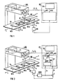
- the laser processing device LBG contains a generator LG for generating the laser beam LS.
- Means for guiding the beam on the processing plane BE are also included. These are shown by way of example in FIG. 1 in the form of at least one controllable mirror SP.
- this deflects the laser beam LS generated by the generator LG through the focusing optics FO onto the processing plane BE.
- this enables the focal point FS of the laser beam to be guided within the maximum available image field BF on the processing plane BE.
- the beam guidance by means of positioning signals S x , S y , which are formed by a processing control BS from the data BSD associated with the respectively desired processing or labeling for laser beam guidance.
- the processing control BS preferably contains a data preparation DA for forming the beam guidance data BSD from input variables, and an adaptation unit APE for outputting the data to the beam guidance means, ie in particular at least to the mirror SP.
- the workpieces to be machined are guided almost continuously along the machining plane.
- a conveyor belt TB serves as an example in FIG.
- the workpieces WS1 ... WS4 are guided in the (-x) direction in the machining plane BE with an almost constant speed of movement v.
- the workpiece WS3 is located almost in the center of the image field BF below the focusing optics FO.
- the beam guidance data BSD are, according to the innovation, adapted to the speed of movement v of the workpieces in the processing plane, and are then preferably output to the beam guidance means in the form of the positioning signals S x , S y .
- the adaptation is preferably carried out by the adaptation unit APE within the processing control BS.
- the actual value of the speed of movement v of the workpieces is preferably detected via a measuring transducer MG and fed to the adaptation unit APE.
- the entire available image field BF no longer has to be used when guiding the laser beam on the machining plane. If, according to a first embodiment of the invention, the movement speed v of the workpieces is almost completely compensated for by appropriate adaptation of the beam guidance data, the beam hardly needs to be guided to the edges of the image field BF at which a workpiece enters or leaves the image field.
- the workpieces are guided, for example, in the (-x) coordinate direction in the processing plane BE, the workpieces enter the image field BF in the edge region R1 and exit the latter in the edge region R2.
- the focal point FS is thus only guided in the ( ⁇ y) coordinate direction under certain circumstances up to the image field boundary, while it is increasingly located in the center of the image field BF in the ( ⁇ x) direction and is no longer guided into the edge regions R1, R2. This fact can be used according to further embodiments of the invention.
- the overall image field can be selected smaller, e.g. by adjusting the focusing optics FO. This improves the focusability of the laser beam, so that e.g. a greater energy density is available at the focal point FS for workpiece machining.
- edge regions R1, R2 of the image field BF which are increasingly not used due to the narrowing of the image field in the ( ⁇ x) direction, are nevertheless used by corresponding specification of the beam guidance data BSD, this has an increase in the ( ⁇ x) direction in FIG. 1 of the usable processing field in the processing plane BE. Larger workpiece areas can thus be machined in one operation.
- the machining process of one of the workpieces which is guided almost continuously along the machining plane is started approximately in the edge region of the image field BF at which the workpiece enters the image field.
- this is the edge region R1.
- the speed of movement v of the workpieces can now be matched to the average time required for a machining operation such that the machining is completed when the machined workpiece or the workpiece area emerges from the image field BF at the corresponding edge area.
- this is, for example, the edge area R2. This makes it possible to further increase the speed of movement v of the workpieces and thus the overall throughput of the laser processing device.
- the excessive movement speed v is therefore no longer compensated for by the advancing movement of the focal point FS in the machining direction.
- the focus point thus gradually moves during the processing operation from the one image field edge area in which the processing operation was started to the opposite image field edge area in which the processing operation is ended.
- the workpieces WS1 ... WS4 enter the image field BF in the edge region R1.
- the focal point FS is now positioned in such a way that when a workpiece enters the image field, its processing is started in this edge area. Since the speed v of the workpieces in the (-x) direction is greater than the maximum possible machining speed in the (+ x) direction, the focal point is gradually "taken along" to the opposite edge region R2 during the machining.
- the movement speed v and the average duration of a machining process are coordinated with one another in such a way that the machining process is completed when this edge region R2 is reached.
- the dead time until the start of the next machining process which is particularly advantageous e.g. can be adjusted by the distance of the workpieces WS1 ... WS4 on the conveyor belt TB, is used to reposition the laser beam on the starting point, which in turn is located in the peripheral area R1, for the subsequent machining process.
- movement means are present which enable movement of at least a part of the laser machining device during a machining process in the direction of the movement of the workpieces.
- the laser processing device LBG contains a fixed part FT, which contains, for example, the generator LG for generating the laser beam LS. Furthermore, there is a movable part BT which contains the means for beam guidance, in particular the at least one mirror SP.
- the movable part BT can preferably be moved parallel to the ( ⁇ x) movement direction of the workpieces by means of hanging rails HS.
- An optical light guide LL is preferably used to transmit the laser beam between the fixed and the movable part.
- the processing device specifies the beam guidance data adapted to the relative speed between the workpieces in the processing plane and the beam guidance means in the movable part BT.
- the movable part BT of the laser machining device is tracked at a lower speed in the direction of the workpiece movement for the duration of a machining operation.
- the dead times between individual machining processes are also used here in order to return the movable part BT of the machining device to the starting position.
- both the movable part of the processing device and the focal point FS are particularly advantageously carried along from one edge region to the opposite edge region of the image field BF in the manner already described with reference to FIG. 1.
- the mean value v M of the speed of movement v of the workpieces in the machining plane BE is determined via a transmitter MWB.
- the beam guidance data BSD which are preferably formed by a data preparation DA from default values, are adapted to the mean value v M.
- the beam guidance data BSD 'corrected in this way are further fed to a modulator MD, which in turn adapts them to the deviation ⁇ v of the actual value v of the speed of movement of the workpieces from the associated mean value V M.
- the beam guidance data BSD ⁇ corrected in this way are finally preferably output in the form of positioning signals S x , S y to the beam guidance means in the laser processing device.
Landscapes
- Physics & Mathematics (AREA)
- Optics & Photonics (AREA)
- Engineering & Computer Science (AREA)
- Plasma & Fusion (AREA)
- Mechanical Engineering (AREA)
- Laser Beam Processing (AREA)
Applications Claiming Priority (2)
| Application Number | Priority Date | Filing Date | Title |
|---|---|---|---|
| DE8906578U | 1989-05-29 | ||
| DE8906578U DE8906578U1 (de) | 1989-05-29 | 1989-05-29 | Laserbearbeitungsvorrichtung |
Publications (4)
| Publication Number | Publication Date |
|---|---|
| EP0400476A2 true EP0400476A2 (fr) | 1990-12-05 |
| EP0400476A3 EP0400476A3 (fr) | 1991-02-06 |
| EP0400476B1 EP0400476B1 (fr) | 1993-03-31 |
| EP0400476B2 EP0400476B2 (fr) | 1998-08-12 |
Family
ID=6839628
Family Applications (1)
| Application Number | Title | Priority Date | Filing Date |
|---|---|---|---|
| EP90109821A Expired - Lifetime EP0400476B2 (fr) | 1989-05-29 | 1990-05-23 | Procédé pour l'usinage à laser |
Country Status (2)
| Country | Link |
|---|---|
| EP (1) | EP0400476B2 (fr) |
| DE (2) | DE8906578U1 (fr) |
Cited By (15)
| Publication number | Priority date | Publication date | Assignee | Title |
|---|---|---|---|---|
| EP0495647A1 (fr) * | 1991-01-17 | 1992-07-22 | United Distillers Plc | Marquage dynamique au laser |
| GB2252068B (en) * | 1991-01-17 | 1994-05-04 | United Distillers Plc | Dynamic laser marking |
| US5698119A (en) * | 1994-12-16 | 1997-12-16 | Alza Corporation | Apparatus for forming dispenser delivery ports |
| US6130402A (en) * | 1996-04-26 | 2000-10-10 | Servicio Industrial De Marcaje Y Codification, S.A. | System and process for marking or perforating |
| EP1452263A1 (fr) * | 2003-02-27 | 2004-09-01 | Osmotica Corp. | Système et méthode de perçage par laser |
| US6791592B2 (en) | 2000-04-18 | 2004-09-14 | Laserink | Printing a code on a product |
| US7046267B2 (en) | 2003-12-19 | 2006-05-16 | Markem Corporation | Striping and clipping correction |
| DE102006036544A1 (de) * | 2006-08-04 | 2008-02-07 | Patent-Treuhand-Gesellschaft für elektrische Glühlampen mbH | Optoelektronisches Modul |
| US7394479B2 (en) | 2005-03-02 | 2008-07-01 | Marken Corporation | Pulsed laser printing |
| CN102470483A (zh) * | 2009-08-03 | 2012-05-23 | 东丽工程株式会社 | 标记装置及其方法 |
| RU2478588C2 (ru) * | 2006-10-18 | 2013-04-10 | Тиама | Способ и установка для маркировки прозрачных или полупрозрачных объектов при высокой температуре |
| WO2016083909A1 (fr) * | 2014-11-27 | 2016-06-02 | Progetto Futuro S.R.L. | Station pour traiter les surfaces de produits céramiques, poinçons, filières et procédé de traitement |
| EP2374569B1 (fr) | 2010-03-15 | 2018-11-07 | Ewag AG | Dispositif de traitement au laser et procédé de fabrication d'un outil à rotation symétrique |
| EP2314412B1 (fr) | 2009-10-22 | 2018-12-19 | Ewag AG | Dispositif de traitement au laser et procédé de fabrication d'une surface sur une ébauche |
| US10583668B2 (en) | 2018-08-07 | 2020-03-10 | Markem-Imaje Corporation | Symbol grouping and striping for wide field matrix laser marking |
Families Citing this family (2)
| Publication number | Priority date | Publication date | Assignee | Title |
|---|---|---|---|---|
| DE102023114685A1 (de) * | 2023-06-05 | 2024-12-05 | Krones Aktiengesellschaft | Verfahren und Vorrichtung zum Lasermarkieren von Behältern |
| DE102023114686A1 (de) * | 2023-06-05 | 2024-12-05 | Krones Aktiengesellschaft | Vorrichtung und Verfahren zum Lasermarkieren von Behältern |
Family Cites Families (4)
| Publication number | Priority date | Publication date | Assignee | Title |
|---|---|---|---|---|
| US4049945A (en) * | 1973-10-10 | 1977-09-20 | Winkler & Dunnebier Maschinenfabrik Und Eisengiesserei Kg | Method of and apparatus for cutting material to shape from a moving web by burning |
| US4297559A (en) * | 1979-05-10 | 1981-10-27 | Olin Corporation | Apparatus for controlled perforation of moving webs with fixed focus laser beam |
| AT389850B (de) * | 1985-09-06 | 1990-02-12 | Walter Sticht | Druck- und beschriftungsverfahren fuer bauteile |
| DD243798A1 (de) * | 1985-10-17 | 1987-03-11 | Erfurt Mikroelektronik | Verfahren zum kennzeichnen von kleinen gegenstaenden, insbesondere von elektronischen bauelementen |
-
1989
- 1989-05-29 DE DE8906578U patent/DE8906578U1/de not_active Expired - Lifetime
-
1990
- 1990-05-23 EP EP90109821A patent/EP0400476B2/fr not_active Expired - Lifetime
- 1990-05-23 DE DE9090109821T patent/DE59001100D1/de not_active Expired - Fee Related
Cited By (25)
| Publication number | Priority date | Publication date | Assignee | Title |
|---|---|---|---|---|
| WO1992012820A1 (fr) * | 1991-01-17 | 1992-08-06 | United Distillers Plc | Marquage au laser dynamique |
| GB2252068B (en) * | 1991-01-17 | 1994-05-04 | United Distillers Plc | Dynamic laser marking |
| AU659131B2 (en) * | 1991-01-17 | 1995-05-11 | United Distillers Plc | Dynamic laser marking |
| US5653900A (en) * | 1991-01-17 | 1997-08-05 | United Distillers Plc | Dynamic laser marking |
| EP0495647A1 (fr) * | 1991-01-17 | 1992-07-22 | United Distillers Plc | Marquage dynamique au laser |
| US5698119A (en) * | 1994-12-16 | 1997-12-16 | Alza Corporation | Apparatus for forming dispenser delivery ports |
| US6130402A (en) * | 1996-04-26 | 2000-10-10 | Servicio Industrial De Marcaje Y Codification, S.A. | System and process for marking or perforating |
| US7167194B2 (en) | 2000-04-18 | 2007-01-23 | Laserink | Printing a code on a product |
| US6791592B2 (en) | 2000-04-18 | 2004-09-14 | Laserink | Printing a code on a product |
| US6829000B2 (en) | 2000-04-18 | 2004-12-07 | Laserink | Printing a code on a product |
| EP1764180A1 (fr) * | 2003-02-27 | 2007-03-21 | Osmotica Corp. | Système et procédé de perçage au laser |
| EP1452263A1 (fr) * | 2003-02-27 | 2004-09-01 | Osmotica Corp. | Système et méthode de perçage par laser |
| US7046267B2 (en) | 2003-12-19 | 2006-05-16 | Markem Corporation | Striping and clipping correction |
| US7394479B2 (en) | 2005-03-02 | 2008-07-01 | Marken Corporation | Pulsed laser printing |
| DE102006036544A1 (de) * | 2006-08-04 | 2008-02-07 | Patent-Treuhand-Gesellschaft für elektrische Glühlampen mbH | Optoelektronisches Modul |
| US7789573B2 (en) | 2006-08-04 | 2010-09-07 | Osram Gesellschaft Mit Beschrankter Haftung | Optoelectronic module |
| RU2478588C2 (ru) * | 2006-10-18 | 2013-04-10 | Тиама | Способ и установка для маркировки прозрачных или полупрозрачных объектов при высокой температуре |
| RU2634130C2 (ru) * | 2006-10-18 | 2017-10-24 | Тиама | Способ и установка для маркировки прозрачных или полупрозрачных объектов при высокой температуре |
| CN102470483A (zh) * | 2009-08-03 | 2012-05-23 | 东丽工程株式会社 | 标记装置及其方法 |
| TWI454687B (zh) * | 2009-08-03 | 2014-10-01 | Toray Eng Co Ltd | Marking device and method |
| CN102470483B (zh) * | 2009-08-03 | 2015-04-01 | 东丽工程株式会社 | 标记装置及其方法 |
| EP2314412B1 (fr) | 2009-10-22 | 2018-12-19 | Ewag AG | Dispositif de traitement au laser et procédé de fabrication d'une surface sur une ébauche |
| EP2374569B1 (fr) | 2010-03-15 | 2018-11-07 | Ewag AG | Dispositif de traitement au laser et procédé de fabrication d'un outil à rotation symétrique |
| WO2016083909A1 (fr) * | 2014-11-27 | 2016-06-02 | Progetto Futuro S.R.L. | Station pour traiter les surfaces de produits céramiques, poinçons, filières et procédé de traitement |
| US10583668B2 (en) | 2018-08-07 | 2020-03-10 | Markem-Imaje Corporation | Symbol grouping and striping for wide field matrix laser marking |
Also Published As
| Publication number | Publication date |
|---|---|
| EP0400476B2 (fr) | 1998-08-12 |
| DE8906578U1 (de) | 1990-09-27 |
| EP0400476B1 (fr) | 1993-03-31 |
| DE59001100D1 (de) | 1993-05-06 |
| EP0400476A3 (fr) | 1991-02-06 |
Similar Documents
| Publication | Publication Date | Title |
|---|---|---|
| EP0400476B1 (fr) | Dispositif pour l'usinage à laser | |
| DE69602525T2 (de) | Mehrgeschwindigkeitspositioniersystem mit verbessertem profilierfilter | |
| DE10000469C2 (de) | Verfahren zum fortlaufenden Ablängen von Zuschnitten aus einem kontinuierlich bewegten Endlosmaterial und zugehörige Vorrichtung | |
| EP0343661B1 (fr) | Procédé et dispositif de fabrication de pièces poinçonnées soudées | |
| DE2725959C3 (de) | Elektronenstrahl-Bearbeitungseinrichtung | |
| DE102015202347A1 (de) | Bestrahlungseinrichtung, Bearbeitungsmaschine und Verfahren zum Herstellen einer Schicht eines dreidimensionalen Bauteils | |
| EP0329787A1 (fr) | Procede et dispositif de traitement laser d'un objet | |
| DE3787170T2 (de) | Gewindekontrollvorrichtung. | |
| EP0166351A2 (fr) | Dispositif pour une machine de travail de déformation des tôles | |
| EP3345713A1 (fr) | Procédé et dispositif d'ajustement de formation de jet et d'orientation de jet orientés processus | |
| DE19700853A1 (de) | Numerisches Regelgerät und Verfahren zum Regeln der Beschleunigung/Verzögerung eines Spindelmotors des numerischen Regelgerätes | |
| EP0653791A1 (fr) | Dispositif pour l'inscription de pièces d'ouvrage | |
| DE69628813T2 (de) | Laserbearbeitungsvorrichtung und laserbearbeitungsverfahren | |
| DE3546130A1 (de) | Verfahren zur steuerung der bearbeitung in einer elektroerosionsmaschine mit einer drahtelektrode | |
| DE2910399A1 (de) | Schaltungsanordnung fuer eine automatisierte pressenanordnung | |
| DE3941057C2 (de) | Verfahren und Vorrichtung zur Konturbearbeitung eines Werkstücks | |
| DE102018125436A1 (de) | Verfahren zur materialabtragenden Laserbearbeitung eines Werkstücks | |
| EP0482240A1 (fr) | Procédé pour le façonnage précis de pièces à usiner plates ou légèrement courbées | |
| DE4335830A1 (de) | Drahtschneidemaschine mit elektrischer Entladung und zugehöriges Verfahren | |
| DE4412093A1 (de) | Verfahren und Vorrichtung zur Steuerung einer Laserschweißmaschine | |
| DE2401424A1 (de) | Vorrichtung zum funkenerosiven schneiden von sich erweiternden durchbruechen in metallischen werkstuecken | |
| DE2703115C2 (de) | Lichtsetzmaschine und Verfahren zum Betreiben derselben | |
| EP0503509B1 (fr) | Méthode de coupe par fil électro-érosif | |
| EP0998370A1 (fr) | Procede et dispositif pour la production d'une matrice | |
| DE60111266T2 (de) | Verfahren in einem blechbearbeitungszentrum und blechbearbeitungszentrum |
Legal Events
| Date | Code | Title | Description |
|---|---|---|---|
| PUAI | Public reference made under article 153(3) epc to a published international application that has entered the european phase |
Free format text: ORIGINAL CODE: 0009012 |
|
| AK | Designated contracting states |
Kind code of ref document: A2 Designated state(s): CH DE FR IT LI |
|
| PUAL | Search report despatched |
Free format text: ORIGINAL CODE: 0009013 |
|
| 17P | Request for examination filed |
Effective date: 19901205 |
|
| AK | Designated contracting states |
Kind code of ref document: A3 Designated state(s): CH DE FR IT LI |
|
| 17Q | First examination report despatched |
Effective date: 19920226 |
|
| GRAA | (expected) grant |
Free format text: ORIGINAL CODE: 0009210 |
|
| AK | Designated contracting states |
Kind code of ref document: B1 Designated state(s): CH DE FR IT LI |
|
| REF | Corresponds to: |
Ref document number: 59001100 Country of ref document: DE Date of ref document: 19930506 |
|
| ET | Fr: translation filed | ||
| ITF | It: translation for a ep patent filed | ||
| PLBI | Opposition filed |
Free format text: ORIGINAL CODE: 0009260 |
|
| 26 | Opposition filed |
Opponent name: UNITED DISTILLERS PLC. Effective date: 19931223 |
|
| RAP2 | Party data changed (patent owner data changed or rights of a patent transferred) |
Owner name: ROFIN SINAR LASER GMBH |
|
| APAE | Appeal reference modified |
Free format text: ORIGINAL CODE: EPIDOS REFNO |
|
| APAC | Appeal dossier modified |
Free format text: ORIGINAL CODE: EPIDOS NOAPO |
|
| PLAW | Interlocutory decision in opposition |
Free format text: ORIGINAL CODE: EPIDOS IDOP |
|
| RTI2 | Title (correction) |
Free format text: LASER MACHINING METHOD |
|
| PUAH | Patent maintained in amended form |
Free format text: ORIGINAL CODE: 0009272 |
|
| STAA | Information on the status of an ep patent application or granted ep patent |
Free format text: STATUS: PATENT MAINTAINED AS AMENDED |
|
| REG | Reference to a national code |
Ref country code: CH Ref legal event code: PUE Owner name: SIEMENS AKTIENGESELLSCHAFT TRANSFER- ROFIN-SINAR L Ref country code: CH Ref legal event code: NV Representative=s name: E. BLUM & CO. PATENTANWAELTE |
|
| 27A | Patent maintained in amended form |
Effective date: 19980812 |
|
| AK | Designated contracting states |
Kind code of ref document: B2 Designated state(s): CH DE FR IT LI |
|
| REG | Reference to a national code |
Ref country code: CH Ref legal event code: AEN Free format text: AUFRECHTERHALTUNG DES PATENTES IN GEAENDERTER FORM |
|
| ET3 | Fr: translation filed ** decision concerning opposition | ||
| APAH | Appeal reference modified |
Free format text: ORIGINAL CODE: EPIDOSCREFNO |
|
| PGFP | Annual fee paid to national office [announced via postgrant information from national office to epo] |
Ref country code: FR Payment date: 20060519 Year of fee payment: 17 |
|
| PGFP | Annual fee paid to national office [announced via postgrant information from national office to epo] |
Ref country code: CH Payment date: 20060524 Year of fee payment: 17 |
|
| PGFP | Annual fee paid to national office [announced via postgrant information from national office to epo] |
Ref country code: IT Payment date: 20060531 Year of fee payment: 17 |
|
| PGFP | Annual fee paid to national office [announced via postgrant information from national office to epo] |
Ref country code: DE Payment date: 20060725 Year of fee payment: 17 |
|
| REG | Reference to a national code |
Ref country code: CH Ref legal event code: PFA Owner name: ROFIN-SINAR LASER GMBH Free format text: ROFIN-SINAR LASER GMBH#BERZELIUSSTRASSE 87#22113 HAMBURG (DE) -TRANSFER TO- ROFIN-SINAR LASER GMBH#BERZELIUSSTRASSE 87#22113 HAMBURG (DE) |
|
| REG | Reference to a national code |
Ref country code: CH Ref legal event code: PL |
|
| PG25 | Lapsed in a contracting state [announced via postgrant information from national office to epo] |
Ref country code: LI Free format text: LAPSE BECAUSE OF NON-PAYMENT OF DUE FEES Effective date: 20070531 Ref country code: CH Free format text: LAPSE BECAUSE OF NON-PAYMENT OF DUE FEES Effective date: 20070531 |
|
| REG | Reference to a national code |
Ref country code: FR Ref legal event code: ST Effective date: 20080131 |
|
| PG25 | Lapsed in a contracting state [announced via postgrant information from national office to epo] |
Ref country code: DE Free format text: LAPSE BECAUSE OF NON-PAYMENT OF DUE FEES Effective date: 20071201 |
|
| PG25 | Lapsed in a contracting state [announced via postgrant information from national office to epo] |
Ref country code: FR Free format text: LAPSE BECAUSE OF NON-PAYMENT OF DUE FEES Effective date: 20070531 |
|
| PG25 | Lapsed in a contracting state [announced via postgrant information from national office to epo] |
Ref country code: IT Free format text: LAPSE BECAUSE OF NON-PAYMENT OF DUE FEES Effective date: 20070523 |