EP0400516A1 - Machine vibrante, en particulier pour le séchage en masse de pièces métalliques, à déchargement automatique des pièces séchées - Google Patents
Machine vibrante, en particulier pour le séchage en masse de pièces métalliques, à déchargement automatique des pièces séchées Download PDFInfo
- Publication number
- EP0400516A1 EP0400516A1 EP90110047A EP90110047A EP0400516A1 EP 0400516 A1 EP0400516 A1 EP 0400516A1 EP 90110047 A EP90110047 A EP 90110047A EP 90110047 A EP90110047 A EP 90110047A EP 0400516 A1 EP0400516 A1 EP 0400516A1
- Authority
- EP
- European Patent Office
- Prior art keywords
- wing
- unloading
- vibrating machine
- tank body
- dried parts
- Prior art date
- Legal status (The legal status is an assumption and is not a legal conclusion. Google has not performed a legal analysis and makes no representation as to the accuracy of the status listed.)
- Granted
Links
- 238000001035 drying Methods 0.000 title claims abstract description 11
- 230000004888 barrier function Effects 0.000 claims description 2
- 238000000034 method Methods 0.000 description 3
- 230000008878 coupling Effects 0.000 description 2
- 238000010168 coupling process Methods 0.000 description 2
- 238000005859 coupling reaction Methods 0.000 description 2
- 230000008569 process Effects 0.000 description 2
- 230000002860 competitive effect Effects 0.000 description 1
- 238000005485 electric heating Methods 0.000 description 1
- 238000010438 heat treatment Methods 0.000 description 1
- 230000000670 limiting effect Effects 0.000 description 1
- 230000004048 modification Effects 0.000 description 1
- 238000012986 modification Methods 0.000 description 1
- 238000005498 polishing Methods 0.000 description 1
- 238000004064 recycling Methods 0.000 description 1
- 230000000284 resting effect Effects 0.000 description 1
- 230000000717 retained effect Effects 0.000 description 1
- 238000000926 separation method Methods 0.000 description 1
Images
Classifications
-
- B—PERFORMING OPERATIONS; TRANSPORTING
- B24—GRINDING; POLISHING
- B24B—MACHINES, DEVICES, OR PROCESSES FOR GRINDING OR POLISHING; DRESSING OR CONDITIONING OF ABRADING SURFACES; FEEDING OF GRINDING, POLISHING, OR LAPPING AGENTS
- B24B31/00—Machines or devices designed for polishing or abrading surfaces on work by means of tumbling apparatus or other apparatus in which the work and/or the abrasive material is loose; Accessories therefor
- B24B31/12—Accessories; Protective equipment or safety devices; Installations for exhaustion of dust or for sound absorption specially adapted for machines covered by group B24B31/00
- B24B31/16—Means for separating the workpiece from the abrasive medium at the end of operation
-
- F—MECHANICAL ENGINEERING; LIGHTING; HEATING; WEAPONS; BLASTING
- F26—DRYING
- F26B—DRYING SOLID MATERIALS OR OBJECTS BY REMOVING LIQUID THEREFROM
- F26B17/00—Machines or apparatus for drying materials in loose, plastic, or fluidised form, e.g. granules, staple fibres, with progressive movement
- F26B17/26—Machines or apparatus for drying materials in loose, plastic, or fluidised form, e.g. granules, staple fibres, with progressive movement with movement performed by reciprocating or oscillating conveyors propelling materials over stationary surfaces; with movement performed by reciprocating or oscillating shelves, sieves, or trays
- F26B17/266—Machines or apparatus for drying materials in loose, plastic, or fluidised form, e.g. granules, staple fibres, with progressive movement with movement performed by reciprocating or oscillating conveyors propelling materials over stationary surfaces; with movement performed by reciprocating or oscillating shelves, sieves, or trays the materials to be dried being moved in a helical, spiral or circular path, e.g. vibrated helix
Definitions
- the present invention relates to a vibrating machine, particularly for the mass drying of metallic bodies, with automatic unloading of the dried parts.
- vibrating machines are currently commercially available which are predominantly used for drying metallic parts and comprise a tank body provided with vibrating means and associated with a supporting frame through the interposition of anti-vibration means.
- a circular bottom is provided inside the tank body and has a ramp-like portion which conveys the items being processed together with the loose material, which can be constituted by abrasive elements, polishing elements and drying elements, to a selection plane which has an initial fixed portion, which in practice separates the parts being processed from the loose material, and an openable central portion which can be connected to a terminal unloading portion.
- the openable central portion is in practice constituted by a grid which is pivoted, at the edge which is contiguous to the terminal portion to be moved, to a raised position which allows the parts being processed to fall inside the tank.
- the central portion or grid is arranged so as to continue the fixed initial portion, consequently conveying the parts outward.
- the aim of the invention is to solve the above described problem by providing a vibrating machine particularly for the mass drying of metallic bodies which allows the unloading steps to be carried out automatically, since the presence of the operator is not required even in the step of passage from the operative condition with recycling to the unloading condition.
- a particular object of the invention is to provide a vibrating machine which allows to move the openable central portion without running the risk in any way of clamping or trapping parts being processed, during the various operative steps of passage from one working condition to another.
- Another object of the present invention is to provide a vibrating machine which achieves said automation with extremely simple means which are easy to use.
- Not least object of the present invention is to provide a vibrating machine which can be easily obtained starting from commonly commercially available elements and materials and which is furthermore competitive from a merely economical point of view.
- a vibrating machine particularly for the mass drying of metallic bodies, with automatic unloading of the dried parts
- a vibrating machine which comprises a tank body provided with vibrating means and associated with a supporting frame by means of the interposition of anti-vibration means, said tank body having, on the inside, a bottom defining a ramp-shaped portion leading to a selection plane having an initial fixed portion, an openable central portion and a terminal unloading portion, characterized in that said openable central portion comprises a first wing pivoted to said initial fixed portion and a second wing hinged to said terminal unloading portion, said wings being rotatable to place them in a working position, whereat said first wing is rotated downward for causing material to fall into said tank body, and in an unloading position, whereat said first wing and said second wing are mutually aligned for outwardly conveying dried parts.
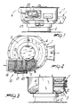
- the vibrating machine particularly for the mass drying of metallic bodies, with automatic unloading of the dried parts, according to the invention, comprises a tank body generally indicated by the reference numeral 1 which is provided with vibrating means and is associated with a base supporting frame 2 with the interposition of conventional anti-vibration means which are not described herein in detail.
- the tank body 1 internally defines a bottom 3 with a substantially circular extension which has a ramp-like portion 4 leading into a selection plane generally indicated by the reference numeral 10.
- Said selection plane 10 is provided with an initial portion 11, advantageously of the grid-shaped kind, which is arranged above electric heating resistors 12 which have the function of heating and drying the grit or loose material which is intermixed between the various parts being processed.
- the peculiarity of the invention is constituted by the fact that the central openable portion 13 is constituted by a first wing 20 with a grid-shaped configuration, which is pivoted at the edge contiguous to the initial portion 11, is and by a second wing 21 which is in turn pivoted at the edge contiguous to the terminal portion 14.
- the first wing has a width, in the direction of passage of the material, which is smaller than the second wing 21.
- the wings 20 and 21 are rotatable about their pivoting axis to assume different positions for the passage from the working position to the unloading position and vice versa.
- the rotation of the wings 20 and 21 is advantageously performed by means of a first and second cylinder, respectively indicated at 22 and 23, which act on the pivoting pin and perform the rotation.
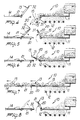
- the first wing 20 in the working position, i.e., in the position in which the various parts are continuously re-inserted into the tank, the first wing 20 is in a lowered position, i.e., directed towards the bottom of the tank, whereas the second wing 21 is in raised position, i.e., directed upwardly.
- the material carried by the vibration onto the selection plane creates a first selection with separation of the grit and loose material which falls onto the electric resistors 12, whereas the various parts being machined, indicated by the reference numeral 15, are re-inserted toward the bottom of the tank.
- the first wing is first rotated upward (figure 5), thus creating a temporary barrier for the passage of the parts being processed, which are thus retained.
- the second wing 21 is simultaneously rotated downward until it engages a stop abutment 30; the second wing 22 moves to align with the terminal portion 14.
- the first wing 20 is rotated downward and becomes arranged in alignment with the second wing, thus defining a continuous selection plane (figure 7) which allows the outward unloading of the parts.
- first wing and the second wing are provided, at the edges of mutual contact, with opposite shaped portions, indicated by the reference numerals 31 and 32, which allow to provide a rabbet-like coupling, with the first wing in practice resting on the edge of the second wing.
- the first wing is rotated upward, thus releasing the second wing, which is rotatable upward, whereas the first wing is rotated downward, thus returning to the working conditions illustrated in figure 4.
- the invention achieves the proposed aim and objects; in particular, the fact is stressed that the substantial splitting in two of the openable central portion of the selection plane allows to completely automate the operation of the vibrating machine which can be time-controlled, so as to perform the process for a certain presettable time period and then automatically perform the step of unloading the dried parts without running the risk of trapping the parts during the movement of the openable central portion.
- the presence of the related abutment wings provided on the coupling edges of the wings 20 and 21 allows to provide a precise rest position for the first wing on the second wing which ensures the continuity of the selection plane so as to achieve easy unloading of the product toward the outside of the machine.
- the materials employed may be any according to the requirements.
Landscapes
- Engineering & Computer Science (AREA)
- Mechanical Engineering (AREA)
- General Engineering & Computer Science (AREA)
- Drying Of Solid Materials (AREA)
Priority Applications (1)
| Application Number | Priority Date | Filing Date | Title |
|---|---|---|---|
| AT90110047T ATE88262T1 (de) | 1989-06-02 | 1990-05-28 | Vibrationsgeraet, insbesondere fuer die massenweise trocknung von metallischen koerpern, mit automatischem ausgeben der getrockneten teile. |
Applications Claiming Priority (2)
| Application Number | Priority Date | Filing Date | Title |
|---|---|---|---|
| IT8920775A IT1229440B (it) | 1989-06-02 | 1989-06-02 | Macchina a vibrazione particolarmente per l'asciugatura in massa di corpi metallici con scarico automatico dei pezzi asciugati. |
| IT2077589 | 1989-06-02 |
Publications (2)
| Publication Number | Publication Date |
|---|---|
| EP0400516A1 true EP0400516A1 (fr) | 1990-12-05 |
| EP0400516B1 EP0400516B1 (fr) | 1993-04-14 |
Family
ID=11171886
Family Applications (1)
| Application Number | Title | Priority Date | Filing Date |
|---|---|---|---|
| EP90110047A Expired - Lifetime EP0400516B1 (fr) | 1989-06-02 | 1990-05-28 | Machine vibrante, en particulier pour le séchage en masse de pièces métalliques, à déchargement automatique des pièces séchées |
Country Status (5)
| Country | Link |
|---|---|
| EP (1) | EP0400516B1 (fr) |
| AT (1) | ATE88262T1 (fr) |
| DE (1) | DE69001322T2 (fr) |
| ES (1) | ES2039994T3 (fr) |
| IT (1) | IT1229440B (fr) |
Cited By (6)
| Publication number | Priority date | Publication date | Assignee | Title |
|---|---|---|---|---|
| EP0882424A1 (fr) * | 1997-05-30 | 1998-12-09 | Hyppocampus S.r.l. | Machine pour sécher, polir et lustrer des couverts ou des ustensils de cuisine en métal |
| EP1523931A1 (fr) * | 2003-10-17 | 2005-04-20 | Nicem S.P.A. | Machine avec récipient vibrant pour le séchage et le polissage de couvert |
| EP1304068A3 (fr) * | 2001-10-18 | 2006-03-08 | Hyppocampus S.r.l. | Machine pour sécher, polir et lustrer des couverts ou des ustensils de cuisine en métal |
| ES2317783A1 (es) * | 2000-10-19 | 2009-04-16 | Comercial Frucosol, S.L. | Mejoras en la patente numero 200002508 referenta a maquina secadora y abrillantadora de cubiertos y articulos metalicos de mesa. |
| ES2368045A1 (es) * | 2008-07-08 | 2011-11-14 | Comercial Frucosol, S.L | MEJORAS INTRODUCIDAS EN LA PATENTE DE INVENCIÓN Nº 200002508, POR MÁQUINA SECADORA Y ABRILLANTADORA DE CUBIERTOS Y ARTÍCULOS METALICOS DE MESA. |
| WO2021008883A1 (fr) * | 2019-07-12 | 2021-01-21 | Rösler Holding Gmbh | Sécheur circulaire vibrant |
Citations (7)
| Publication number | Priority date | Publication date | Assignee | Title |
|---|---|---|---|---|
| GB928121A (en) * | 1960-12-23 | 1963-06-06 | Rice Growers Ass Of California | Method and apparatus for uniformly heating particulate material |
| US3868213A (en) * | 1973-10-25 | 1975-02-25 | Valery Petrovich Shulika | Vibration furnace |
| DE8313539U1 (de) * | 1983-05-06 | 1986-09-18 | Max Spaleck Gmbh & Co Kg, 4290 Bocholt | Vibrationsgleitschleifmaschine |
| EP0229297A2 (fr) * | 1986-01-13 | 1987-07-22 | Carl Kurt Walther GmbH & Co. KG | Polisseuse vibrante à bac annulaire |
| DE3703545A1 (de) * | 1987-02-06 | 1988-08-18 | Walther Carl Kurt Gmbh | Wahlweise wirksame austrags- und trenneinrichtung an vibrations-scheuerbehaeltern |
| EP0282937A2 (fr) * | 1987-03-17 | 1988-09-21 | RENI-CIRILLO S.r.l. | Machine vibrante pour le séchage de pièces métalliques au moyen d'air chaud et de matière absorbante |
| DE8717565U1 (de) * | 1987-11-17 | 1989-03-16 | Roland Rösler Oberflächentechnik KG, 8623 Staffelstein | Durchlaufanlage |
-
1989
- 1989-06-02 IT IT8920775A patent/IT1229440B/it active
-
1990
- 1990-05-28 ES ES199090110047T patent/ES2039994T3/es not_active Expired - Lifetime
- 1990-05-28 AT AT90110047T patent/ATE88262T1/de not_active IP Right Cessation
- 1990-05-28 DE DE9090110047T patent/DE69001322T2/de not_active Expired - Fee Related
- 1990-05-28 EP EP90110047A patent/EP0400516B1/fr not_active Expired - Lifetime
Patent Citations (7)
| Publication number | Priority date | Publication date | Assignee | Title |
|---|---|---|---|---|
| GB928121A (en) * | 1960-12-23 | 1963-06-06 | Rice Growers Ass Of California | Method and apparatus for uniformly heating particulate material |
| US3868213A (en) * | 1973-10-25 | 1975-02-25 | Valery Petrovich Shulika | Vibration furnace |
| DE8313539U1 (de) * | 1983-05-06 | 1986-09-18 | Max Spaleck Gmbh & Co Kg, 4290 Bocholt | Vibrationsgleitschleifmaschine |
| EP0229297A2 (fr) * | 1986-01-13 | 1987-07-22 | Carl Kurt Walther GmbH & Co. KG | Polisseuse vibrante à bac annulaire |
| DE3703545A1 (de) * | 1987-02-06 | 1988-08-18 | Walther Carl Kurt Gmbh | Wahlweise wirksame austrags- und trenneinrichtung an vibrations-scheuerbehaeltern |
| EP0282937A2 (fr) * | 1987-03-17 | 1988-09-21 | RENI-CIRILLO S.r.l. | Machine vibrante pour le séchage de pièces métalliques au moyen d'air chaud et de matière absorbante |
| DE8717565U1 (de) * | 1987-11-17 | 1989-03-16 | Roland Rösler Oberflächentechnik KG, 8623 Staffelstein | Durchlaufanlage |
Cited By (8)
| Publication number | Priority date | Publication date | Assignee | Title |
|---|---|---|---|---|
| EP0882424A1 (fr) * | 1997-05-30 | 1998-12-09 | Hyppocampus S.r.l. | Machine pour sécher, polir et lustrer des couverts ou des ustensils de cuisine en métal |
| ES2317783A1 (es) * | 2000-10-19 | 2009-04-16 | Comercial Frucosol, S.L. | Mejoras en la patente numero 200002508 referenta a maquina secadora y abrillantadora de cubiertos y articulos metalicos de mesa. |
| ES2317783B1 (es) * | 2000-10-19 | 2010-02-11 | Comercial Frucosol, S.L. | Mejoras en la patente numero 200002508 referenta a maquina secadora y abrillantadora de cubiertos y articulos metalicos de mesa. |
| EP1304068A3 (fr) * | 2001-10-18 | 2006-03-08 | Hyppocampus S.r.l. | Machine pour sécher, polir et lustrer des couverts ou des ustensils de cuisine en métal |
| EP1523931A1 (fr) * | 2003-10-17 | 2005-04-20 | Nicem S.P.A. | Machine avec récipient vibrant pour le séchage et le polissage de couvert |
| ES2368045A1 (es) * | 2008-07-08 | 2011-11-14 | Comercial Frucosol, S.L | MEJORAS INTRODUCIDAS EN LA PATENTE DE INVENCIÓN Nº 200002508, POR MÁQUINA SECADORA Y ABRILLANTADORA DE CUBIERTOS Y ARTÍCULOS METALICOS DE MESA. |
| WO2021008883A1 (fr) * | 2019-07-12 | 2021-01-21 | Rösler Holding Gmbh | Sécheur circulaire vibrant |
| US12331994B2 (en) | 2019-07-12 | 2025-06-17 | Rösler Holding Gmbh | Vibrating round device |
Also Published As
| Publication number | Publication date |
|---|---|
| ES2039994T3 (es) | 1993-10-01 |
| IT1229440B (it) | 1991-08-08 |
| ATE88262T1 (de) | 1993-04-15 |
| DE69001322T2 (de) | 1993-07-22 |
| DE69001322D1 (de) | 1993-05-19 |
| EP0400516B1 (fr) | 1993-04-14 |
| IT8920775A0 (it) | 1989-06-02 |
Similar Documents
| Publication | Publication Date | Title |
|---|---|---|
| EP0400516A1 (fr) | Machine vibrante, en particulier pour le séchage en masse de pièces métalliques, à déchargement automatique des pièces séchées | |
| US5072495A (en) | Installation for automatic assembly of socket-bracket | |
| US4391769A (en) | Apparatus for loading unvulcanized tires on tire vulcanizing machine | |
| JPS63169209A (ja) | 自動バリ取り装置 | |
| WO1989000964A3 (fr) | Procede et dispositif de transfert automatique de vetements a des plieuses automatiques et cintres de transport | |
| US3945921A (en) | Rotary centrifugal machine | |
| US4622909A (en) | Method and apparatus for applying a gusset to manufactured articles | |
| US2879545A (en) | Apparatus for separating and clamping mold sections in rotational casting machines | |
| JP3295383B2 (ja) | 自動脱水処理装置 | |
| US4575949A (en) | Press for pressing batches of articles dry | |
| IT201800009955A1 (it) | Metodo e apparato per il prelievo e la movimentazione di scampoli di pellame o simile materiale | |
| EP0468344A1 (fr) | Dispositif de chargement et de déchargement pour pneus de véhicules | |
| US5438775A (en) | Method and machine for automatically ironing and stacking men's socks | |
| US5442841A (en) | Hoisery trimming apparatus | |
| US2166461A (en) | Work supporting table | |
| CN115026575A (zh) | 一种刀头刀网全自动嵌合设备 | |
| EP0400515B1 (fr) | Machine vibrante, en particulier pour la finition de surfaces de pièces, avec dispositif de déchargement automatique | |
| JPH0232963B2 (fr) | ||
| US4211752A (en) | Hinged load dumping door for multi-cell extractors | |
| EP0396511A2 (fr) | Appareil pour remplacer des pièces de tissu dans des matelasseuses | |
| KR19990080300A (ko) | 필터 베이스플레이트의 탭핑장치 | |
| KR830000662B1 (ko) | 프레시 브루식 코오피 자동판매기에 있어서의 코오피 추출기구 | |
| KR200141812Y1 (ko) | 타이어 가류용 블래더 식출제거장치 | |
| GB1597419A (en) | Manufacture of ceramic ware | |
| KR950007646Y1 (ko) | 의류용 패치(patch)의 재봉기에 있어 패치의 자동이송 및 적재장치 |
Legal Events
| Date | Code | Title | Description |
|---|---|---|---|
| PUAI | Public reference made under article 153(3) epc to a published international application that has entered the european phase |
Free format text: ORIGINAL CODE: 0009012 |
|
| AK | Designated contracting states |
Kind code of ref document: A1 Designated state(s): AT CH DE ES FR GB IT LI NL SE |
|
| 17P | Request for examination filed |
Effective date: 19910507 |
|
| 17Q | First examination report despatched |
Effective date: 19920114 |
|
| GRAA | (expected) grant |
Free format text: ORIGINAL CODE: 0009210 |
|
| AK | Designated contracting states |
Kind code of ref document: B1 Designated state(s): AT CH DE ES FR GB IT LI NL SE |
|
| PG25 | Lapsed in a contracting state [announced via postgrant information from national office to epo] |
Ref country code: SE Effective date: 19930414 Ref country code: NL Effective date: 19930414 Ref country code: AT Effective date: 19930414 |
|
| REF | Corresponds to: |
Ref document number: 88262 Country of ref document: AT Date of ref document: 19930415 Kind code of ref document: T |
|
| REF | Corresponds to: |
Ref document number: 69001322 Country of ref document: DE Date of ref document: 19930519 |
|
| ET | Fr: translation filed | ||
| ITF | It: translation for a ep patent filed | ||
| NLV1 | Nl: lapsed or annulled due to failure to fulfill the requirements of art. 29p and 29m of the patents act | ||
| REG | Reference to a national code |
Ref country code: ES Ref legal event code: FG2A Ref document number: 2039994 Country of ref document: ES Kind code of ref document: T3 |
|
| PLBE | No opposition filed within time limit |
Free format text: ORIGINAL CODE: 0009261 |
|
| STAA | Information on the status of an ep patent application or granted ep patent |
Free format text: STATUS: NO OPPOSITION FILED WITHIN TIME LIMIT |
|
| 26N | No opposition filed | ||
| REG | Reference to a national code |
Ref country code: GB Ref legal event code: IF02 |
|
| PGFP | Annual fee paid to national office [announced via postgrant information from national office to epo] |
Ref country code: GB Payment date: 20020422 Year of fee payment: 13 Ref country code: ES Payment date: 20020422 Year of fee payment: 13 |
|
| PGFP | Annual fee paid to national office [announced via postgrant information from national office to epo] |
Ref country code: DE Payment date: 20020425 Year of fee payment: 13 |
|
| PGFP | Annual fee paid to national office [announced via postgrant information from national office to epo] |
Ref country code: FR Payment date: 20020430 Year of fee payment: 13 |
|
| PGFP | Annual fee paid to national office [announced via postgrant information from national office to epo] |
Ref country code: CH Payment date: 20020711 Year of fee payment: 13 |
|
| PG25 | Lapsed in a contracting state [announced via postgrant information from national office to epo] |
Ref country code: GB Free format text: LAPSE BECAUSE OF NON-PAYMENT OF DUE FEES Effective date: 20030528 |
|
| PG25 | Lapsed in a contracting state [announced via postgrant information from national office to epo] |
Ref country code: ES Free format text: LAPSE BECAUSE OF NON-PAYMENT OF DUE FEES Effective date: 20030529 |
|
| PG25 | Lapsed in a contracting state [announced via postgrant information from national office to epo] |
Ref country code: LI Free format text: LAPSE BECAUSE OF NON-PAYMENT OF DUE FEES Effective date: 20030531 Ref country code: CH Free format text: LAPSE BECAUSE OF NON-PAYMENT OF DUE FEES Effective date: 20030531 |
|
| PG25 | Lapsed in a contracting state [announced via postgrant information from national office to epo] |
Ref country code: DE Free format text: LAPSE BECAUSE OF NON-PAYMENT OF DUE FEES Effective date: 20031202 |
|
| REG | Reference to a national code |
Ref country code: CH Ref legal event code: PL |
|
| GBPC | Gb: european patent ceased through non-payment of renewal fee |
Effective date: 20030528 |
|
| PG25 | Lapsed in a contracting state [announced via postgrant information from national office to epo] |
Ref country code: FR Free format text: LAPSE BECAUSE OF NON-PAYMENT OF DUE FEES Effective date: 20040130 |
|
| REG | Reference to a national code |
Ref country code: FR Ref legal event code: ST |
|
| REG | Reference to a national code |
Ref country code: ES Ref legal event code: FD2A Effective date: 20030529 |
|
| PGFP | Annual fee paid to national office [announced via postgrant information from national office to epo] |
Ref country code: IT Payment date: 20060531 Year of fee payment: 17 |
|
| PG25 | Lapsed in a contracting state [announced via postgrant information from national office to epo] |
Ref country code: IT Free format text: LAPSE BECAUSE OF NON-PAYMENT OF DUE FEES Effective date: 20070528 |