EP0468344A1 - Dispositif de chargement et de déchargement pour pneus de véhicules - Google Patents
Dispositif de chargement et de déchargement pour pneus de véhicules Download PDFInfo
- Publication number
- EP0468344A1 EP0468344A1 EP91111889A EP91111889A EP0468344A1 EP 0468344 A1 EP0468344 A1 EP 0468344A1 EP 91111889 A EP91111889 A EP 91111889A EP 91111889 A EP91111889 A EP 91111889A EP 0468344 A1 EP0468344 A1 EP 0468344A1
- Authority
- EP
- European Patent Office
- Prior art keywords
- unit
- tire
- unloading
- loading
- fact
- Prior art date
- Legal status (The legal status is an assumption and is not a legal conclusion. Google has not performed a legal analysis and makes no representation as to the accuracy of the status listed.)
- Granted
Links
- 230000003213 activating effect Effects 0.000 claims description 3
- 239000000725 suspension Substances 0.000 abstract 1
- 230000008878 coupling Effects 0.000 description 4
- 238000010168 coupling process Methods 0.000 description 4
- 238000005859 coupling reaction Methods 0.000 description 4
- 239000011324 bead Substances 0.000 description 3
- 238000000034 method Methods 0.000 description 2
- 238000004519 manufacturing process Methods 0.000 description 1
- 230000000284 resting effect Effects 0.000 description 1
Images


Classifications
-
- B—PERFORMING OPERATIONS; TRANSPORTING
- B29—WORKING OF PLASTICS; WORKING OF SUBSTANCES IN A PLASTIC STATE IN GENERAL
- B29D—PRODUCING PARTICULAR ARTICLES FROM PLASTICS OR FROM SUBSTANCES IN A PLASTIC STATE
- B29D30/00—Producing pneumatic or solid tyres or parts thereof
- B29D30/06—Pneumatic tyres or parts thereof (e.g. produced by casting, moulding, compression moulding, injection moulding, centrifugal casting)
- B29D30/0601—Vulcanising tyres; Vulcanising presses for tyres
- B29D30/0603—Loading or unloading the presses
Definitions
- the present invention relates to a vehicle tire loading-unloading device.
- the present invention relates to a loading-unloading device for a tire processing machine, and which may be employed to advantage for loading/unloading tires on/off a curing unit comprising an upper half mold, a lower half mold and a device for parting the two half molds at the end of each curing cycle; and wherein the two half molds are so formed that, when parted, the cured tire remains integral with the upper half mold.
- the principal aim of the present invention is to provide a loading-unloading device designed to minimize the downtime involved on a tire manufacturing machine, particularly a curing unit of the aforementioned type, for loading and unloading the unprocessed and processed tires respectively.
- a device for loading- unloading vehicle in particular motor vehicle, tires, characterised by the fact that it comprises a mobile loading-unloading unit in turn comprising an upper unit having plate means for supporting a first tire, and a lower unit having means whereby to suspend a second tire; fixed supporting means for said mobile loading-unloading unit; and activating means for moving said mobile loading-unloading unit through a processing unit and between a loading station, wherein said second tire is loaded, and an unloading station, wherein said first tire is unloaded.
- Number 1 in Fig.1 indicates a tire curing system comprising a conveyor 2 for successively feeding green tires 3 to a loading station 4; a curing unit 5 for receiving tires 3 and producing cured tires 6; a conveyor 7 for transferring tires 6 from an unloading station 8; and a device 9 for transferring both tires 3 from loading station 4 to curing unit 5, and tires 6 from curing unit 5 to unloading station 8.
- Curing unit 5 is of known type as described, for example, in US Patent n.4,747,765, the content of which is fully incorporated herein.
- Unit 5 comprises a lower portion 10 and an upper portion 11 designed to move in relation to each other, by virtue of hydraulic lifting devices 12, between a closed curing position (not shown) and an open position (Fig.1) for unloading tire 6 and loading tire 3.
- Device 9 comprises two guide columns 13 extending upwards from a fixed base 14 and connected by an upper crosspiece 15 designed to move parallel to a vertical axis 16 in relation to base 14 by virtue of a hydraulic actuator 17.
- Crosspiece 15 is connected to a coupling 18 coaxial with axis 16 and connected to an actuator 19 so as to turn in relation to crosspiece 15 about axis 16.
- Device 9 also comprises a mobile loading and unloading unit 23 connected integral with the free end of portion 22 of arm 20.
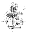
- unit 23 comprises an upper unit 24 for supporting tire 6, and a lower unit 25 for suspending tire 3 coaxially with tire 6.
- Unit 24 comprises a cylindrical body 26 integral with the free end of portion 22 of arm 20 and having a vertical axis 27.
- the top end of body 26 is fitted with a plate 28 defined externally by an upward-tapering, substantially truncated-cone surface 29 coaxial with axis 27.
- the bottom end of plate 28 presents an outer flange 30 defining a support for the bead portion 31 of tire 6.
- Unit 25 is connected integral with the bottom end of body 26, and comprises a known device 32 for gripping tire 3.
- Device 32 comprises, in known manner, a central actuator 33 integral with the bottom end of body 26 and having a number of output rods 34 moving substantially radially between a withdrawn position (not shown) and an expanded position (as shown in Fig.2).
- Each rod 34 is fitted on its free end with a pin 35 parallel to axis 27 and fitted on its bottom end with a substantially T-shaped bracket 36 designed to support and grip the bead portion of tire 3 and suspend tire 3 beneath body 26.
- actuator 19 is operated for positioning unit 23 over tire 3 in loading station 4; and actuator 17 is operated for lowering unit 23, gripping tire 3 via gripping device 32, and raising unit 23 with tire 3 suspended on unit 25.
- Actuator 19 is then operated once more for moving arm 20 towards curing unit 5 and positioning unit 23 between upper and lower portions 11 and 10 already opened by hydraulic devices 12.
- unit 23 is coaxial with portions 10 and 11 of curing unit 5, gripping device 32 is operated so as to withdraw rods 34 and drop tire 3 inside lower half mold 37 on lower portion 10 of unit 5. Unit 23 is then withdrawn from unit 5, which is closed for curing tire 3 and producing cured tire 6.
- unit 23 is moved into station 4 for picking up another tire 3 and transferring it to unit 5.
- portions 10 and 11 are parted by devices 12, which results, in known manner, in tire 6 being detached from lower portion 10 and remaining attached to upper portion 11.
- Unit 23 is then inserted once more between portions 10 and 11, so that unit 24 is located beneath tire 6 attached to portion 11, and unit 25, to which the next tire 3 is suspended, is located over lower half mold 37.
- tire 6 is detached from portion 11 by a known extracting device 38 and dropped on to plate 28 with its bead portion 31 substantially resting on flange 30, and the next tire 3 is dropped on to half mold 37 by withdrawing rods 34 on device 32.
- unit 23 is then withdrawn from curing unit 5; moved over to unloading station 8; turned over, by rotating portion 22 of arm 20, so as to unload tire 6 on to conveyor 7; restored to the normal position with unit 24 upwards; and, finally, returned to loading station 4 to pick up the next tire 3 via device 32 and await the next unit 5 unloading-loading cycle.
- a vertical guide 40 having the same function as columns 13 in Fig.1 is connected to an apron 39 fitted to lower portion 10 of unit 5 for connecting lifting devices 12.
- Guide 40 is defined, at its opposite ends, by two transverse plates 41 between which is mounted for rotation a screw 42 which, together with its drive motor 43, constitutes an actuator, similar to 17 in Fig.1, for moving along guide 40 a slide 44 similar to crosspiece 15 and connected in sliding manner to guide 40.
- Slide 44 is connected integral with a fork 45 supporting a rotary pin 46 extending along an axis 47 corresponding with axis 26 in Fig.1, and powered (in a manner not shown) so as to turn about axis 47.
- Pin 46 is connected integral with the outer casing of an angular actuator 48 constituting a first portion of arm 20, the second portion 22 of which is connected to loading-unloading unit 23, extends along axis 21, and is designed to turn about axis 21 by virtue of actuator 48.
Landscapes
- Engineering & Computer Science (AREA)
- Mechanical Engineering (AREA)
- Moulds For Moulding Plastics Or The Like (AREA)
- Heating, Cooling, Or Curing Plastics Or The Like In General (AREA)
- Control Of Transmission Device (AREA)
Applications Claiming Priority (2)
| Application Number | Priority Date | Filing Date | Title |
|---|---|---|---|
| IT6759290 | 1990-07-27 | ||
| IT67592A IT1240507B (it) | 1990-07-27 | 1990-07-27 | Dispositivo caricatore-scaricatore di pneumatici di veicoli |
Publications (2)
| Publication Number | Publication Date |
|---|---|
| EP0468344A1 true EP0468344A1 (fr) | 1992-01-29 |
| EP0468344B1 EP0468344B1 (fr) | 1995-09-13 |
Family
ID=11303700
Family Applications (1)
| Application Number | Title | Priority Date | Filing Date |
|---|---|---|---|
| EP91111889A Expired - Lifetime EP0468344B1 (fr) | 1990-07-27 | 1991-07-16 | Dispositif de chargement et de déchargement pour pneus de véhicules |
Country Status (6)
| Country | Link |
|---|---|
| US (1) | US5206031A (fr) |
| EP (1) | EP0468344B1 (fr) |
| JP (1) | JP3190375B2 (fr) |
| DE (1) | DE69112947T2 (fr) |
| ES (1) | ES2077735T3 (fr) |
| IT (1) | IT1240507B (fr) |
Cited By (3)
| Publication number | Priority date | Publication date | Assignee | Title |
|---|---|---|---|---|
| WO2004016414A3 (fr) * | 2002-08-16 | 2004-08-26 | John R Cole | Dispositif et procede de verrouillage d'une presse de vulcanisation de pneumatiques |
| WO2014097016A1 (fr) * | 2012-12-20 | 2014-06-26 | Pirelli Tyre S.P.A. | Procédé pour contrôler la géométrie de pneus verts différents les uns des autres et procédé pour la fabrication de pneus différents les uns des autres |
| WO2017129156A1 (fr) * | 2016-01-26 | 2017-08-03 | Harburg-Freudenberger Maschinenbau Gmbh | Procédé et dispositif permettant de soumettre des pneumatiques à un traitement ultérieur |
Families Citing this family (4)
| Publication number | Priority date | Publication date | Assignee | Title |
|---|---|---|---|---|
| US6582212B1 (en) * | 1998-11-25 | 2003-06-24 | Kabushiki Kaisha Kobe Seiko Sho | Tire vulcanizer and tire vulcanizing equipment equipped with the tire vulcanizer |
| JP4773620B2 (ja) * | 2001-01-09 | 2011-09-14 | 三菱重工業株式会社 | タイヤ加硫機、タイヤ加硫装置およびタイヤ加硫方法 |
| US6890165B2 (en) * | 2001-01-09 | 2005-05-10 | Ichimaru Giken Co., Ltd. | Tire catching device of post-vulcanization inflating device |
| WO2016078637A1 (fr) | 2014-11-18 | 2016-05-26 | Harburg-Freudenberger Maschinenbau Gmbh | Dispositif et unité de transport pour la manipulation de pneus crus |
Citations (4)
| Publication number | Priority date | Publication date | Assignee | Title |
|---|---|---|---|---|
| DE2237153A1 (de) * | 1972-07-28 | 1974-02-07 | Collmann Gmbh & Co Spezialmasc | Vorrichtung zum transport eines kfzreifens in eine und aus einer pruef- oder bearbeitungslage |
| FR2370574A1 (fr) * | 1976-11-15 | 1978-06-09 | Pirelli | Dispositif pour le centrage reciproque d'elements mecaniques mobiles l'un par rapport a l'autre, particulierement destine a etre utilise sur les presses de vulcanisation pour pneumatiques |
| US4391769A (en) * | 1980-06-14 | 1983-07-05 | Bridgestone Tire Co., Ltd. | Apparatus for loading unvulcanized tires on tire vulcanizing machine |
| EP0154612A2 (fr) * | 1984-02-29 | 1985-09-11 | CIMA IMPIANTI S.p.A. | Dispositif pour charger et décharger des pneus dans une installation de vulcanisation |
Family Cites Families (14)
| Publication number | Priority date | Publication date | Assignee | Title |
|---|---|---|---|---|
| US1895909A (en) * | 1932-04-07 | 1933-01-31 | Goodrich Co B F | Method of and apparatus for loosening and removing articles from molds |
| US2066265A (en) * | 1933-11-25 | 1936-12-29 | Wingfoot Corp | Method of curing tires |
| US3008180A (en) * | 1958-05-29 | 1961-11-14 | Goodyear Tire & Rubber | Apparatus for automatically post-cure inflating nylon tires |
| US3170187A (en) * | 1960-05-23 | 1965-02-23 | Nrm Corp | Tire curing press with dual post inflators |
| NL123663C (fr) * | 1960-08-19 | |||
| US3645660A (en) * | 1966-11-22 | 1972-02-29 | Uniroyal Inc | Apparatus for jet air cooling of tires during postinflation |
| US3483596A (en) * | 1967-06-12 | 1969-12-16 | Amk Subsidiary Corp | Tire post cure inflator |
| US3667881A (en) * | 1971-03-03 | 1972-06-06 | Goodrich Co B F | Tire cooling |
| US3692444A (en) * | 1971-05-05 | 1972-09-19 | Uniroyal Inc | Apparatus for cooling tires during post inflation |
| US3712769A (en) * | 1971-06-03 | 1973-01-23 | Goodrich Co B F | Fire loading apparatus with preheating device for green tires |
| BE798126A (fr) * | 1973-04-14 | 1973-07-31 | Gazuit Georges | Chargeur pour presse a vulcaniser les pneumatiques |
| US4092090A (en) * | 1977-05-18 | 1978-05-30 | Nrm Corporation | Tire curing system |
| US4447385A (en) * | 1983-08-01 | 1984-05-08 | Nrm Corporation | Tire press, loader and method |
| US4702669A (en) * | 1985-10-24 | 1987-10-27 | Kabushiki Kaisha Kobe Seiko Sho | Mechanism for transferring cured tires from tire press to post-inflator |
-
1990
- 1990-07-27 IT IT67592A patent/IT1240507B/it active IP Right Grant
-
1991
- 1991-07-03 US US07/725,158 patent/US5206031A/en not_active Expired - Lifetime
- 1991-07-16 ES ES91111889T patent/ES2077735T3/es not_active Expired - Lifetime
- 1991-07-16 DE DE69112947T patent/DE69112947T2/de not_active Expired - Fee Related
- 1991-07-16 EP EP91111889A patent/EP0468344B1/fr not_active Expired - Lifetime
- 1991-07-26 JP JP20870591A patent/JP3190375B2/ja not_active Expired - Fee Related
Patent Citations (4)
| Publication number | Priority date | Publication date | Assignee | Title |
|---|---|---|---|---|
| DE2237153A1 (de) * | 1972-07-28 | 1974-02-07 | Collmann Gmbh & Co Spezialmasc | Vorrichtung zum transport eines kfzreifens in eine und aus einer pruef- oder bearbeitungslage |
| FR2370574A1 (fr) * | 1976-11-15 | 1978-06-09 | Pirelli | Dispositif pour le centrage reciproque d'elements mecaniques mobiles l'un par rapport a l'autre, particulierement destine a etre utilise sur les presses de vulcanisation pour pneumatiques |
| US4391769A (en) * | 1980-06-14 | 1983-07-05 | Bridgestone Tire Co., Ltd. | Apparatus for loading unvulcanized tires on tire vulcanizing machine |
| EP0154612A2 (fr) * | 1984-02-29 | 1985-09-11 | CIMA IMPIANTI S.p.A. | Dispositif pour charger et décharger des pneus dans une installation de vulcanisation |
Cited By (11)
| Publication number | Priority date | Publication date | Assignee | Title |
|---|---|---|---|---|
| WO2004016414A3 (fr) * | 2002-08-16 | 2004-08-26 | John R Cole | Dispositif et procede de verrouillage d'une presse de vulcanisation de pneumatiques |
| US6908584B2 (en) | 2002-08-16 | 2005-06-21 | John R. Cole | Apparatus and method for locking a tire vulcanizing press |
| US6981857B2 (en) | 2002-08-16 | 2006-01-03 | Cole John R | Apparatus and method for locking a tire vulcanizing press |
| US7320580B2 (en) | 2002-08-16 | 2008-01-22 | Cole John R | Apparatus and method for loading and unloading a tire press |
| US7442335B2 (en) | 2002-08-16 | 2008-10-28 | Cole John R | Apparatus and method for loading and unloading a tire press |
| HRP20050150B1 (hr) * | 2002-08-16 | 2013-03-31 | John R. Cole | Sprave i metode za zabravljivanje preše za vulkaniziranje gume |
| WO2014097016A1 (fr) * | 2012-12-20 | 2014-06-26 | Pirelli Tyre S.P.A. | Procédé pour contrôler la géométrie de pneus verts différents les uns des autres et procédé pour la fabrication de pneus différents les uns des autres |
| CN104853906A (zh) * | 2012-12-20 | 2015-08-19 | 倍耐力轮胎股份公司 | 用于控制彼此不同的生轮胎的几何形状的方法和用于制造彼此不同的轮胎的处理 |
| CN104853906B (zh) * | 2012-12-20 | 2017-10-17 | 倍耐力轮胎股份公司 | 用于控制彼此不同的生轮胎的几何形状的方法和用于制造彼此不同的轮胎的处理 |
| WO2017129156A1 (fr) * | 2016-01-26 | 2017-08-03 | Harburg-Freudenberger Maschinenbau Gmbh | Procédé et dispositif permettant de soumettre des pneumatiques à un traitement ultérieur |
| US11511505B2 (en) | 2016-01-26 | 2022-11-29 | Harburg-Freudenberger Maschinenbau Gmbh | Method and device for post-treating tyres |
Also Published As
| Publication number | Publication date |
|---|---|
| ES2077735T3 (es) | 1995-12-01 |
| DE69112947D1 (de) | 1995-10-19 |
| EP0468344B1 (fr) | 1995-09-13 |
| IT9067592A1 (it) | 1992-01-27 |
| JP3190375B2 (ja) | 2001-07-23 |
| US5206031A (en) | 1993-04-27 |
| JPH04226305A (ja) | 1992-08-17 |
| DE69112947T2 (de) | 1996-04-11 |
| IT1240507B (it) | 1993-12-17 |
| IT9067592A0 (it) | 1990-07-27 |
Similar Documents
| Publication | Publication Date | Title |
|---|---|---|
| CN101405131A (zh) | 轮胎成形用刚性型芯的分离取出方法及其装置 | |
| EP0468344B1 (fr) | Dispositif de chargement et de déchargement pour pneus de véhicules | |
| US4304619A (en) | Method and apparatus for off-loading a completed uncured tire | |
| EP0289469B1 (fr) | Presse de vulcanisation de pneus avec dispositif de chargement et de déchargement des pneus | |
| EP2072227B1 (fr) | Appareil de déchargement de pneu et procédé dans une ligne de vulcanisation | |
| CA1236050A (fr) | Systeme code de tri et de manutention de pneumatiques selon leurs types de semelles | |
| US4526267A (en) | Method and apparatus for storing and transferring tires to a hook conveyor | |
| US5198234A (en) | Vehicle tire loading-unloading and stabilizing device | |
| EP2072238A1 (fr) | Appareil et procédé d'assemblage, désassemblage et stockage d'un élément de fabrication de pneu | |
| EP2072229A1 (fr) | Ensemble principal de fabrication de pneu et station de désassemblage et procédé | |
| EP2072228B1 (fr) | Appareil et procédé de manipulation de noyau de fabrication de pneu | |
| JP2579125B2 (ja) | ケーキ取出し・装着装置 | |
| US7896632B2 (en) | Apparatus for disassembling a tire building core | |
| JPH0740462A (ja) | タイヤ用ビードの成形装置 | |
| JP2698032B2 (ja) | 台タイヤの自動投入・取り出し方法及びその装置 | |
| EP2072239B1 (fr) | Appareil et procédé de manipulateur de segment central de fabrication de pneu | |
| JPH05131452A (ja) | タイヤ加硫機のタイヤ取出装置 | |
| EP1749647A1 (fr) | Dispositif de tension d'un talon de pneu et procédé pour tenir un pneu cru | |
| JP4487118B2 (ja) | タイヤ用ビードリングラッキング方法及び装置 | |
| CN110693171B (zh) | 一种应用于化妆品的脱模机 | |
| SU758669A1 (ru) | Устройство дл отбора покрышек от сборочного станка | |
| JPH0767758B2 (ja) | 生タイヤ取出し装置 | |
| JPS6021523B2 (ja) | タイヤ加硫機におけるタイヤ取出装置 |
Legal Events
| Date | Code | Title | Description |
|---|---|---|---|
| PUAI | Public reference made under article 153(3) epc to a published international application that has entered the european phase |
Free format text: ORIGINAL CODE: 0009012 |
|
| AK | Designated contracting states |
Kind code of ref document: A1 Designated state(s): DE ES FR GB IT |
|
| 17P | Request for examination filed |
Effective date: 19920724 |
|
| 17Q | First examination report despatched |
Effective date: 19931206 |
|
| GRAA | (expected) grant |
Free format text: ORIGINAL CODE: 0009210 |
|
| AK | Designated contracting states |
Kind code of ref document: B1 Designated state(s): DE ES FR GB IT |
|
| REF | Corresponds to: |
Ref document number: 69112947 Country of ref document: DE Date of ref document: 19951019 |
|
| ITF | It: translation for a ep patent filed | ||
| ET | Fr: translation filed | ||
| REG | Reference to a national code |
Ref country code: ES Ref legal event code: FG2A Ref document number: 2077735 Country of ref document: ES Kind code of ref document: T3 |
|
| PLBE | No opposition filed within time limit |
Free format text: ORIGINAL CODE: 0009261 |
|
| STAA | Information on the status of an ep patent application or granted ep patent |
Free format text: STATUS: NO OPPOSITION FILED WITHIN TIME LIMIT |
|
| 26N | No opposition filed | ||
| RAP2 | Party data changed (patent owner data changed or rights of a patent transferred) |
Owner name: BRIDGESTONE CORPORATION |
|
| PGFP | Annual fee paid to national office [announced via postgrant information from national office to epo] |
Ref country code: GB Payment date: 19970620 Year of fee payment: 7 |
|
| PG25 | Lapsed in a contracting state [announced via postgrant information from national office to epo] |
Ref country code: GB Free format text: LAPSE BECAUSE OF NON-PAYMENT OF DUE FEES Effective date: 19980716 |
|
| GBPC | Gb: european patent ceased through non-payment of renewal fee |
Effective date: 19980716 |
|
| PGFP | Annual fee paid to national office [announced via postgrant information from national office to epo] |
Ref country code: FR Payment date: 20000707 Year of fee payment: 10 |
|
| PGFP | Annual fee paid to national office [announced via postgrant information from national office to epo] |
Ref country code: ES Payment date: 20000712 Year of fee payment: 10 |
|
| PGFP | Annual fee paid to national office [announced via postgrant information from national office to epo] |
Ref country code: DE Payment date: 20000727 Year of fee payment: 10 |
|
| PG25 | Lapsed in a contracting state [announced via postgrant information from national office to epo] |
Ref country code: ES Free format text: LAPSE BECAUSE OF NON-PAYMENT OF DUE FEES Effective date: 20010717 |
|
| PG25 | Lapsed in a contracting state [announced via postgrant information from national office to epo] |
Ref country code: FR Free format text: LAPSE BECAUSE OF NON-PAYMENT OF DUE FEES Effective date: 20020329 |
|
| PG25 | Lapsed in a contracting state [announced via postgrant information from national office to epo] |
Ref country code: DE Free format text: LAPSE BECAUSE OF NON-PAYMENT OF DUE FEES Effective date: 20020501 |
|
| REG | Reference to a national code |
Ref country code: FR Ref legal event code: ST |
|
| REG | Reference to a national code |
Ref country code: ES Ref legal event code: FD2A Effective date: 20020810 |
|
| PG25 | Lapsed in a contracting state [announced via postgrant information from national office to epo] |
Ref country code: IT Free format text: LAPSE BECAUSE OF NON-PAYMENT OF DUE FEES;WARNING: LAPSES OF ITALIAN PATENTS WITH EFFECTIVE DATE BEFORE 2007 MAY HAVE OCCURRED AT ANY TIME BEFORE 2007. THE CORRECT EFFECTIVE DATE MAY BE DIFFERENT FROM THE ONE RECORDED. Effective date: 20050716 |