EP0400627B1 - Appareil pour déterminer la concentration de NOx - Google Patents
Appareil pour déterminer la concentration de NOx Download PDFInfo
- Publication number
- EP0400627B1 EP0400627B1 EP90110296A EP90110296A EP0400627B1 EP 0400627 B1 EP0400627 B1 EP 0400627B1 EP 90110296 A EP90110296 A EP 90110296A EP 90110296 A EP90110296 A EP 90110296A EP 0400627 B1 EP0400627 B1 EP 0400627B1
- Authority
- EP
- European Patent Office
- Prior art keywords
- sensor
- passage
- sensors
- exhaust gases
- producing
- Prior art date
- Legal status (The legal status is an assumption and is not a legal conclusion. Google has not performed a legal analysis and makes no representation as to the accuracy of the status listed.)
- Expired - Lifetime
Links
- 239000007789 gas Substances 0.000 claims description 45
- 239000001301 oxygen Substances 0.000 claims description 28
- 229910052760 oxygen Inorganic materials 0.000 claims description 28
- IJGRMHOSHXDMSA-UHFFFAOYSA-N Atomic nitrogen Chemical compound N#N IJGRMHOSHXDMSA-UHFFFAOYSA-N 0.000 claims description 26
- 239000000446 fuel Substances 0.000 claims description 21
- QVGXLLKOCUKJST-UHFFFAOYSA-N atomic oxygen Chemical compound [O] QVGXLLKOCUKJST-UHFFFAOYSA-N 0.000 claims description 20
- 229910052757 nitrogen Inorganic materials 0.000 claims description 13
- 239000003792 electrolyte Substances 0.000 claims description 8
- 238000002485 combustion reaction Methods 0.000 claims description 6
- 238000011144 upstream manufacturing Methods 0.000 claims description 5
- 239000000203 mixture Substances 0.000 claims description 3
- MWUXSHHQAYIFBG-UHFFFAOYSA-N nitrogen oxide Inorganic materials O=[N] MWUXSHHQAYIFBG-UHFFFAOYSA-N 0.000 description 23
- 238000009792 diffusion process Methods 0.000 description 9
- -1 oxygen ion Chemical class 0.000 description 6
- 239000004215 Carbon black (E152) Substances 0.000 description 4
- UGFAIRIUMAVXCW-UHFFFAOYSA-N Carbon monoxide Chemical compound [O+]#[C-] UGFAIRIUMAVXCW-UHFFFAOYSA-N 0.000 description 4
- 229910002091 carbon monoxide Inorganic materials 0.000 description 4
- 229930195733 hydrocarbon Natural products 0.000 description 4
- 150000002430 hydrocarbons Chemical class 0.000 description 4
- 238000005259 measurement Methods 0.000 description 4
- 238000005086 pumping Methods 0.000 description 3
- 239000007784 solid electrolyte Substances 0.000 description 3
- UFHFLCQGNIYNRP-UHFFFAOYSA-N Hydrogen Chemical compound [H][H] UFHFLCQGNIYNRP-UHFFFAOYSA-N 0.000 description 2
- 239000000470 constituent Substances 0.000 description 2
- 238000010586 diagram Methods 0.000 description 2
- 239000001257 hydrogen Substances 0.000 description 2
- 229910052739 hydrogen Inorganic materials 0.000 description 2
- 238000012544 monitoring process Methods 0.000 description 2
- BASFCYQUMIYNBI-UHFFFAOYSA-N platinum Chemical compound [Pt] BASFCYQUMIYNBI-UHFFFAOYSA-N 0.000 description 2
- 239000000463 material Substances 0.000 description 1
- 229910052697 platinum Inorganic materials 0.000 description 1
Images

Classifications
-
- G—PHYSICS
- G01—MEASURING; TESTING
- G01N—INVESTIGATING OR ANALYSING MATERIALS BY DETERMINING THEIR CHEMICAL OR PHYSICAL PROPERTIES
- G01N33/00—Investigating or analysing materials by specific methods not covered by groups G01N1/00 - G01N31/00
- G01N33/0004—Gaseous mixtures, e.g. polluted air
- G01N33/0009—General constructional details of gas analysers, e.g. portable test equipment
- G01N33/0011—Sample conditioning
- G01N33/0016—Sample conditioning by regulating a physical variable, e.g. pressure or temperature
-
- G—PHYSICS
- G01—MEASURING; TESTING
- G01N—INVESTIGATING OR ANALYSING MATERIALS BY DETERMINING THEIR CHEMICAL OR PHYSICAL PROPERTIES
- G01N27/00—Investigating or analysing materials by the use of electric, electrochemical, or magnetic means
- G01N27/26—Investigating or analysing materials by the use of electric, electrochemical, or magnetic means by investigating electrochemical variables; by using electrolysis or electrophoresis
- G01N27/403—Cells and electrode assemblies
- G01N27/406—Cells and probes with solid electrolytes
- G01N27/407—Cells and probes with solid electrolytes for investigating or analysing gases
- G01N27/4073—Composition or fabrication of the solid electrolyte
- G01N27/4074—Composition or fabrication of the solid electrolyte for detection of gases other than oxygen
-
- G—PHYSICS
- G01—MEASURING; TESTING
- G01N—INVESTIGATING OR ANALYSING MATERIALS BY DETERMINING THEIR CHEMICAL OR PHYSICAL PROPERTIES
- G01N33/00—Investigating or analysing materials by specific methods not covered by groups G01N1/00 - G01N31/00
- G01N33/0004—Gaseous mixtures, e.g. polluted air
- G01N33/0009—General constructional details of gas analysers, e.g. portable test equipment
- G01N33/0027—General constructional details of gas analysers, e.g. portable test equipment concerning the detector
- G01N33/0036—General constructional details of gas analysers, e.g. portable test equipment concerning the detector specially adapted to detect a particular component
- G01N33/0037—NOx
-
- Y—GENERAL TAGGING OF NEW TECHNOLOGICAL DEVELOPMENTS; GENERAL TAGGING OF CROSS-SECTIONAL TECHNOLOGIES SPANNING OVER SEVERAL SECTIONS OF THE IPC; TECHNICAL SUBJECTS COVERED BY FORMER USPC CROSS-REFERENCE ART COLLECTIONS [XRACs] AND DIGESTS
- Y02—TECHNOLOGIES OR APPLICATIONS FOR MITIGATION OR ADAPTATION AGAINST CLIMATE CHANGE
- Y02A—TECHNOLOGIES FOR ADAPTATION TO CLIMATE CHANGE
- Y02A50/00—TECHNOLOGIES FOR ADAPTATION TO CLIMATE CHANGE in human health protection, e.g. against extreme weather
- Y02A50/20—Air quality improvement or preservation, e.g. vehicle emission control or emission reduction by using catalytic converters
Definitions
- This invention relates to an NOx concentration measuring apparatus utilizing two wide-range air/fuel ratio sensors.
- JP-A-63-122707 describes an NOx concentration measuring apparatus which utilizes two wide-range air/fuel ratio sensors.
- the first sensor is sensitive to oxides of nitrogen for resolving oxides of nitrogen at low oxygen partial pressures.
- the first sensor includes an electrochemical cell containing an oxygen ion conductive electrolyte layer having two electrodes disposed on the opposite surfaces thereof for producing a first sensor signal indicative of an oxygen partial pressure of the gases introduced into the electrochemical cell.
- the second sensor is insensitive to oxides of nitrogen.
- the second sensor includes an electrochemical cell containing an oxygen ion conductive electrolyte layer having two electrodes disposed on the opposite surfaces thereof for producing a second sensor signals indicative of an oxygen partial pressure of the gases introduced into the electrochemical cell.
- the first and second sensor signals are used in calculating the NOx concentration of the gases introduced into the electrochemical cells of the first and second sensors.
- the first and second sensors are located in the exhaust manifold of an internal combustion engine for measuring the NOx concentration of the exhaust gases discharged from the engine.
- the exhaust manifold pressure fluctuates greatly to affect the accuracy of the NOx concentration measurement of the first and second sensors during engine operation.
- EP-A-0257842 discloses an NOx sensor used for determining the concentration of nitrogen oxides contained in emissions from an internal combustion engine.
- EP-A-0192084 discloses a lambda sensor placed in a chamber connected in a passage bypassing an internal combustion engine.
- the bypass passage has an orifice to reduce engine exhaust gas pressure fluctuations.
- the object of the invention to provide an improved NOx concentration measuring apparatus which can prevent gas pressure fluctuations from affecting the NOx concentration measurement accuracy.
- an apparatus for measuring an NOx concentration of exhaust gases discharged into an exhaust manifold from an internal combustion engine comprises first and second sensors.
- the first sensor is sensitive to oxides of nitrogen for resolving oxides of nitrogen at low oxygen partial pressures.
- the first sensor includes an electrochemical cell containing an oxygen ion conductive electrolyte layer having at least two electrodes disposed on the opposite surfaces thereof for producing a first sensor signal indicative of an oxygen partial pressure of the exhaust gases introduced into the electrochemical cell.
- the second sensor is insensitive to oxides of nitrogen.
- the second sensor includes an electrochemical cell containing an oxygen ion conductive electrolyte layer having at least two electrodes disposed on the opposite surfaces thereof for producing a second sensor signal indicative of an oxygen partial pressure of the exhaust gases introduced into the electrochemical cell.
- the first and second sensors are connected to means for calculating an NOx concentration based on the first and second sensor signals.
- the apparatus also includes a first passage opening into the exhaust manifold for introducing exhaust gases into the electrochemical cells of the first and second sensors. First and second restricted orifices provided in the first passage upstream of the first and second sensors for restricting a gas flow to the first and second sensors.
- a second passage is connected to the first passage between the first and second orifices, and a suction pump connected to the first passage downstream of the first and second sensors for producing a suction vacuum in the first passage.
- the suction pump is connected to the second passage for producing a suction vacuum in the second passage.
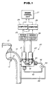
- FIG. 1 With reference to the drawings wherein like numerals refer to like parts in the several views, and in particular to Fig. 1, there is shown a portion of an internal combustion engine 10 for which an NOx concentration measuring apparatus according to the invention is used.
- the engine 10 has an exhaust manifold 12 into which exhaust gases are discharged from the engine. The exhaust gases are then discharged to the atmosphere through an exhaust system (not shown) which conventionally includes a muffler and an exhaust pipe.
- the N0x concentration measuring apparatus is shown as including first and second sensors 21 and 22.
- the first sensor 21 may be taken in the form of a wide-range air/fuel ratio sensor of the type sensitive to oxides of nitrogen (NOx) for measuring the existing oxygen partial pressure. This type of air/fuel ratio sensor has a capacity of resolving NOx only at low oxygen partial pressures.
- the first sensor 21 includes an electrochemical cell containing an oxygen ion conductive electrolyte layer having at least two electrodes disposed on the opposite surfaces thereof for producing a first sensor signal indicative of an oxygen partial pressure of the exhaust gases introduced into the electrochemical cell.
- the second sensor 22 may be taken in the form of a wide-range air/fuel ratio sensor of the type insensitive to oxides of nitrogen (NOx) for measuring the existing oxygen partial pressure. This type of air/fuel ratio sensor cannot resolve NOx regardless of the oxygen partial pressure.
- the second sensor 22 includes an electrochemical cell containing an oxygen ion conductive electrolyte layer having at least two electrodes disposed on the opposite surfaces thereof for producing a second sensor signal indicative of an oxygen partial pressure of the exhaust gases introduced into the electrochemical cell.
- the first sensor 21 converts the concentration of oxygen (O2), carbon monoxide (CO), hydrogen (H2), hydrocarbon (HC), nitrogen monoxide (NO) and other constituents contained in the exhaust gases into a corresponding O2 concentration and it produces a first sensor signal having a value proportional to the converted O2 concentration.
- the second sensor 22 converts the concentration of oxygen (02), carbon monoxide (CO), hydrogen (H2), hydrocarbon (HC), and other constituents except for oxides of nitrogen into a corresponding O2 concentration and it produces a second sensor signal having a value proportional to the converted O2 concentration.
- the second sensor 22 is substantially the same as the first sensor 21 except that it is insensitive to oxides of nitrogen (NOx).
- the first and second sensors 21 and 22 are connected respectively to the first and second sensor control circuits 23 and 24.
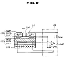
- the second sensor 22 includes at least one pair of sensing and pumping cells 220 and 222 disposed in a parallel-spaced relation with respect to each other within a diffusion chamber 224.
- the sensing cell 220 includes electrodes 220B and 220C disposed on the opposite side surfaces of a solid electrolyte layer 220A.
- the electrodes 220B and 220C of the sensing cell 220 is formed of a material such as platinum or the like insensitive to NOx.
- the pumping cell 222 includes electrodes 222B and 222C disposed on the opposite side surfaces of a solid electrolyte layer 222A. Exhaust gases are introduced through a port 224 into the diffusion chamber 226.
- the numeral 228 designates a heater element.
- the second sensor 22 is connected to a sensor control circuit 24 which includes a differential amplifier 240 having an input connected to the electrode 220C and another input connected to a reference voltage source 242.
- the electrode 220B is grounded.
- the differential amplifier 240 has an output connected to the electrode 222B.
- the electrode 222C is grounded.
- the control circuit 24 controls the current to the heater element 228 and the current Ip to the electrode 222B so as to maintain the voltage between the electrodes 222B and 222C sandwiching the solid electrolyte layer 222A of the pumping cell 222 at a constant value.
- the oxygen concentration is reduced substantially to zero within the diffusion chamber 226 and the exhaust gases charged in the diffusion chamber 226 is maintained substantially at the stoichiometric air/fuel ratio value.
- the current Ip to the electrode 222B has a value corresponding to the O2 concentration.
- the control circuit 23 for the first sensor 21 is substantially similar to the control circuit 24.
- the first and second sensors 21 and 22 are described in detail, and are incorporated herein by reference, in Japanese Patent Application No. 63-122707.
- the first and second sensor signals are fed from the first and second sensor control circuits 23 and 24 to first and second computers 25 and 26, respectively.
- the first computer 25 calculates a value of the air/fuel ratio of the exhaust gases based on the the value of the first sensor signal fed thereto from the first sensor control circuit 23 and transfers the calculated air/fuel ratio value to an engine control unit 27.
- the first computer 25 also transfers the first sensor signal fed thereto from the first sensor control circuit 23 to the second computer 26.
- the second computer 26 calculates an O2 concentration value, which is one-half of the NO concentration, as a function of a difference between the values of the first and second sensor signals.
- the second computer 26 converts the calculated O2 concentration value to a corresponding NO concentration value.
- the NO concentration value is transferred to the engine control unit 27.
- the engine control unit 27 employs the air/fuel ratio value transferred thereto from the first computer 25 and the NO concentration value transferred thereto from the second computer 26 to control the engine 10. Since the first computer 25 transfers the air/fuel ratio value to the engine control unit 27, there is no need for an additional oxygen sensor used in monitoring the air/fuel ratio of the air-fuel mixture supplied to the engine.
- the NOx concentration measuring apparatus includes a sensor retainer 30 having an externally threaded end portion 31 threadedly engaged with an externally threaded opening 16 formed in an exhaust manifold wall 14.
- the sensor retainer 30 has a gas inlet passage 32 which extends through the sensor retainer 30 in the direction of the length of the sensor retainer 30 and in a direction substantially perpendicular to the direction of the exhaust gases flow through the exhaust manifold 12. Since the opening 16 communicates with the exhaust manifold 12, this results in the gas inlet passage 32 opening at its one end into the exhaust manifold 12.
- the other end of the gas inlet passage 32 is connected through a conduit 42 to a suction port of a suction pump 50.
- the suction pump 50 has another suction port connected to a conduit 43 and a discharge port connected to one end of a conduit 44. The other end of the conduit 44 opens into the exhaust manifold 12.
- the sensor retainer 30 is formed with a first pocket 33 for the receipt of the first sensor 21 and a second pocket 34 for the receipt of the second sensor 22.
- the first and second pockets 33 and 34 communicates with each other through the gas inlet passage 32.
- the air inlet passage 32 has a first restricted orifice 35, the area of whose opening determines the degree of reduction of the exhaust gas pressure introduced from the exhaust manifold 12 into the gas inlet passage 32.
- the air inlet passage 32 also has a second restricted orifice 36 located in the air inlet passage 32 somewhere upstream of the first pocket 33. The area of the opening of the second orifice 36 determines the degree of reduction of the gas pressure introduced into the first pocket 33.
- a branched passage 37 opens at its one end into the gas inlet passage 32 somewhere between the first and second orifices 35 and 36 and it is connected at the other end thereof through the conduit 43 to the suction pump 50 (Fig. 1).
- the numeral 21A designates a louver door provided upstream of the diffusion chamber of the first sensor 21, and the numeral 22A designates a louver door provided upstream of the diffusion chamber of the second sensor 22.
- the operation is as follows.
- exhaust gases are introduced from the exhaust manifold 12 through the first orifice 31 into the gas inlet passage 32.
- the first orifice 31 provides an exhaust gas pressure reduction ranging from about 50 mmHg to about 100 mmHg with respect to the exhaust manifold pressure.
- Most of the exhaust gases are sucked through the branched passage 37 and the conduit 43 to the suction pump 50.
- some of the exhaust gases are introduced through the second orifice 36 into the diffusion chamber of the first sensor 21 placed in the first pocket 33.
- the second orifice 36 provides an additional exhaust gas pressure reduction ranging from about 200 mmHg to 400 mmHg.
- the exhaust gas are then introduced into the diffusion chamber of the second sensor 22 placed in the second pocket 34 and hence through the conduit 42 to the suction pump 50.
- the suction pump 50 discharges the exhaust gases, which are introduced therein from the conduits 42 and 43, through the conduit 44 into the exhaust manifold 12.
- the first and second orifices 35 and 36 can reduce the width of the range in which the pressure of the exhaust gases introduced into the diffusion chambers of the first and second sensors 21 and 22 to several mmHgs when the width of the range in which the exhaust manifold pressure varies is several hundreds of mmHg.
- the first and second orifices 35 and 36 are effective to prevent momentary fluctuations in the exhaust manifold pressure from affecting the accuracy of measurement of the first and second sensors 21 and 22.
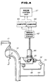
- Fig. 4 there is shown a second embodiment of the NOx concentration measuring apparatus of the invention.
- the arrangement of Fig. 4 utilizes a number of components previously described, and like reference numerals in Fig. 4 indicate like parts as described with reference to Fig. 1.
- the chief difference between Fig. 4 and the first described embodiment is that the measuring apparatus includes a sensor 60 having two sensors incorporated in a single casing. These sensors, which are substantially the same as the first and second sensors 21 and 22 of Fig. 1, are connected to a sensor control circuit 62.
- the sensor control circuit 62 produces a first sensor signal having a value proportional to the sensed O2 concentration, as described in connection with the first sensor 21, and a second sensor signal having a value proportional to the sensed O2 concentration, as described in connection with the second sensor 22.
- the first and second sensor signals are fed to a first computer 64.
- the first computer 64 calculates an O2 concentration value, which is one-half of the NO concentration, as a function of a difference between the values of the first and second sensor signals.
- the first computer 64 converts the calculated O2 concentration value to a corresponding NO concentration value and transfers the NO concentration value to the engine control unit 27.
- the first computer 64 also transfers the first sensor signal to a second computer 66 which calculates a value of the air/fuel ratio of the exhaust gases based on the value of the first sensor signal transferred thereto from the first computer 64 and transfers the calculated air/fuel ratio value to the engine control unit 27.
- the engine control unit 27 employs the NO concentration value transferred thereto from the first computer 64 and the air/fuel ratio value transferred thereto from the second computer 66 to control the engine 10. Since the second computer 66 transfers the air/fuel ratio value to the engine control unit 27, there is no need for an additional oxygen sensor used in monitoring the air/fuel ratio of the air-fuel mixture supplied to the engine. Since the first and second sensors included in the sensor 60 have the same characteristics, it is possible to improve the accuracy of measurement of the NOx measuring apparatus. Furthermore, the measuring apparatus of this embodiment consumes less space for equipment than the measuring apparatus of the first described embodiment.
Landscapes
- Chemical & Material Sciences (AREA)
- Life Sciences & Earth Sciences (AREA)
- Health & Medical Sciences (AREA)
- Engineering & Computer Science (AREA)
- Analytical Chemistry (AREA)
- General Physics & Mathematics (AREA)
- Pathology (AREA)
- Physics & Mathematics (AREA)
- Immunology (AREA)
- Biochemistry (AREA)
- General Health & Medical Sciences (AREA)
- Combustion & Propulsion (AREA)
- Food Science & Technology (AREA)
- Medicinal Chemistry (AREA)
- Molecular Biology (AREA)
- Chemical Kinetics & Catalysis (AREA)
- Electrochemistry (AREA)
- Measuring Oxygen Concentration In Cells (AREA)
- Sampling And Sample Adjustment (AREA)
Claims (2)
- Appareil pour mesurer la concentration de NOx de gaz d'échappement évacués dans un collecteur d'échappement (12) par un moteur à combustion interne (10), l'appareil comprenant :
un premier capteur (21) réagissant à des oxydes d'azote pour résoudre des oxydes d'azote à des faibles pressions partielles d'oxygène, le premier capteur (21) incluant une cellule électrochimique contenant une couche d'électrolyte conductrice d'ions d'oxygène ayant au moins deux électrodes disposées sur les surfaces opposées de celle-ci pour fournir un premier signal de capteur indiquant une pression partielle d'oxygène des gaz d'échappement introduite dans la cellule électrochimique,
un deuxième capteur (22) ne réagissant pas aux oxydes d'azote, le deuxième capteur (22) incluant une cellule électrochimique contenant une couche d'électrolyte conductrice d'ions d'oxygène ayant au moins deux électrodes disposées sur les surfaces opposées de celle-ci pour fournir un deuxième signal de capteur indiquant une pression partielle d'oxygène des gaz d'échappement introduits dans la cellule électrochimique, et
des moyens (23, 24, 25, 26, 27, 64, 66) connectés aux premier et deuxième capteurs pour calculer une concentration de NOx sur la base des premier et deuxième signaux de capteur, caractérisé par un premier passage (32) s'ouvrant dans le collecteur d'échappement (12) pour introduire des gaz d'échappement dans les cellules électrochimiques des premier et deuxième capteurs (21, 22),
des premier et deuxième orifices limités (35, 36) prévus dans le premier passage (32) en amont des premier et deuxième capteurs (21, 22) pour limiter un flux de gaz vers les premier et deuxième capteurs (21, 22),
un deuxième passage (37) connecté au premier passage (32) entre les premier et deuxième orifices (35, 36) ; et
une pompe d'aspiration (50) connectée au premier passage (32) en aval des premier et deuxième capteurs (21, 22) pour produire un vide d'aspiration dans le premier passage (32), la pompe d'aspiration (50) étant connectée au deuxième passage (37) pour produire un vide d'aspiration dans le deuxième passage (37). - Appareil selon la revendication 1, dans lequel le moyen de calcul (23, 24, 25, 26, 27, 64, 66) comprend un moyen (66) pour calculer une valeur de rapport air/combustible pour un mélange air/combustible fourni au moteur (10) sur la base du premier signal de capteur.
Applications Claiming Priority (2)
| Application Number | Priority Date | Filing Date | Title |
|---|---|---|---|
| JP1140016A JPH034157A (ja) | 1989-06-01 | 1989-06-01 | 窒素酸化物濃度の計測装置 |
| JP140016/89 | 1989-06-01 |
Publications (3)
| Publication Number | Publication Date |
|---|---|
| EP0400627A2 EP0400627A2 (fr) | 1990-12-05 |
| EP0400627A3 EP0400627A3 (fr) | 1991-04-03 |
| EP0400627B1 true EP0400627B1 (fr) | 1995-05-10 |
Family
ID=15258976
Family Applications (1)
| Application Number | Title | Priority Date | Filing Date |
|---|---|---|---|
| EP90110296A Expired - Lifetime EP0400627B1 (fr) | 1989-06-01 | 1990-05-30 | Appareil pour déterminer la concentration de NOx |
Country Status (4)
| Country | Link |
|---|---|
| US (1) | US4988428A (fr) |
| EP (1) | EP0400627B1 (fr) |
| JP (1) | JPH034157A (fr) |
| DE (1) | DE69019231T2 (fr) |
Families Citing this family (14)
| Publication number | Priority date | Publication date | Assignee | Title |
|---|---|---|---|---|
| JP2863229B2 (ja) * | 1989-12-22 | 1999-03-03 | 三菱電機株式会社 | 内燃機関の空燃比制御装置 |
| DE4004086A1 (de) * | 1990-02-10 | 1991-08-14 | Bosch Gmbh Robert | System zur steuerung bzw. regelung einer brennkraftmaschine in einem kraftfahrzeug |
| US5373724A (en) * | 1992-06-02 | 1994-12-20 | Trw Inc. | Method of sensing a gas concentration |
| US5329764A (en) * | 1993-01-11 | 1994-07-19 | Ford Motor Company | Air/fuel feedback control system |
| US5341643A (en) * | 1993-04-05 | 1994-08-30 | Ford Motor Company | Feedback control system |
| DE4311985C2 (de) * | 1993-04-07 | 1996-02-08 | Mannesmann Ag | Festelektrolyt-Sensor |
| US5397442A (en) * | 1994-03-09 | 1995-03-14 | Gas Research Institute | Sensor and method for accurately measuring concentrations of oxide compounds in gas mixtures |
| US5554269A (en) * | 1995-04-11 | 1996-09-10 | Gas Research Institute | Nox sensor using electrochemical reactions and differential pulse voltammetry (DPV) |
| JP3796333B2 (ja) * | 1996-12-20 | 2006-07-12 | 日本碍子株式会社 | ガスセンサ |
| JP3664558B2 (ja) * | 1996-12-20 | 2005-06-29 | 日本碍子株式会社 | ガスセンサ |
| JP3701124B2 (ja) | 1998-07-08 | 2005-09-28 | 日本碍子株式会社 | ガスセンサ及び窒素酸化物センサ |
| US8955659B2 (en) * | 2011-03-31 | 2015-02-17 | Honda Motor Co., Ltd. | Internal combustion engine and supplying oil path structure for hydraulic clutch in internal combustion engine |
| US9255542B2 (en) * | 2013-02-04 | 2016-02-09 | Ford Global Technologies, Llc | System and method for compensating biodiesel fuel |
| FR3037655B1 (fr) * | 2015-06-18 | 2017-07-28 | Armines - Ass Pour La Rech Et Le Dev Des Methodes Et Processus Ind | Capteur nox a filtre catalytique et polarisation |
Family Cites Families (7)
| Publication number | Priority date | Publication date | Assignee | Title |
|---|---|---|---|---|
| US4115235A (en) * | 1976-11-08 | 1978-09-19 | Thermo-Lab Instruments, Inc. | Apparatus for conveying a gas sample through an analyzer chamber |
| US4446748A (en) * | 1981-11-27 | 1984-05-08 | Precision Machine Products, Inc. | Proportional flow sampler |
| GB2135462A (en) * | 1983-02-22 | 1984-08-30 | Autotech Developments Limited | Monitoring gas composition |
| DE3509360A1 (de) * | 1985-02-14 | 1986-08-14 | Bbc Brown Boveri & Cie | Verfahren zur messung des sauerstoffgehalts im abgas von brennkraftmaschinen |
| JPH0672861B2 (ja) * | 1986-08-04 | 1994-09-14 | 日本碍子株式会社 | NOxセンサ |
| JPH0820410B2 (ja) * | 1988-02-19 | 1996-03-04 | 日産自動車株式会社 | 窒素酸化物濃度の計測装置 |
| JP2636883B2 (ja) * | 1988-04-30 | 1997-07-30 | 日本碍子株式会社 | NOx濃度測定装置 |
-
1989
- 1989-06-01 JP JP1140016A patent/JPH034157A/ja active Pending
-
1990
- 1990-05-15 US US07/523,459 patent/US4988428A/en not_active Expired - Fee Related
- 1990-05-30 EP EP90110296A patent/EP0400627B1/fr not_active Expired - Lifetime
- 1990-05-30 DE DE69019231T patent/DE69019231T2/de not_active Expired - Fee Related
Also Published As
| Publication number | Publication date |
|---|---|
| JPH034157A (ja) | 1991-01-10 |
| EP0400627A3 (fr) | 1991-04-03 |
| EP0400627A2 (fr) | 1990-12-05 |
| US4988428A (en) | 1991-01-29 |
| DE69019231D1 (de) | 1995-06-14 |
| DE69019231T2 (de) | 1995-09-07 |
Similar Documents
| Publication | Publication Date | Title |
|---|---|---|
| EP0999442B1 (fr) | Dispositif de mesure de concentration de gaz avec compensation d'erreurs du signal de sortie | |
| US4988428A (en) | NOx concentration measuring apparatus | |
| EP1669750B1 (fr) | Capteur de NOx à électrolyte solide avec un espace tampon en amont d'une cellule de pompage | |
| US4884066A (en) | Deterioration detector system for catalyst in use for emission gas purifier | |
| US4614175A (en) | Engine exhaust gas recirculation control system | |
| US5357750A (en) | Method for detecting deterioration of catalyst and measuring conversion efficiency thereof with an air/fuel ratio sensor | |
| US6348141B1 (en) | Gas sensor | |
| US7981265B2 (en) | Gas concentration measuring apparatus designed to enhance measurement accuracy in desired range | |
| US20020104758A1 (en) | Structure of gas sensor element designed to minimize error of sensor output | |
| US6284112B1 (en) | Gas sensor | |
| JPH021543A (ja) | 窒素酸化物濃度の計測装置 | |
| US6495027B1 (en) | Electrochemical gas sensor and method for determining gas components | |
| US11378542B2 (en) | Gas sensor | |
| US4782690A (en) | Air/fuel ratio detecting apparatus, and method of detecting normal and abnormal conditions of the sensor | |
| US6740217B2 (en) | Structure of gas sensor designed to minimize error of sensor output | |
| US8721856B2 (en) | Gas sensor control system ensuring increased measurement accuracy | |
| US4787966A (en) | Oxygen concentration sensor for an internal combustion engine | |
| EP0126590B1 (fr) | Capteur du rapport air-combustible d'un moteur | |
| JPH10253585A (ja) | ガスセンサ | |
| US20010025789A1 (en) | Multilayered gas sensing element employable in an exhaust system of an internal combustion engine | |
| US20030062904A1 (en) | Error minimizing structure of gas sensor | |
| JPH03272450A (ja) | 窒素酸化物濃度の計測装置 | |
| JPH0373840A (ja) | 窒素酸化物排出量測定装置 | |
| JPS63279159A (ja) | ガス検出装置 | |
| JPS60111953A (ja) | 機関の空燃比センサ |
Legal Events
| Date | Code | Title | Description |
|---|---|---|---|
| PUAI | Public reference made under article 153(3) epc to a published international application that has entered the european phase |
Free format text: ORIGINAL CODE: 0009012 |
|
| 17P | Request for examination filed |
Effective date: 19900530 |
|
| AK | Designated contracting states |
Kind code of ref document: A2 Designated state(s): DE GB |
|
| PUAL | Search report despatched |
Free format text: ORIGINAL CODE: 0009013 |
|
| AK | Designated contracting states |
Kind code of ref document: A3 Designated state(s): DE GB |
|
| 17Q | First examination report despatched |
Effective date: 19930714 |
|
| GRAA | (expected) grant |
Free format text: ORIGINAL CODE: 0009210 |
|
| AK | Designated contracting states |
Kind code of ref document: B1 Designated state(s): DE GB |
|
| REF | Corresponds to: |
Ref document number: 69019231 Country of ref document: DE Date of ref document: 19950614 |
|
| PLBE | No opposition filed within time limit |
Free format text: ORIGINAL CODE: 0009261 |
|
| STAA | Information on the status of an ep patent application or granted ep patent |
Free format text: STATUS: NO OPPOSITION FILED WITHIN TIME LIMIT |
|
| 26N | No opposition filed | ||
| PGFP | Annual fee paid to national office [announced via postgrant information from national office to epo] |
Ref country code: GB Payment date: 19960521 Year of fee payment: 7 |
|
| PGFP | Annual fee paid to national office [announced via postgrant information from national office to epo] |
Ref country code: DE Payment date: 19960528 Year of fee payment: 7 |
|
| PG25 | Lapsed in a contracting state [announced via postgrant information from national office to epo] |
Ref country code: GB Effective date: 19970530 |
|
| GBPC | Gb: european patent ceased through non-payment of renewal fee |
Effective date: 19970530 |
|
| PG25 | Lapsed in a contracting state [announced via postgrant information from national office to epo] |
Ref country code: DE Free format text: LAPSE BECAUSE OF NON-PAYMENT OF DUE FEES Effective date: 19980203 |