EP0400639B1 - Système pour l'enrichissement d'une substance à tester en vue d'applications spectroscopiques en analyse du type à injection - Google Patents
Système pour l'enrichissement d'une substance à tester en vue d'applications spectroscopiques en analyse du type à injection Download PDFInfo
- Publication number
- EP0400639B1 EP0400639B1 EP90110356A EP90110356A EP0400639B1 EP 0400639 B1 EP0400639 B1 EP 0400639B1 EP 90110356 A EP90110356 A EP 90110356A EP 90110356 A EP90110356 A EP 90110356A EP 0400639 B1 EP0400639 B1 EP 0400639B1
- Authority
- EP
- European Patent Office
- Prior art keywords
- sample
- valve
- ion exchange
- connection
- liquid
- Prior art date
- Legal status (The legal status is an assumption and is not a legal conclusion. Google has not performed a legal analysis and makes no representation as to the accuracy of the status listed.)
- Expired - Lifetime
Links
- 238000004401 flow injection analysis Methods 0.000 title claims description 13
- 239000000126 substance Substances 0.000 title claims description 6
- 239000000523 sample Substances 0.000 title description 76
- 239000007788 liquid Substances 0.000 claims description 51
- 238000005342 ion exchange Methods 0.000 claims description 44
- 238000010521 absorption reaction Methods 0.000 claims description 20
- 238000006073 displacement reaction Methods 0.000 claims description 11
- 239000000872 buffer Substances 0.000 claims description 10
- 230000000717 retained effect Effects 0.000 claims description 9
- 238000000889 atomisation Methods 0.000 claims description 8
- 239000007853 buffer solution Substances 0.000 claims description 8
- 238000004458 analytical method Methods 0.000 claims description 7
- 238000005086 pumping Methods 0.000 description 27
- XLYOFNOQVPJJNP-UHFFFAOYSA-N water Substances O XLYOFNOQVPJJNP-UHFFFAOYSA-N 0.000 description 11
- 230000002572 peristaltic effect Effects 0.000 description 6
- 239000002699 waste material Substances 0.000 description 6
- VEXZGXHMUGYJMC-UHFFFAOYSA-N Hydrochloric acid Chemical compound Cl VEXZGXHMUGYJMC-UHFFFAOYSA-N 0.000 description 4
- 238000000034 method Methods 0.000 description 4
- 239000000203 mixture Substances 0.000 description 4
- 238000001479 atomic absorption spectroscopy Methods 0.000 description 3
- 238000011010 flushing procedure Methods 0.000 description 3
- 238000002347 injection Methods 0.000 description 3
- 239000007924 injection Substances 0.000 description 3
- 230000002452 interceptive effect Effects 0.000 description 3
- 239000012488 sample solution Substances 0.000 description 3
- USFZMSVCRYTOJT-UHFFFAOYSA-N Ammonium acetate Chemical compound N.CC(O)=O USFZMSVCRYTOJT-UHFFFAOYSA-N 0.000 description 2
- 239000005695 Ammonium acetate Substances 0.000 description 2
- 229940043376 ammonium acetate Drugs 0.000 description 2
- 235000019257 ammonium acetate Nutrition 0.000 description 2
- 239000000470 constituent Substances 0.000 description 2
- 239000003480 eluent Substances 0.000 description 2
- 239000004009 herbicide Substances 0.000 description 2
- 238000005259 measurement Methods 0.000 description 2
- GRYLNZFGIOXLOG-UHFFFAOYSA-N Nitric acid Chemical compound O[N+]([O-])=O GRYLNZFGIOXLOG-UHFFFAOYSA-N 0.000 description 1
- 150000001450 anions Chemical class 0.000 description 1
- 239000012490 blank solution Substances 0.000 description 1
- 239000012482 calibration solution Substances 0.000 description 1
- 239000003795 chemical substances by application Substances 0.000 description 1
- 238000004587 chromatography analysis Methods 0.000 description 1
- 239000012141 concentrate Substances 0.000 description 1
- 239000008367 deionised water Substances 0.000 description 1
- 229910021641 deionized water Inorganic materials 0.000 description 1
- 238000001514 detection method Methods 0.000 description 1
- 230000000694 effects Effects 0.000 description 1
- 238000004128 high performance liquid chromatography Methods 0.000 description 1
- 239000011159 matrix material Substances 0.000 description 1
- 229910017604 nitric acid Inorganic materials 0.000 description 1
- QIIPQYDSKRYMFG-UHFFFAOYSA-N phenyl hydrogen carbonate Chemical compound OC(=O)OC1=CC=CC=C1 QIIPQYDSKRYMFG-UHFFFAOYSA-N 0.000 description 1
- 238000004094 preconcentration Methods 0.000 description 1
- 239000012487 rinsing solution Substances 0.000 description 1
- 230000001360 synchronised effect Effects 0.000 description 1
Images
Classifications
-
- G—PHYSICS
- G01—MEASURING; TESTING
- G01N—INVESTIGATING OR ANALYSING MATERIALS BY DETERMINING THEIR CHEMICAL OR PHYSICAL PROPERTIES
- G01N1/00—Sampling; Preparing specimens for investigation
- G01N1/28—Preparing specimens for investigation including physical details of (bio-)chemical methods covered elsewhere, e.g. G01N33/50, C12Q
- G01N1/40—Concentrating samples
- G01N1/405—Concentrating samples by adsorption or absorption
-
- G—PHYSICS
- G01—MEASURING; TESTING
- G01N—INVESTIGATING OR ANALYSING MATERIALS BY DETERMINING THEIR CHEMICAL OR PHYSICAL PROPERTIES
- G01N30/00—Investigating or analysing materials by separation into components using adsorption, absorption or similar phenomena or using ion-exchange, e.g. chromatography or field flow fractionation
- G01N30/96—Investigating or analysing materials by separation into components using adsorption, absorption or similar phenomena or using ion-exchange, e.g. chromatography or field flow fractionation using ion-exchange
-
- G—PHYSICS
- G01—MEASURING; TESTING
- G01N—INVESTIGATING OR ANALYSING MATERIALS BY DETERMINING THEIR CHEMICAL OR PHYSICAL PROPERTIES
- G01N35/00—Automatic analysis not limited to methods or materials provided for in any single one of groups G01N1/00 - G01N33/00; Handling materials therefor
- G01N35/08—Automatic analysis not limited to methods or materials provided for in any single one of groups G01N1/00 - G01N33/00; Handling materials therefor using a stream of discrete samples flowing along a tube system, e.g. flow injection analysis
- G01N35/085—Flow Injection Analysis
Definitions
- a hose pump conveys water in parallel hose lines, a buffer liquid in the form of ammonium acetate and an eluting liquid in the form of nitric acid.
- An injection valve is arranged in the hose line into which the water is conveyed.
- the injection valve contains a through-channel and a sample loop, which can optionally be switched into the flow in the hose line. When the through-channel is switched into the hose line, a flow of sample liquid is passed through the sample loop, so that the sample loop is filled with sample liquid.
- the sample loop filled with sample liquid is switched into the hose line leading the water flow, so that the Sample liquid is taken away from the water flow.
- the water or the sample liquid are mixed with the buffer liquid and flow in a first valve position of a valve arrangement through an ion exchange column, from a first end of the ion exchange column to a second end. The second end is connected to a waste outlet.
- the eluting liquid flows to an atomizer and is sprayed into the flame of an atomic absorption spectrometer.
- the sample is now enriched in the ion exchange column.
- the valve arrangement is then switched to a second valve position.
- the water and ammonium acetate hose lines are connected to the waste outlet.
- the second end of the ion exchange column is connected to the hose line carrying the eluent liquid.
- the first end of the ion exchange column is connected to the atomizer of the atomic absorption spectrometer.
- the eluting liquid flows through the ion exchange column in counterflow to the previous flow direction and elutes the enriched elements to be determined in the atomizer and thus in the burner of the atomic absorption spectrometer.
- a first peristaltic pump each deliver a first sample liquid with an associated buffer liquid and a second sample liquid with an associated buffer liquid.
- the sample liquids are mixed with the associated buffer liquids in tube coils, which are connected downstream of the peristaltic pump.
- the so The sample and buffer liquid obtained are passed to a first valve. In a first valve position of the first valve, the sample and buffer liquids are directed to a first end of an associated ion exchange column.
- the other, second ends of the ion exchange columns are each connected to a waste outlet.
- the two ion exchange columns are then loaded in parallel with sample liquid, the sample is enriched in the columns.
- a second peristaltic pump conveys an eluting liquid and water.
- the water In the first position of the valve, the water is directed onto the atomizer of a plasma torch.
- the eluting liquid is connected to a waste outlet in this first position of the valve.
- the valve directs the eluting liquid to the second end of one of the ion exchange columns, the first end of which is then connected to the atomizer.
- the ion exchange column acted upon by the eluting liquid is selected by a changeover valve.
- the analysis time can be halved.
- water is directed onto the atomizer while the ion exchange columns are being loaded. The water rinses the atomizer and stabilizes the plasma.
- the eluting liquid with the eluted, enriched sample is passed to an atomizer which atomizes the liquid into a flame of an atomic absorption spectrometer.
- DE-C-29 00 066 describes a sampler in which samples are arranged in sample vessels on a turntable.
- a suction tube sucks in sample liquid from the sample vessels and enters them into an oven provided with a sample entry opening for the electrothermal atomization of the sample.
- a measuring beam of light from an atomic absorption spectrometer passes through the furnace.
- the invention has for its object to increase the detection limits in atomic absorption spectroscopy.
- the element sought is thus concentrated on the ion exchange column. Interfering components of the sample are not held on the ion exchange column and are therefore eliminated for the atomic absorption measurement. This is done in a flow injection arrangement, so closed off from the environment. However, the sample components retained on the ion exchange column are not eluted in the atomizer of a burner as in the known arrangements and are also not passed into an open sample vessel, but instead go directly into a metering capillary which can be inserted into an oven of the atomic absorption spectrometer.
- the sought-after constituents retained on the ion exchange column can be eluted with an amount of eluting liquid which is taken up by the metering capillary, the volume of the metering capillary again being no greater than the capacity of the oven for sample liquid.
- the metering capillary is simultaneously introduced into a sample entry opening of the oven and the eluate contained therein is pressed into the oven by the displacement pressure medium.
- the first pumping means are switched on during a first operating phase and switched off during a subsequent second operating phase.
- the second pumping means are switched off during the first operating phase and switched on during the second operating phase.
- the valve means can be switched from the first valve position to the second valve position at a point in time within the second operating phase.
- the displacement pressure medium is conveyed by the first pumping means.
- the displacement pressure medium is advantageously a gas, for example air.
- a flushing liquid can be conveyed into a collecting line by means of the second pumping means, via which line during the first operating phase Sample and buffer solution is passed from the first pumping means to the valve means and which is connected to a drain outlet in the second valve position.
- a sample connection and a connection for buffer solution are brought together on the output side from the first pump means to form a collecting line which is connected to a collecting line connection of the valve means.
- a flushing agent connection is connected to the collecting line via the second pumping means and a connecting line.
- the manifold port is connected to the first end of the ion exchange column in the first valve position and to a drain outlet in the second valve position. is.
- the analyzer is an atomic absorption spectrometer with an oven for electrothermal atomization of the sample.
- the dosing capillary for dispensing the sample can be inserted into a sample entry opening of the furnace.
- the volume of the dosing capillary is not greater than the absorption capacity of the furnace.
- the first and second pump means are each formed by a peristaltic pump.
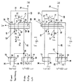
- 10 denotes first pumping means in the form of a peristaltic pump and 12 second means of pumping, likewise in the form of a peristaltic pump.
- the hose pump of the first pumping means 10 contains three hose lines 14, 16 and 18.
- the hose line 14 is connected to a sample inlet 20.
- the sample inlet 20 can be connected, for example, to a metering tube, which draws the sample from a sample vessel onto a turntable or a blank or calibration solution.
- the hose line 16 is connected to a buffer inlet 22, via which a buffer solution can be sucked in.
- the hose line 18 is with connected to an inlet 24, via which a displacement pressure medium is sucked in.
- the displacement pressure medium in the preferred embodiment is simply air.
- the hose lines 14 and 16 of the pumping means 10 are brought together at a union point 26.
- a manifold 28 goes from the union point 26 to the valve means 30.
- the hose pump of the second pumping means 12 contains two hose lines 32 and 34.
- the hose line 32 is connected to a connection 36, via which an eluting liquid (eluent) can be drawn in, for example hydrochloric acid.
- the hose line 34 is connected to an inlet 38. A rinsing solution, for example deionized water, can be sucked in via the inlet 38.
- the hose line 34 is also connected to the collecting line 28 at the union point 26.
- the valve means 30 are shown here as a slide valve and contain a stationary valve member 40 and a valve member 42 movable between a first valve position (FIG. 1) and a second valve position (FIG. 2).
- the stationary valve member 40 has a first connection 44, a second one Port 46, a third port 48 and a fourth port 50.
- the movable valve member has a fifth port 52, a sixth port 54, a seventh port 56, an eighth port 58 and a ninth port 60.
- the first connection 44 is connected to the fifth connection 52.
- the second connection 46 is connected to the sixth connection 54.
- the third connection 48 is connected to the seventh connection 56.
- the fourth connection 50 is connected to the eighth connection 58.
- the first connection 44 is connected to the sixth connection 54.
- the second connection 46 is connected to the seventh connection 56.
- the third connection 48 is connected to the eighth connection 58.
- the fourth connection 50 is connected to the ninth connection 60.
- the hose line 32 of the second pumping means 12 is led to the first connection 44 of the valve means 30.
- the second port 46 is connected to a drain outlet 62.
- a metering capillary 64 is connected to the third connection 48.
- the fourth connection 50 of the valve means 30 is connected to the manifold 28.
- the fifth connection 52 and the ninth connection 60 are connected to a drain connection 70 via lines 66 and 68.
- An ion exchange column 72 lies between the sixth connection 54 and the eighth connection 58.
- the ion exchange column 72 has a first end 74 which is connected to the eighth connection 58 and a second end 76 which is connected to the sixth connection 54 of the valve means 30 .
- the ion exchange column 72 tapers from the second end 76 to the first end 74.
- the seventh connection 56 of the valve means 30 is connected to the hose line 18 of the first pump means 10.
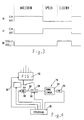
- An atomic absorption spectrometer 78 is shown schematically in FIG.
- the atomic absorption spectrometer 78 has a hollow cathode lamp 80, from which a measuring light bundle 82 originates.
- the measuring light beam passes through a monochromator 84 and falls on a detector 86.
- a furnace 88 is provided for atomizing the sample and can be heated to atomization temperature by passing electric current through it.
- the measuring light bundle 82 passes through the longitudinal bore of the tubular furnace 88 through it. With 90 a sample input opening of the furnace 88 is designated.
- the dosing capillary 64 can be inserted into the sample entry opening of the furnace 88 by means of a servomotor 92, as is indicated by the dashed line 94.
- the flow injection system as a whole, which is shown in FIGS. 1 and 2, is represented by a block 96 in FIG. The entire arrangement can be controlled by a control unit 98 for executing a specific program.
- FIG. 3 shows the states of the pumping means 10 and 12 and the valve means 30 in the different operating phases.
- the pumping means 10 are switched on and the pumping means 12 are switched off.
- the valve means 30 are in the valve position "1". This is the "enrichment” state shown in Fig.1.
- the pumping means 10 are switched off and the pumping means 12 are switched on.
- the valve means 30 are still in the valve position "1”.
- the “Rinse” function then results.
- the valve means 30 are then switched to the "2" position.
- the state shown in Figure 2 results. This is the "elute” function.
- the various states are controlled by the control unit 98 and suitably synchronized with the function of the atomic absorption spectrometer 78, the furnace 88 and the servomotor 92.
- valve means 30 are in the first valve position. They are running first pump means 10, while the second pump means 12 are stationary. As a result, sample is sucked in via inlet 20 and hose line 14 and buffer solution via inlet 22 and hose line 16. Sample and buffer solution are brought together at the union point 26 and passed via the manifold 28 to the fourth connection of the valve means 30. In the first valve position, the mixture of sample and buffer solution thus obtained is passed via connection 58 of the valve means to the first end 74 of the ion exchange column 72. The mixture flows through the ion exchange column 72 and via its second end 76 and the connections 54 and 46 of the valve means 30 to the drain connection 62.
- the ion exchange column 72 When flowing through the ion exchange column 72, sought components of the sample are retained on the ion exchange column 72 and enriched there. Interfering constituents (matrix) flow predominantly through the ion exchange column 72 and through the drain connection. As a result, the components sought are enriched. On the other hand, disruptive components are eliminated. These interfering components can therefore no longer interfere with the subsequent measurement in the atomic absorption spectrometer. The amount of the substance to be atomized is also considerably reduced, based on the amount of the components sought.
- the purpose of the buffer solution is to produce such a composition of the mixture, for example a pH such that the components sought are actually retained on the ion exchange column 72.
- the conically tapering shape of the ion exchange column 72 has the effect that the components of the sample sought are initially retained in the tip of the ion exchange column 72. They are very spatially concentrated there and can therefore, as will be explained later, be eluted very quickly and in a very tight "package".
- the sought-after components from a sample are enriched in the manner described
- the sought-after components from the previous sample which were eluted into the metering capillary 64 in a manner to be described below, are simultaneously released into the furnace 88.
- the free end of the dosing capillary 64 is inserted through the sample entry opening 90 into the furnace 88.
- the air sucked in by the first pump means via the inlet 24 and conveyed in the hose line 18 is pressed via connection 56 and connection 48 of the valve means into the rear end of the metering capillary 64 and displaces the eluted sample components contained therein. These are pressed into the furnace 88.
- the metering capillary is then pivoted out of the oven 88.
- the furnace is heated to the atomization temperature.
- the first pump means 10 are then stopped and the second pump means 12 are switched on for this purpose.
- the valve means 30 remain in their first position of Fig.1.
- a rinsing liquid is now passed from inlet 38 via hose line 34, connection point 26, collecting line 28, connection 50 and connection 58 from the first end 74 to the second end 76 through the ion exchange column 72 and via connection 54 and connection 46 to the outlet connection 62.
- the system is thus cleaned of the remnants of the sample.
- the components of the sample retained on the ion exchange column 72 are not influenced by this rinsing process. This is indicated in Figure 3 by the "rinse" function.
- the eluting liquid from the inlet 36 is passed to the outlet connection 70.
- valve means 30 are then switched to the second valve position.
- the second pumping means 12 continue to run while the first pumping means 10 are stationary. This is shown in Fig.2. In Figure 3 this corresponds to the "elute" function.
- eluting liquid e.g. Hydrochloric acid
- the sought-after components of the sample retained in the ion exchange column 72 are eluted and transported into the metering capillary 64 with the eluting liquid.
- a quantity of eluting liquid which can be completely absorbed by the metering capillary 64 is sufficient for this.
- the volume of the dosing capillary 64 is in turn not greater than the absorption capacity of the furnace 88 for sample liquid.
- the eluted components with the eluting liquid are dosed from the dosing capillary 64 during the enrichment of the next sample in the manner described above into the furnace 88.
- the flushing liquid from the inlet 38 flows from the hose line 38 via the collecting line 28 and via the connections 50 and 60 of the valve means 30 to the outlet connection 70.
- the collecting line is further flushed.
Landscapes
- General Health & Medical Sciences (AREA)
- Health & Medical Sciences (AREA)
- Life Sciences & Earth Sciences (AREA)
- Chemical & Material Sciences (AREA)
- Analytical Chemistry (AREA)
- Biochemistry (AREA)
- Physics & Mathematics (AREA)
- General Physics & Mathematics (AREA)
- Immunology (AREA)
- Pathology (AREA)
- Investigating Or Analysing Materials By Optical Means (AREA)
- Sampling And Sample Adjustment (AREA)
- Automatic Analysis And Handling Materials Therefor (AREA)
Claims (8)
- Système pour enrichir une substance à analyser par voie spectroscopique lors d'une analyse par injection dans l'écoulement, comprenant :a) des premiers moyens de pompage (10) destinés à refouler un liquide à analyser (S) et un liquide tampon (B) dans une conduite collectrice (28),b) des deuxièmes moyens de pompage (12) destinés à refouler un liquide éluant dans une conduite (44),c) une colonne échangeuse d'ions (72) qui est pourvue d'une première extrémité (74) et d'une deuxième extrémité (76), par laquelle les éléments à déterminer sont retenus et à partir de laquelle les éléments à déterminer peuvent être élués par le liquide éluant,d) des moyens (64) pour introduire un échantillon dans un appareil d'analyse (78), et :e) des moyens à valve (30) par lesquels :- dans une première position de la valve, la première extrémité (74) de la colonne échangeuse d'ions (72) est reliée à la conduite collectrice (28), la deuxième extrémité (76) de la colonne échangeuse d'ions (72) est reliée à une première sortie d'évacuation (62), et les moyens (64) pour introduire un échantillon dans l'appareil d'analyse (78) sont reliés à une source (24) d'un agent de déplacement sous pression (L),- dans une deuxième position de la valve, la deuxième extrémité (76) de la colonne échangeuse d'ions (72) est reliée à la conduite (44), sa première extrémité (74) est reliée aux moyens (64) pour introduire un échantillon dans un appareil d'analyse spectroscopique (78), et la conduite collectrice (28) est reliée à une deuxième sortie d'évacuation (70),caractérisé par le fait que :f) les premiers moyens de pompage (10) sont destinés à refouler l'agent de déplacement sous pression (L),g) les deuxièmes moyens de pompage sont destinés à refouler un liquide de rinçage (E2) dans la conduite collectrice (28),h) il est prévu un dispositif de commande (98) qui est destiné à commander les premiers moyens de pompage (10) et les deuxièmes moyens de pompage (12) d'une manière telle que les premiers moyens de pompage (10) soient en marche pendant une première phase de fonctionnement et arrêtés pendant une deuxième phase de fonctionnement qui suit et que les deuxièmes moyens de pompage (12) soient arrêtés pendant la première phase de fonctionnement et en marche pendant la deuxième phase de fonctionnement,i) il est prévu un dispositif de commande (98) qui est destiné à commander les moyens à valve (30) d'une manière telle que les moyens à valve (30) puissent passer de la première position de la valve à la deuxième position de la valve à un instant situé après le début de la deuxième phase de fonctionnement et à l'intérieur de la deuxième phase de fonctionnement et :j) les moyens pour introduire l'échantillon dans l'appareil d'analyse sont constitués par un capillaire de dosage (64) qui est relié par une première extrémité aux moyens à valve (30) et qui peut être introduit par une deuxième extrémité dans une partie (88) de l'appareil d'analyse (78).
- Système selon la revendication 1, caractérisé par le fait que l'agent de déplacement est un gaz.
- Système selon la revendication 1, caractérisé par le fait que l'agent de déplacement est un liquide.
- Système selon l'une des revendications précédentes, caractérisé par le fait que :a) un raccord (20, 14) destiné à l'échantillon et un raccord (22, 16) destiné à la solution tampon sont réunis, du côté de la sortie des premiers moyens de pompage (10), à la conduite collectrice (28) qui est reliée à un raccord (50) des moyens à valve (30) destiné à la conduite collectrice, et :b) un raccord (38) destiné à l'agent de rinçage est relié à la conduite collectrice (28) par l'intermédiaire des deuxièmes moyens de pompage (12) et d'une conduite de liaison (34).
- Système selon l'une des revendications précédentes, caractérisé par le fait que :a) l'appareil d'analyse est un spectromètre à absorption atomique (78) qui comprend un four (88) en vue de l'atomisation électrothermique de l'échantillon, et :b) le capillaire de dosage (64) peut être introduit dans une ouverture (90) du four (88) qui est destinée à l'entrée de l'échantillon en vue de l'alimentation en échantillon.
- Système selon la revendication 5, caractérisé par le fait que le volume du capillaire de dosage (64) n'est pas supérieur à la capacité du four (88).
- Système selon l'une des revendications précédentes, caractérisé par le fait que la colonne échangeuse d'ions (72) se rétrécit depuis la deuxième extrémité (76) jusqu'à la première extrémité (74).
- Système selon l'une des revendications précédentes, caractérisé par le fait que les premiers et deuxième moyens de pompage (10, respectivement 12) sont constitués chacun par une pompe péristaltique.
Applications Claiming Priority (2)
| Application Number | Priority Date | Filing Date | Title |
|---|---|---|---|
| DE3917840A DE3917840A1 (de) | 1989-06-01 | 1989-06-01 | Anordnung zur anreicherung von probensubstanz fuer spektroskopische zwecke bei der fliessinjektions-analyse |
| DE3917840 | 1989-06-01 |
Publications (3)
| Publication Number | Publication Date |
|---|---|
| EP0400639A2 EP0400639A2 (fr) | 1990-12-05 |
| EP0400639A3 EP0400639A3 (fr) | 1991-04-24 |
| EP0400639B1 true EP0400639B1 (fr) | 1995-11-02 |
Family
ID=6381822
Family Applications (1)
| Application Number | Title | Priority Date | Filing Date |
|---|---|---|---|
| EP90110356A Expired - Lifetime EP0400639B1 (fr) | 1989-06-01 | 1990-05-31 | Système pour l'enrichissement d'une substance à tester en vue d'applications spectroscopiques en analyse du type à injection |
Country Status (5)
| Country | Link |
|---|---|
| US (1) | US5071624A (fr) |
| EP (1) | EP0400639B1 (fr) |
| JP (1) | JP3066650B2 (fr) |
| AU (1) | AU623783B2 (fr) |
| DE (2) | DE3917840A1 (fr) |
Families Citing this family (5)
| Publication number | Priority date | Publication date | Assignee | Title |
|---|---|---|---|---|
| DE4110735A1 (de) * | 1991-04-03 | 1992-10-08 | Bodenseewerk Perkin Elmer Co | Fliessinjektionssystem mit integriertem mikrowellenaufschluss |
| US5845998A (en) * | 1996-11-27 | 1998-12-08 | The Torrington Company | Ball bearing assembly with polymer bearing ring |
| FR2777349B1 (fr) * | 1998-04-08 | 2000-06-23 | Hycel Diagnostics | Dispositifs et procedes de prelevement de fluides a partir de l'un ou l'autre de deux moyens de prelevement pour un appareil de mesure cytobiologique |
| US6635173B2 (en) * | 2000-12-28 | 2003-10-21 | Cohesive Technologies, Inc. | Multi column chromatography system |
| US7001513B2 (en) * | 2003-08-06 | 2006-02-21 | Nuvue Technologies, Inc. | Automated processing of a biological component |
Family Cites Families (11)
| Publication number | Priority date | Publication date | Assignee | Title |
|---|---|---|---|---|
| AT286684B (de) * | 1965-05-19 | 1970-12-28 | Ceskoslovenska Akademie Ved | Einrichtung zur Probenahme für automatische, physikalisch-chemische Analysatoren |
| FR2097303A6 (fr) * | 1970-07-01 | 1972-03-03 | Philips Massiot Mat Medic | |
| NL7411605A (nl) * | 1974-09-02 | 1976-03-04 | Philips Nv | Werkwijze voor het automatisch transporteren en injekteren van een vloeistofmonster. |
| US4843016A (en) * | 1974-10-07 | 1989-06-27 | Thermedics Inc. | Detection system and method |
| US3990853A (en) * | 1975-05-30 | 1976-11-09 | Coulter Electronics, Inc. | Liquid transfer valve structure |
| DE2900066C2 (de) * | 1979-01-02 | 1984-12-13 | Bodenseewerk Perkin-Elmer & Co GmbH, 7770 Überlingen | Probengeber |
| GB2043030A (en) * | 1979-02-27 | 1980-10-01 | Pye Electronic Prod Ltd | Flushing container for sampling probe |
| US4315754A (en) * | 1979-08-28 | 1982-02-16 | Bifok Ab | Flow injection analysis with intermittent flow |
| US4837157A (en) * | 1982-07-20 | 1989-06-06 | Coventry Health Authority | Sample preparation method for liquid chromatography |
| CH674580A5 (fr) * | 1983-10-06 | 1990-06-15 | Contraves Ag | |
| US4872992A (en) * | 1987-12-09 | 1989-10-10 | Atlantic Richfield Company | Method and apparatus for analyzing diluted and undiluted fluid samples |
-
1989
- 1989-06-01 DE DE3917840A patent/DE3917840A1/de not_active Withdrawn
-
1990
- 1990-05-30 AU AU56146/90A patent/AU623783B2/en not_active Ceased
- 1990-05-31 JP JP2140107A patent/JP3066650B2/ja not_active Expired - Lifetime
- 1990-05-31 DE DE59009829T patent/DE59009829D1/de not_active Expired - Fee Related
- 1990-05-31 US US07/531,171 patent/US5071624A/en not_active Expired - Lifetime
- 1990-05-31 EP EP90110356A patent/EP0400639B1/fr not_active Expired - Lifetime
Non-Patent Citations (1)
| Title |
|---|
| B.Welz:"Atomabsorptionsspektrometrie", Verlag Chemie, Weinheim, 1983 * |
Also Published As
| Publication number | Publication date |
|---|---|
| JP3066650B2 (ja) | 2000-07-17 |
| US5071624A (en) | 1991-12-10 |
| DE3917840A1 (de) | 1990-12-06 |
| DE59009829D1 (de) | 1995-12-07 |
| AU623783B2 (en) | 1992-05-21 |
| JPH0367166A (ja) | 1991-03-22 |
| AU5614690A (en) | 1990-12-06 |
| EP0400639A3 (fr) | 1991-04-24 |
| EP0400639A2 (fr) | 1990-12-05 |
Similar Documents
| Publication | Publication Date | Title |
|---|---|---|
| EP0750746B1 (fr) | Dispositif permettant de manipuler des liquides a des fins d'analyse | |
| DE69112270T2 (de) | Entkoppelte Fluss- und Drucksollwerte in einem komprimierbaren Fluide benutzenden Extraktionsgerät. | |
| EP0386033B1 (fr) | Dispositif et procede pour le dosage d'echantillons en chromatographie gazeuse | |
| DE3030396C2 (de) | Vorrichtung zum automatischen Zuführen von Proben zu der Meßschleife eines Flüssigkeitschromatographen | |
| DE19653406C1 (de) | Verfahren zum Aufgeben von gaschromatographisch zu untersuchenden Proben und Probenaufnahmerohr | |
| DE2620756B2 (de) | Probeninjektionsvorrichtung für die Prozeß-Gaschromatographie mit Kapillarsäulen und Betriebsverfahren für eine solche Vorrichtung | |
| DE2842864C2 (fr) | ||
| DE69837106T2 (de) | Verfahren und vorrichtung zur bestimmung von reaktionsraten in flüssigkeiten mittels massenspektrometrie | |
| DE2600383A1 (de) | Analyseverfahren und -vorrichtung unter vermeidung von basislinienverlagerungen | |
| EP1245954A1 (fr) | Procédé et appareil pour préparer des mélanges de gaz contenant au moins un composant gazeux, en particulier un gaz d' étalonnage | |
| DE2627255A1 (de) | Vorrichtung zur erzeugung und ueberfuehrung gasfoermiger messproben aus einem probengefaess | |
| EP0400639A2 (fr) | Système pour l'enrichissement d'une substance à tester en vue d'applications spectroscopiques en analyse du type à injection | |
| EP0400512A2 (fr) | Dispositif pour analyser des éxchantillons en vue de la détéction de mercure et/ou de formateurs d'hydrides | |
| EP0373311B1 (fr) | Système pour l'enrichissement d'échantillons à des fins spectroscopiques | |
| EP2394158B1 (fr) | Dispositif et procédé de préparation d'échantillons pour la chromatographie gazeuse | |
| EP0282821B1 (fr) | Dispositif pour la séparation d'écoulement en analyse par chromatographie en phase gazeuse | |
| DE4316375C1 (de) | Verfahren zur gaschromatographischen Trennung von Substanzen | |
| DE10151646B4 (de) | Vorrichtung und Verfahren zur Bestimmung von Isotopenverhältnissen | |
| DE3720289A1 (de) | Verfahren und vorrichtung zur elektrothermischen atomisierung von proben | |
| DE4018928A1 (de) | Vorrichtung zur eingabe von fluessigen proben in einen traegerfluessigkeitsstrom | |
| DE19944650C2 (de) | Vorrichtung zum Atomisieren von flüssigen Proben für atomabsorptionsspektroskopische Messungen | |
| DD292530A5 (de) | Verfahren zur probennahme und zur probenvorbereitung von geloesten stoffen fuer deren spektrometrischen nachweis | |
| Berndt et al. | On-line trace preconcentration/matrix separation by high-performance flow atomic spectrometry (HPF-FLAME AAS) Trace determination in aluminium and in drinking water | |
| DE2243650C3 (de) | Gerät zur automatischen Reinigung der Extrakte aus pflanzlichen und tierischen Objekten | |
| DE2149508A1 (de) | Verfahren und vorrichtung zum trennen, anreichern und analysieren von stoffen bzw. stoffspuren |
Legal Events
| Date | Code | Title | Description |
|---|---|---|---|
| PUAI | Public reference made under article 153(3) epc to a published international application that has entered the european phase |
Free format text: ORIGINAL CODE: 0009012 |
|
| AK | Designated contracting states |
Kind code of ref document: A2 Designated state(s): DE GB IT |
|
| PUAL | Search report despatched |
Free format text: ORIGINAL CODE: 0009013 |
|
| AK | Designated contracting states |
Kind code of ref document: A3 Designated state(s): DE GB IT |
|
| 17P | Request for examination filed |
Effective date: 19910806 |
|
| 17Q | First examination report despatched |
Effective date: 19940624 |
|
| GRAA | (expected) grant |
Free format text: ORIGINAL CODE: 0009210 |
|
| AK | Designated contracting states |
Kind code of ref document: B1 Designated state(s): DE GB IT |
|
| REF | Corresponds to: |
Ref document number: 59009829 Country of ref document: DE Date of ref document: 19951207 |
|
| GBT | Gb: translation of ep patent filed (gb section 77(6)(a)/1977) |
Effective date: 19951130 |
|
| ITF | It: translation for a ep patent filed | ||
| PLBE | No opposition filed within time limit |
Free format text: ORIGINAL CODE: 0009261 |
|
| STAA | Information on the status of an ep patent application or granted ep patent |
Free format text: STATUS: NO OPPOSITION FILED WITHIN TIME LIMIT |
|
| 26N | No opposition filed | ||
| REG | Reference to a national code |
Ref country code: GB Ref legal event code: IF02 |
|
| PGFP | Annual fee paid to national office [announced via postgrant information from national office to epo] |
Ref country code: DE Payment date: 20020205 Year of fee payment: 13 |
|
| PG25 | Lapsed in a contracting state [announced via postgrant information from national office to epo] |
Ref country code: DE Free format text: LAPSE BECAUSE OF NON-PAYMENT OF DUE FEES Effective date: 20031202 |
|
| PGFP | Annual fee paid to national office [announced via postgrant information from national office to epo] |
Ref country code: IT Payment date: 20090528 Year of fee payment: 20 |
|
| PGFP | Annual fee paid to national office [announced via postgrant information from national office to epo] |
Ref country code: GB Payment date: 20090528 Year of fee payment: 20 |
|
| PG25 | Lapsed in a contracting state [announced via postgrant information from national office to epo] |
Ref country code: GB Free format text: LAPSE BECAUSE OF EXPIRATION OF PROTECTION Effective date: 20100530 |