EP0400688A2 - Système à ultrasons de commande d'un écoulement - Google Patents
Système à ultrasons de commande d'un écoulement Download PDFInfo
- Publication number
- EP0400688A2 EP0400688A2 EP19900113201 EP90113201A EP0400688A2 EP 0400688 A2 EP0400688 A2 EP 0400688A2 EP 19900113201 EP19900113201 EP 19900113201 EP 90113201 A EP90113201 A EP 90113201A EP 0400688 A2 EP0400688 A2 EP 0400688A2
- Authority
- EP
- European Patent Office
- Prior art keywords
- valve
- faucet
- flow
- power
- transducer
- Prior art date
- Legal status (The legal status is an assumption and is not a legal conclusion. Google has not performed a legal analysis and makes no representation as to the accuracy of the status listed.)
- Granted
Links
Images

Classifications
-
- F—MECHANICAL ENGINEERING; LIGHTING; HEATING; WEAPONS; BLASTING
- F16—ENGINEERING ELEMENTS AND UNITS; GENERAL MEASURES FOR PRODUCING AND MAINTAINING EFFECTIVE FUNCTIONING OF MACHINES OR INSTALLATIONS; THERMAL INSULATION IN GENERAL
- F16K—VALVES; TAPS; COCKS; ACTUATING-FLOATS; DEVICES FOR VENTING OR AERATING
- F16K31/00—Actuating devices; Operating means; Releasing devices
- F16K31/02—Actuating devices; Operating means; Releasing devices electric; magnetic
-
- E—FIXED CONSTRUCTIONS
- E03—WATER SUPPLY; SEWERAGE
- E03C—DOMESTIC PLUMBING INSTALLATIONS FOR FRESH WATER OR WASTE WATER; SINKS
- E03C1/00—Domestic plumbing installations for fresh water or waste water; Sinks
- E03C1/02—Plumbing installations for fresh water
- E03C1/05—Arrangements of devices on wash-basins, baths, sinks, or the like for remote control of taps
- E03C1/055—Electrical control devices, e.g. with push buttons, control panels or the like
- E03C1/057—Electrical control devices, e.g. with push buttons, control panels or the like touchless, i.e. using sensors
-
- F—MECHANICAL ENGINEERING; LIGHTING; HEATING; WEAPONS; BLASTING
- F03—MACHINES OR ENGINES FOR LIQUIDS; WIND, SPRING, OR WEIGHT MOTORS; PRODUCING MECHANICAL POWER OR A REACTIVE PROPULSIVE THRUST, NOT OTHERWISE PROVIDED FOR
- F03B—MACHINES OR ENGINES FOR LIQUIDS
- F03B13/00—Adaptations of machines or engines for special use; Combinations of machines or engines with driving or driven apparatus; Power stations or aggregates
-
- H—ELECTRICITY
- H02—GENERATION; CONVERSION OR DISTRIBUTION OF ELECTRIC POWER
- H02J—ELECTRIC POWER NETWORKS; CIRCUIT ARRANGEMENTS OR SYSTEMS FOR SUPPLYING OR DISTRIBUTING ELECTRIC POWER; SYSTEMS FOR STORING ELECTRIC ENERGY
- H02J7/00—Circuit arrangements for charging or discharging batteries or for supplying loads from batteries
- H02J7/14—Circuit arrangements for charging or discharging batteries or for supplying loads from batteries for charging batteries from dynamo-electric generators driven at varying speed, e.g. on vehicle
-
- F—MECHANICAL ENGINEERING; LIGHTING; HEATING; WEAPONS; BLASTING
- F05—INDEXING SCHEMES RELATING TO ENGINES OR PUMPS IN VARIOUS SUBCLASSES OF CLASSES F01-F04
- F05B—INDEXING SCHEME RELATING TO WIND, SPRING, WEIGHT, INERTIA OR LIKE MOTORS, TO MACHINES OR ENGINES FOR LIQUIDS COVERED BY SUBCLASSES F03B, F03D AND F03G
- F05B2220/00—Application
- F05B2220/20—Application within closed fluid conduits, e.g. pipes
Definitions
- the present invention is directed to a system for controlling water flow ultrasonically.
- Another cause of wasted water is the flow of water during periods when it is not actually being used. For instance, when dishes are being rinsed, it is not uncommon for the user to allow the water to run in a steady stream even though the rinsing only occurs intermittently. This is largely a result of the inconvenience of turning the water on and off at frequent intervals.
- optical or electromagnetic sensing means which, although possibly practicable, present certain design complexities and practical difficulties.
- electromagnetic devices there is a lack of directivity in the sensors, and this presents obvious difficulties in the dishwashing and rinsing situation.
- Optical devices can be quite directive. But it is difficult to restrict their sensing ranges to prescribed distances.
- proximity-sensing devices for domestic use is inhibited by the need to run wires to the faucet.
- the power for such devices would ordinarily be supplied at safe, low voltages, the association of danger in the mind of the user with the combination of water and electricity might make him reluctant to adopt such a device.
- An object of some of the aspects of the present invention is to avoid difficulties presented by Doppler-type devices.
- An object of other aspects of the present invention is to avoid the pyschological barrier caused by the use of visible electrical connections.
- an ultrasonic flow-control system in which an ultrasonic transducer transmits ultrasound into a target region beneath the outlet of a faucet and detects echoes from objects in the target region to provide an indication to a control circuit of the presence of the objects.
- the control circuit operates an electrically operable valve in the faucet to control the flow of water in accordance with whether or not objects are detected in the target region.
- Certain of the objects are achieved in a device that first determines the distance of a detected object and then compares the detected distance with a previously detected distance to determine if any motion of the object is occurring. Motion is thus detected without the difficulties that accompany Doppler-shift devices. Flow is permitted only if motion of the object has been detected.
- a device of this type that includes a small turbine in the water flow and a generator mounted on the faucet to be driven by. the turbine.
- An energy-storage device such as a rechargeable battery, that can be recharged by the generator is employed to power the control circuitry so that it requires no external source of power. This eliminates the need for the electric wires that can present a psychological barrier to the adoption of such devices.
- FIG. 1 depicts an ultrasonically-controlled faucet having a valve 12 in its water stream that is controlled by a magnetic actuator 14.
- the actuator 14 is of the type that requires power only to change its state; no power is needed to keep the valve open or closed.
- the state of the valve 12 is controlled by a control circuit 16 powered by a rechargeable nickel-cadmium battery pack 18.
- the control circuitry 16 is also connected to an ultrasonic transducer 20 by means of wires concealed in the faucet.
- the ultrasonic transducer transmits sound into a region defined by dashed lines 22.
- the region into which the ultrasound is transmitted by the transducer 20 includes the area into which water normally flows from the outlet 24 of the faucet 10.
- a push button 26 is mounted on the front of the faucet and electrically connected by concealed wires to the control circuit 16 so that the user can bring the faucet into operation or turn it off by depressing the push button 26.
- the assembly 10 also includes a generator 28 that is driven, as will be described in more detail in connection with FIGS. 2 and 3, to recharge the battery pack 18.
- the assembly 10 is typically employed in a washbasin having separate manual valves, not shown in the drawings, for controlling the proportions of hot and cold water.
- the push button 26 When the user initially depresses the push button 26 to begin operation, water flows for a predetermined duration that is long enough to allow him to operate the valves and thereby achieve the proper temperature.
- the valve then closes automatically until the ultrasonic transducer 20, which is both a transmitting and receiving transducer, detects a moving object in its sensing region 22 within a predetermined distance from the faucet.
- the control circuit 16 opens the valve and permits water to flow until motion within the region stops.
- the control circuit 16 stops flow after a short delay.
- water will flow to rinse the plate so long as the plate is in the target region 22 and keeps moving. Flow will stop a short time after the plate is moved out of the region.
- the push button 26 When the user is finished, he depresses the push button 26, thereby removing power from the circuitry 16 and preventing the valve from opening in response to the presence of objects within the sensing region 22. Furthermore, if the circuitry 16 does not detect any motion within the sensing region 22 for a predetermined amount of time, say, five minutes, it turns itself off automatically, and the subsequent presence of an object within the sensing region 22 will no longer cause water flow unless the push button 26 is again operated. This prevents the circuit from wasting power when the device is left on inadvertently, and it eliminates the danger of unwanted water flow in an unattended faucet.
- a generator assembly 28 is provided so that the flow of water itself recharges the battery pack 18 and thus eliminates the need to run external wires to the faucet.
- the faucet is preferably so constructed that the conventional faucet can be unscrewed and removed and the faucet 10 of the present invention installed without connecting any wires.
- a generator housing 30 (FIG. 2) encloses a generator 31 driven by a shaft 32 on which is mounted a turbine 34 disposed in the water flow path.
- An annular shoulder 36 is formed on the upper surface of the faucet, and a gasket 38 is compressed between a cup-shaped shaft bearing 40 and the shoulder 36.
- a second gasket 42 seals between the annular upper surface of the bearing 40 and the lower surface of the generator housing 30.
- Bolts 46 and 48 extend from the upper end of the generator housing through holes in the gaskets 38 and 42 and bearing 40 to threadedly engage the annular shoulder 36, thereby holding the bearing 30 tightly in place and compressing the gaskets 38 and 42.
- a disk-shaped enlargement 50 of the generator shaft 32 compresses an O-ring 52 between itself and the lower inner surface 54 of the bearing 40 to seal between the generator shaft 32 and the opening 56 by which the shaft 32 extends through the lower end of the bearing 40.
- the generator shaft 32 is held in place by a bushing 58 supported by a spider 60 formed as part of the vertical portion of the faucet.
- the turbine 34 is disposed in a narrowed region defined by a thickened portion 62 of the faucet.
- the turbine 34 includes four blades 64. Water flow causes these blades to rotate in the counterclockwise direction, as seen in FIG. 3, to generate electrical power that is applied to the battery pack 18 by a charging circuit to recharge the batteries.
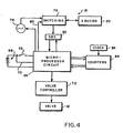
- FIG. 4 A conceptual block diagram of the control circuit 16 is presented in FIG. 4, in which the heart of the circuit is depicted as a microprocessor circuit 66.
- element 66 includes memory and input/output devices of the type usually used with the microprocessor chosen.
- the batteries 68 in the battery pack 18 (FIG. 1) are connected to the microprocessor 66 through the momentary switch 26, which is also shown in FIG. 1.
- a bypass line 70 bypasses the momentary switch 26 and leads to a latch (not shown) internal to circuit 66 that can be operated by the microprocessor.
- This latch is initially open so that power from batteries 68 is not applied to the remaining circuitry by way of bypass line 70. Consequently, the circuitry is not a drain on the batteries 68.
- the internal latch operates to keep power applied to the circuitry even after the momentary switch 26 opens again.
- a subsequent operation of the momentary switch 26 while the internal latch is closed is interpreted as a command to open the latch, and power is removed from the circuit. Otherwise, the latch remains closed, and power continues to be applied to the circuitry, so long as the valve 12 is operated with some frequency. If the valve 12 remains closed for five minutes, though, the latch opens again, removing power from the circuitry so that it is not powered until the pushbutton 26 is again operated.
- the microprocessor circuit 66 controls a valve controller 72 that drives the valve actuator and thus changes the state of the valve 12 in response to commands from the microprocessor 66.
- the microprocessor 66 controls operation of the ultrasonic transducer 20 by operating an oscillator/amplifier 74, which is connected to the transducer 20 through a switching network 76.
- the lines by which the transducer is driven are the same as those by which it returns received pulses, and switching circuitry 76 is controlled by the microprocessor circuit 66, as line 80 suggests, to switch among the several states.
- the switching circuitry 76 connects the oscillator/amplifier to the ultrasonic transducer 20 to drive it and thus transmit ultrasound.
- the switching circuitry 76 disconnects the oscillator/amplifier 74 from the transducer 20 and generally isolates the transducer 20 from the rest of the circuit.
- the circuitry neither transmits nor "listens” for echoes from objects in the transducer's sensing region 22. This avoids reception of spurious echoes and ringing signals that are likely to occur immediately after driving of the transducer 20 stops.
- the switching network 76 connects the transducer 20 to a detection circuit 82 that transmits a signal to the microprocessor 66 when the transducer 20 produces echo signals above predetermined threshold levels.
- a detection circuit 82 that transmits a signal to the microprocessor 66 when the transducer 20 produces echo signals above predetermined threshold levels.
- such circuits typically include time-dependent gain controls to compensate for the high rate of ultrasound attenuation in air.
- the microprocessor When the microprocessor initially causes the transducer 20 to transmit an ultrasound pulse, it resets one of the counters in a counter circuit 84 and enables it so that it begins counting in response to pulses from a free-running clock 86. When the first echo is received, the microprocessor disables the counter so that it stops counting and retains the current count, which is proportional to the distance of the transducer 20 from the object that caused the echo.
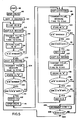
- FIG. 5 is a conceptual flow diagram illustrating the criteria by which the control circuit determines when to open and close the valve.
- the "start" circle 86 represents the point at which the circuit is turned on by operation of the momentary switch 26.
- the circuitry performs initialization routines and opens the valve 12, as block 88 indicates.
- Block 90 represents a fourteen-second wait during which the water flows so that the user can adjust the temperature.
- the valve is then closed, as block 92 indicates, and the circuit goes into the closed-valve routine represented by the rest of the first column of FIG. 5.
- the circuitry measures the time between the transmission and any resultant echo, as was explained above. This function is represented by block 96.
- the resultant measurement is stored in register A, as block 98 indicates, and the circuitry then determines whether the contents of register A are within a range that represents the farthest distance at which the device is designed to respond to the presence of an object. Typically, this distance will be somewhat less than the distance to the bottom of the sink but greater than the distance at which a dish to be rinsed will ordinarily be held.
- Block 106 represents the step of storing the result in a second register, register B, and decision block 108 represents testing the contents of register 9 to determine whether the most recent measured distance is within the predetermined range. If not, the routine returns to the point represented by block 102. Otherwise, the contents of registers A and 9 are compared, as decision block 110 indicates.
- the contents of registers A and B typically represent the measurements from the two most recent ultrasound pulses.
- the contents of registers A and B are both within range, and, if they are equal, then the object has not moved during the intervening half second by more than a distance that is less than the system resolution.
- the test would then be whether the difference between the contents of registers A and B is less than a predetermined number.
- it may be more convenient to tailor the system resolution to the predetermined threshold for movement.
- the test represented by block 110 does not represent the two most recent measurements. For instance, when the result of the test represented by block 110 is negative, the routine repeats the loop represented by blocks 102-110, and it continues in this loop until the contents of register B are in range and different from the contents of register A. Although the two most recent measurements are not compared, the test is acceptable because a positive result of the test represented by block 110 still is an indication that an object is within the target range and movement has occurred.
- an index X is set to a value of three, as block 112 indicates, and the valve is opened.
- the index X is used in providing the delay between a failure to detect motion and the closing of the valve 12
- Block 122 represents testing the resultant value to determine whether or not it is in range.
- the contents of register A are also tested to determine whether they differ from the contents currently stored in register B, as block 124 indicates. If the result of either of these tests is negative, the routine proceeds to the steps represented by block 126, in which the index X is decremented by one, and block 128, in which X is tested to determine whether or not its value is zero. If its value is zero, then the intended delay is complete, and the valve is closed, as block 92 indicates.
- the program then returns to its closed-valve portion. If the test represented by block 128 reveals that X is not yet equal to zero, the routine returns to the step represented by block 116.
- the index X is set equal to three again, as block 130 indicates, and the system waits a half second, makes another measurement, and stores the result in register 9, as blocks 132-136 indicate.
- the contents of register B are tested to determine if they are in range and are then compared with the contents of register A, as blocks 138 and 140 indicate. If the result of either of these tests is negative, the index X is decremented by one, as block 126 indicates, and X is again tested to determine whether or not it is equal to zero, as block 128 indicates
- the index X will have been decremented to zero, and the valve will be closed. If the system fails to detect movement for only a second, the valve will remain open if movement within the range is detected soon thereafter. This time delay associated with the index X eliminates the excessive operation of the valve 12 that might otherwise occur in response to intermittent movements of dishes in the sensing region 22.
- the index X is set equal to three, as block 142 indicates, and the open-valve portion of the routine begins again.
- the flow chart of FIG. 5 does not depict a determination of whether the valve has been inactive for too long a time. However, such a routine runs concurrently with the routine of FIG. 5, which is interrupted to cause the system to shut down if the valve remains closed for more than five minutes.
- the routine employs a second counter in counter circuit 84. This counter is reset whenever the valve 12 closes and begins counting when the valve opens. If the five-minute period mentioned above elapses without a valve opening, this counter reaches a predetermined count that causes the microprocessor to release the internal latch that keeps power applied to the circuit 16. This action turns off the circuit and prevents any further actuation of the valve 12 until the momentary switch 26 is operated again.
- the preferred embodiment of the invention described above employs both distance and movement criteria to determine whether or not to open the valve.
- a stationary object such as a wash basin
- a fork that the user wants to rinse is also a stationary object if the user is not moving it.
- there will normally be enough movement of the object to be rinsed so that the unit will be activated.
- a user will quickly become accustomed to the fact that some movement is required in order to activate the device, and this movement readily becomes a habit that causes no inconvenience.
- it would be quite inconvenient if the device were to be activated by the mere presence of, say, a stationary wash basin or dishes stacked high enough to be within the distance range of the system.
- the preferred embodiment of my device does not employ the frequency-change determination used by Doppler-type devices; instead, it subtracts different measured times.
- vibrations of, for instance, the sink bottom could cause erroneous operation in sensitive Doppler-type devices because high-frequency vibrations might cause considerable Doppler-effect frequency change despite the undetectably small magnitude of the vibrations.
- the movements of dishes are comparatively large in distance, their velocities are not typically great enough for detection by any but the most sensitive Doppler-effect devices, and the most sensitive devices are the ones most subject to erroneous operation.
- detecting motion by measuring distance changes rather than by employing the Doppler effect provides considerable advantages.
Landscapes
- Engineering & Computer Science (AREA)
- General Engineering & Computer Science (AREA)
- Mechanical Engineering (AREA)
- Water Supply & Treatment (AREA)
- Chemical & Material Sciences (AREA)
- Health & Medical Sciences (AREA)
- Life Sciences & Earth Sciences (AREA)
- Hydrology & Water Resources (AREA)
- Public Health (AREA)
- Power Engineering (AREA)
- Combustion & Propulsion (AREA)
- Domestic Plumbing Installations (AREA)
- Electrically Driven Valve-Operating Means (AREA)
- Measurement Of Velocity Or Position Using Acoustic Or Ultrasonic Waves (AREA)
- Paper (AREA)
- Burglar Alarm Systems (AREA)
- Radar Systems Or Details Thereof (AREA)
- Closed-Circuit Television Systems (AREA)
- Flow Control (AREA)
- Cyclones (AREA)
- Fluid-Driven Valves (AREA)
- Massaging Devices (AREA)
- Sink And Installation For Waste Water (AREA)
Applications Claiming Priority (3)
| Application Number | Priority Date | Filing Date | Title |
|---|---|---|---|
| US06/535,213 US4520516A (en) | 1983-09-23 | 1983-09-23 | Ultrasonic flow-control system |
| US535213 | 1983-09-23 | ||
| EP84903589A EP0157830B1 (fr) | 1983-09-23 | 1984-09-19 | Systeme a ultrasons de commande d'un ecoulement |
Related Parent Applications (2)
| Application Number | Title | Priority Date | Filing Date |
|---|---|---|---|
| EP84903589A Division EP0157830B1 (fr) | 1983-09-23 | 1984-09-19 | Systeme a ultrasons de commande d'un ecoulement |
| EP84903589.4 Division | 1985-04-03 |
Related Child Applications (1)
| Application Number | Title | Priority Date | Filing Date |
|---|---|---|---|
| EP96106975.4 Division-Into | 1996-05-03 |
Publications (3)
| Publication Number | Publication Date |
|---|---|
| EP0400688A2 true EP0400688A2 (fr) | 1990-12-05 |
| EP0400688A3 EP0400688A3 (fr) | 1991-10-30 |
| EP0400688B1 EP0400688B1 (fr) | 1997-11-12 |
Family
ID=24133318
Family Applications (2)
| Application Number | Title | Priority Date | Filing Date |
|---|---|---|---|
| EP84903589A Expired - Lifetime EP0157830B1 (fr) | 1983-09-23 | 1984-09-19 | Systeme a ultrasons de commande d'un ecoulement |
| EP90113201A Revoked EP0400688B1 (fr) | 1983-09-23 | 1984-09-19 | Système automatique de commande d'un écoulement |
Family Applications Before (1)
| Application Number | Title | Priority Date | Filing Date |
|---|---|---|---|
| EP84903589A Expired - Lifetime EP0157830B1 (fr) | 1983-09-23 | 1984-09-19 | Systeme a ultrasons de commande d'un ecoulement |
Country Status (9)
| Country | Link |
|---|---|
| US (1) | US4520516A (fr) |
| EP (2) | EP0157830B1 (fr) |
| JP (3) | JPH07113429B2 (fr) |
| AT (1) | ATE160210T1 (fr) |
| AU (1) | AU587169B2 (fr) |
| CA (1) | CA1255779A (fr) |
| DE (2) | DE3484200D1 (fr) |
| IL (1) | IL73025A (fr) |
| WO (1) | WO1985001337A1 (fr) |
Cited By (4)
| Publication number | Priority date | Publication date | Assignee | Title |
|---|---|---|---|---|
| GB2257476A (en) * | 1991-06-26 | 1993-01-13 | Airdri Ltd | Water powered turbine and control system for a valve |
| EP0531646A1 (fr) * | 1991-07-31 | 1993-03-17 | Hansa Metallwerke Ag | Circuit de commande sans contact d'une armature sanitaire et procédé de commande de celui-ci |
| EP0623710A1 (fr) * | 1993-05-07 | 1994-11-09 | SCHROTT, Harald | Robinet sanitaire à commande sans contact |
| WO2005116498A1 (fr) * | 2004-05-27 | 2005-12-08 | Norgren Limited | Dispositif de controle de debit fluidique |
Families Citing this family (94)
| Publication number | Priority date | Publication date | Assignee | Title |
|---|---|---|---|---|
| US4604735A (en) * | 1983-09-23 | 1986-08-05 | Recurrent Solutions, Inc. | Ultrasonic motion detection system |
| JPS61218881A (ja) * | 1985-03-25 | 1986-09-29 | Matsushita Electric Works Ltd | 自動水栓装置 |
| IE58641B1 (en) * | 1985-10-14 | 1993-10-20 | Cws Ag | Device for the automatic cleaning of a toilet seat |
| US4839039B2 (en) * | 1986-02-28 | 1998-12-29 | Recurrent Solutions Ltd | Automatic flow-control device |
| US4982897A (en) * | 1986-08-15 | 1991-01-08 | Iwata Air Compressor Mfg. Co., Ltd. | Spraying method and apparatus employed therefor |
| ATE77457T1 (de) * | 1987-09-22 | 1992-07-15 | Kwc Ag | Elektrisch gesteuerte armatur. |
| JPH01145480A (ja) * | 1987-11-30 | 1989-06-07 | Eisuke Imanaga | 電動開閉蛇口装置 |
| US5025516A (en) * | 1988-03-28 | 1991-06-25 | Sloan Valve Company | Automatic faucet |
| US4894874A (en) * | 1988-03-28 | 1990-01-23 | Sloan Valve Company | Automatic faucet |
| US4998673A (en) * | 1988-04-12 | 1991-03-12 | Sloan Valve Company | Spray head for automatic actuation |
| US4826129A (en) * | 1988-05-03 | 1989-05-02 | Caprilion Enterprise Company | Structure of faucet for automatic water supply and stoppage |
| CA1310682C (fr) * | 1988-09-27 | 1992-11-24 | Kwc Ag | Turbogenerateur mu par canalisation d'eau domestique |
| CA1323906C (fr) * | 1988-09-27 | 1993-11-02 | Ferdinand F. Hochstrasser | Raccord hydraulique pour installations sanitaires domestiques |
| USD321397S (en) | 1988-11-14 | 1991-11-05 | Kohler Co. | Faucet |
| USD325771S (en) | 1989-01-27 | 1992-04-28 | Les Robinets Presto | Electronically controlled faucet |
| DE3905759C1 (fr) * | 1989-02-24 | 1990-03-29 | Cosmos Entwicklungs- Und Forschungsanstalt, Vaduz, Li | |
| US4921211A (en) * | 1989-02-24 | 1990-05-01 | Recurrent Solutions Limited Partnership | Method and apparatus for flow control |
| DE4004099A1 (de) * | 1989-02-24 | 1990-08-30 | Cosmos Entwicklung Forsch | Sanitaerarmatur fuer wasserhaehne |
| US4936508A (en) * | 1989-05-02 | 1990-06-26 | Ingalz Thomas J | Shower head volume meter with alarm signal |
| US4915347A (en) * | 1989-05-18 | 1990-04-10 | Kohler Co. | Solenoid operated faucet |
| NO892348L (no) * | 1989-06-08 | 1990-12-10 | Erland Helmer Larsen | Anordning ved ventil. |
| US5086526A (en) * | 1989-10-10 | 1992-02-11 | International Sanitary Ware Manufacturin Cy, S.A. | Body heat responsive control apparatus |
| US4941219A (en) * | 1989-10-10 | 1990-07-17 | International Sanitary Ware Manufacturing Cy, S.A. | Body heat responsive valve control apparatus |
| JPH0733561Y2 (ja) * | 1989-11-17 | 1995-07-31 | 株式会社イナックス | 蓄電池の充電切れ防止装置 |
| US5243717A (en) * | 1990-03-16 | 1993-09-14 | Inax Corporation | Human body sensing mechanism for an automatic faucet apparatus |
| WO1991017377A1 (fr) * | 1990-05-04 | 1991-11-14 | Masco Corporation Of Indiana | Systeme de robinet automatique ameliore |
| SE465737B (sv) * | 1990-05-31 | 1991-10-21 | Alfa Laval Agri Int | Ventilapparat |
| USD327529S (en) | 1990-09-13 | 1992-06-30 | Kohler Co. | Faucet |
| USD328782S (en) | 1991-01-14 | 1992-08-18 | Speakman Company | Faucet |
| DE4124154C2 (de) * | 1991-07-20 | 1995-11-02 | Oeko Patent Finanz Ag | Sanitärarmatur |
| USD325424S (en) | 1991-07-25 | 1992-04-14 | Kohler Co. | Faucet |
| US5173178A (en) * | 1991-09-24 | 1992-12-22 | Osaki Electric Co., Ltd. | Water purifying apparatus with timed discharge after non-use periods |
| JP2622640B2 (ja) * | 1991-12-30 | 1997-06-18 | 株式会社イナックス | 自動水栓装置 |
| USD329083S (en) | 1992-04-14 | 1992-09-01 | Kohler Co. | Faucet |
| JP3128790B2 (ja) * | 1992-06-15 | 2001-01-29 | 東陶機器株式会社 | 給水制御装置 |
| USD345313S (en) | 1993-02-17 | 1994-03-22 | Guard-Tech Industries, Inc. | Portable motion detector |
| USD351806S (en) | 1993-08-16 | 1994-10-25 | 1uard-Tech Industries, Inc. | Portable motion detector |
| TW286345B (fr) * | 1993-12-20 | 1996-09-21 | Toto Ltd | |
| DE4425294C2 (de) * | 1994-07-18 | 1997-03-06 | Cosmos Entwicklung Forsch | Mit einem Generator vereinigte, flüssigkeitsangetriebene Turbine |
| US6202980B1 (en) | 1999-01-15 | 2001-03-20 | Masco Corporation Of Indiana | Electronic faucet |
| US6885114B2 (en) | 1999-10-05 | 2005-04-26 | Access Business Group International, Llc | Miniature hydro-power generation system |
| US6508272B1 (en) | 2000-11-20 | 2003-01-21 | Arichell Technologies, Inc. | Device and method for operating at least two valves |
| US6427927B1 (en) | 2000-12-08 | 2002-08-06 | Scott Hall | Ultrasonic height control of fountain features |
| DE10132682C1 (de) * | 2001-07-05 | 2002-07-25 | Bosch Gmbh Robert | Heizungsanlage mit Brauch-und /oder Heizungs-Wasserkreislauf und elektrischer Steuerung |
| US6691979B2 (en) | 2001-12-04 | 2004-02-17 | Arichell Technologies, Inc. | Adaptive object-sensing system for automatic flusher |
| CA2469182C (fr) * | 2001-12-04 | 2014-06-03 | Arichell Technologies, Inc. | Robinets electroniques concus pour un fonctionnement a long terme |
| WO2004005628A2 (fr) | 2002-06-24 | 2004-01-15 | Arichell Technologies, Inc. | Systemes de distribution d'eau automatises a commande asservie |
| US7675188B2 (en) * | 2003-10-09 | 2010-03-09 | Access Business Group International, Llc | Miniature hydro-power generation system |
| US7232111B2 (en) * | 2004-01-12 | 2007-06-19 | Masco Corporation Of Indiana | Control arrangement for an automatic residential faucet |
| US7270748B1 (en) * | 2004-09-21 | 2007-09-18 | Next Energy Wave, Inc. | Sterilizing water faucet |
| US20070074767A1 (en) * | 2005-09-30 | 2007-04-05 | Roffey Tony W | Self-charging programmable water valve |
| US8438672B2 (en) | 2005-11-11 | 2013-05-14 | Masco Corporation Of Indiana | Integrated electronic shower system |
| BRPI0621387B1 (pt) | 2006-03-07 | 2018-11-27 | Flowserve Management Company | método para acionar codificador de posição de atuador de válvula e sistema de atuador de válvula |
| US7945973B2 (en) * | 2006-04-06 | 2011-05-24 | Obalit Khorshid | Fluid control system, device and method |
| GB2467661B (en) | 2007-09-20 | 2013-02-13 | Bradley Fixtures Corp | Lavatory system |
| FR2938668A1 (fr) * | 2008-11-19 | 2010-05-21 | Wirecom Technologies | Vanne thermostatique a turbine |
| US8698333B2 (en) * | 2009-09-23 | 2014-04-15 | Zurn Industries, Llc | Flush valve hydrogenerator |
| WO2011044247A1 (fr) | 2009-10-07 | 2011-04-14 | Bradley Fixtures Corporation | Système de lavabo avec sèche-mains |
| US9032565B2 (en) | 2009-12-16 | 2015-05-19 | Kohler Co. | Touchless faucet assembly and method of operation |
| MX2010002024A (es) * | 2010-02-22 | 2011-08-30 | Amc Medicion Y Control S A De C V | Micro generador de energia electrica, acoplado magneticamente. |
| DE102010009215A1 (de) * | 2010-02-25 | 2011-08-25 | Guzman, Cristobal, 74363 | Strömungsregler für Flüssigkeiten mit Energieversorgung über die Strömung |
| US8807521B2 (en) * | 2010-05-25 | 2014-08-19 | Kerry Dunki-Jacobs | Flow control system |
| US9657464B2 (en) * | 2010-05-25 | 2017-05-23 | Kerry Dunki-Jacobs | Flow control system |
| DE102010030653B4 (de) | 2010-06-29 | 2012-01-26 | Hansgrohe Ag | Sanitärarmatur |
| DE102011012152B4 (de) | 2011-02-24 | 2016-09-29 | Sensus Spectrum Llc | Verfahren und Vorrichtung zum Speisen einer Messelektronik |
| DE102011110092A1 (de) | 2011-03-14 | 2012-09-20 | Aquis Sanitär AG | "Sanitärarmatur mit einem Armaturengehäuse und einer elektrischen Kontrolleinheit" |
| US9695579B2 (en) | 2011-03-15 | 2017-07-04 | Sloan Valve Company | Automatic faucets |
| WO2012125213A1 (fr) | 2011-03-15 | 2012-09-20 | Sloan Valve Company | Robinets automatiques |
| US9170148B2 (en) | 2011-04-18 | 2015-10-27 | Bradley Fixtures Corporation | Soap dispenser having fluid level sensor |
| US9267736B2 (en) | 2011-04-18 | 2016-02-23 | Bradley Fixtures Corporation | Hand dryer with point of ingress dependent air delay and filter sensor |
| US20130139889A1 (en) * | 2011-12-05 | 2013-06-06 | Livne Manes Gan | Self powered and automated attachment to a water system |
| CA2873015C (fr) | 2012-03-21 | 2018-11-13 | Bradley Fixtures Corporation | Systeme de bassine et de sechage des mains |
| BR112014031196A2 (pt) | 2012-06-19 | 2017-06-27 | Sensus Spectrum Llc | processo e dispositivo para abastecimento de uma eletrônica de medição com energia elétrica |
| US10100501B2 (en) | 2012-08-24 | 2018-10-16 | Bradley Fixtures Corporation | Multi-purpose hand washing station |
| US9249937B2 (en) | 2012-10-16 | 2016-02-02 | International Business Machines Corporation | Water outlet control system using sound variation |
| AU2014235054B2 (en) | 2013-03-15 | 2017-11-02 | Mueller International, Llc | Systems for measuring properties of water in a water distribution system |
| JP2015052282A (ja) * | 2013-09-06 | 2015-03-19 | 株式会社 テクニカルサポート | 小型水力発電機 |
| DE102016108045A1 (de) | 2016-04-29 | 2017-11-02 | A. u. K. Müller GmbH & Co. KG | Armaturauslass und Armatur |
| US11015329B2 (en) | 2016-06-08 | 2021-05-25 | Bradley Corporation | Lavatory drain system |
| US10041236B2 (en) | 2016-06-08 | 2018-08-07 | Bradley Corporation | Multi-function fixture for a lavatory system |
| CN106122556A (zh) * | 2016-08-24 | 2016-11-16 | 宁波中车时代电气设备有限公司 | 一种洗手器的动态感应方法及洗手器 |
| KR20180066449A (ko) * | 2016-12-09 | 2018-06-19 | 신종현 | 샤워기 |
| DE202017103194U1 (de) | 2017-05-26 | 2018-08-28 | Neoperl Gmbh | Sanitärventil |
| WO2019104354A1 (fr) * | 2017-11-27 | 2019-05-31 | Sink Tech, LLC | Système et procédé de nettoyage et de surveillance d'eau d'hôtellerie |
| US11255076B2 (en) | 2018-10-19 | 2022-02-22 | Abstract Engineering, Inc. | System and method for controlling and monitoring bathroom water flow |
| US11045828B2 (en) | 2018-10-19 | 2021-06-29 | Abstract Engineering, Inc. | System and method for controlling and monitoring bathroom water flow |
| EP4077820B1 (fr) * | 2019-12-19 | 2024-08-14 | Emerson Electric Co. | Appareil de robinet configurable et procédés de mise en uvre et d'utilisation dudit appareil de robinet configurable |
| FR3108414B1 (fr) * | 2020-03-18 | 2022-06-10 | Vernet | Dispositif instrumenté pour un robinet mitigeur, ainsi que robinet mitigeur comprenant un tel dispositif instrumenté |
| US11984768B2 (en) | 2020-04-17 | 2024-05-14 | Zurn Water, Llc | Hydroelectric generator for faucet and flush valve |
| US11725366B2 (en) | 2020-07-16 | 2023-08-15 | Mueller International, Llc | Remote-operated flushing system |
| US12493355B2 (en) | 2022-04-14 | 2025-12-09 | Kohler Co. | Touchless plumbing control system |
| CN114738167B (zh) * | 2022-04-29 | 2023-06-16 | 河海大学 | 一种带有“x”型翼型转轮可用于管道水流发电的微型水轮机 |
| US12152377B1 (en) * | 2023-08-01 | 2024-11-26 | The Hoffman Group | Faucet hand sterilizer |
| US12529213B1 (en) * | 2024-09-25 | 2026-01-20 | Jui-Chien Chen | Water faucet with water flow monitoring |
Family Cites Families (28)
| Publication number | Priority date | Publication date | Assignee | Title |
|---|---|---|---|---|
| US2438207A (en) * | 1944-03-16 | 1948-03-23 | Milton Wilson C | Means for controlling the flushing of urinals |
| US2507966A (en) * | 1946-08-29 | 1950-05-16 | Sloan Valve Co | Automatic flushing system |
| US2603794A (en) * | 1949-01-21 | 1952-07-22 | Bokser Lewis | Electric eye for automatically operating flushing valves |
| US3151340A (en) * | 1961-10-26 | 1964-10-06 | Carousel Sanwa Licensing Corp | Automatic water-supply apparatus |
| US3314081A (en) * | 1964-05-22 | 1967-04-18 | Tung Sol Electric Inc | Capacity operated automatic flushing system |
| GB1058000A (en) * | 1964-10-29 | 1967-02-08 | Omron Tateisi Electronics Co | An automatic water supply control system |
| GB1212780A (en) * | 1967-11-27 | 1970-11-18 | Omron Tateisi Electronics Co | An automatic water supply system |
| JPS4938293Y1 (fr) * | 1969-02-14 | 1974-10-21 | ||
| US3638680A (en) * | 1970-02-25 | 1972-02-01 | Hans W Kopp | Table with liquid outlet |
| US3670167A (en) * | 1970-05-14 | 1972-06-13 | American Standard Inc | Proximity switching equipment |
| DE2034877C2 (de) * | 1970-07-07 | 1971-12-30 | Visolux Elektronik Richard Sie | Auf bewegung im wasserauslaufbereich ansprechende steuereinrichtung für wasserzuführungen von waschbecken od dgl |
| US3776279A (en) * | 1971-02-05 | 1973-12-04 | Kieley & Mueller | System for changing fluid movement into electrical energy |
| US3814376A (en) * | 1972-08-09 | 1974-06-04 | Parker Hannifin Corp | Solenoid operated valve with magnetic latch |
| JPS49111222A (fr) * | 1973-02-24 | 1974-10-23 | ||
| JPS5068824U (fr) * | 1973-10-25 | 1975-06-19 | ||
| US4141091A (en) * | 1976-12-10 | 1979-02-27 | Pulvari Charles F | Automated flush system |
| GB1570898A (en) * | 1976-12-22 | 1980-07-09 | Standard Telephones Cables Ltd | Ultrasonic faucet control |
| JPS53103935U (fr) * | 1977-01-27 | 1978-08-22 | ||
| DE2721254C3 (de) * | 1977-05-11 | 1980-01-03 | Siemens Ag, 1000 Berlin Und 8000 Muenchen | Schaltungsanordnung für einen Bewegungsdetektor |
| DE2721217C3 (de) * | 1977-05-11 | 1980-06-12 | Siemens Ag, 1000 Berlin Und 8000 Muenchen | Auslauf armatur mit beruhrungsloser Steuerung des Absperrmechanismus |
| US4229811A (en) * | 1978-11-09 | 1980-10-21 | General Electric Company | Intrusion detection method and apparatus |
| DE2938969C2 (de) * | 1979-09-26 | 1984-12-13 | Siemens AG, 1000 Berlin und 8000 München | Ultraschall-Raumüberwachungssystem nach dem Impuls-Echo-Verfahren |
| US4309781A (en) * | 1980-05-09 | 1982-01-12 | Sloan Valve Company | Automatic flushing system |
| JPS5717024A (en) * | 1980-07-04 | 1982-01-28 | Hitachi Ltd | Discharge flow rate automatic control method for motive power recovering device |
| DE3071890D1 (en) * | 1980-08-20 | 1987-02-19 | Secom Co Ltd | Ultrasonic warning system |
| US4402095A (en) * | 1981-03-26 | 1983-09-06 | Pepper Robert B | Ultrasonically operated water faucet |
| FR2508210A1 (fr) * | 1981-06-22 | 1982-12-24 | Alsthom Cgee | Detecteur d'intrusion a ultrasons |
| JPS58114956U (ja) * | 1982-01-29 | 1983-08-05 | 株式会社 京浜精機製作所 | 電動弁の弁装置 |
-
1983
- 1983-09-23 US US06/535,213 patent/US4520516A/en not_active Expired - Lifetime
-
1984
- 1984-09-19 AT AT90113201T patent/ATE160210T1/de active
- 1984-09-19 JP JP59503549A patent/JPH07113429B2/ja not_active Expired - Fee Related
- 1984-09-19 WO PCT/US1984/001481 patent/WO1985001337A1/fr not_active Ceased
- 1984-09-19 DE DE8484903589T patent/DE3484200D1/de not_active Expired - Fee Related
- 1984-09-19 EP EP84903589A patent/EP0157830B1/fr not_active Expired - Lifetime
- 1984-09-19 DE DE3486460T patent/DE3486460T2/de not_active Revoked
- 1984-09-19 EP EP90113201A patent/EP0400688B1/fr not_active Revoked
- 1984-09-21 IL IL73025A patent/IL73025A/xx not_active IP Right Cessation
- 1984-11-30 AU AU36056/84A patent/AU587169B2/en not_active Ceased
-
1985
- 1985-03-07 CA CA000475896A patent/CA1255779A/fr not_active Expired
-
1991
- 1991-01-31 JP JP3098357A patent/JP2620579B2/ja not_active Expired - Fee Related
- 1991-08-14 JP JP3204241A patent/JPH0811983B2/ja not_active Expired - Fee Related
Cited By (7)
| Publication number | Priority date | Publication date | Assignee | Title |
|---|---|---|---|---|
| GB2257476A (en) * | 1991-06-26 | 1993-01-13 | Airdri Ltd | Water powered turbine and control system for a valve |
| GB2257476B (en) * | 1991-06-26 | 1995-09-27 | Airdri Ltd | Water powered control system |
| EP0531646A1 (fr) * | 1991-07-31 | 1993-03-17 | Hansa Metallwerke Ag | Circuit de commande sans contact d'une armature sanitaire et procédé de commande de celui-ci |
| EP0623710A1 (fr) * | 1993-05-07 | 1994-11-09 | SCHROTT, Harald | Robinet sanitaire à commande sans contact |
| WO2005116498A1 (fr) * | 2004-05-27 | 2005-12-08 | Norgren Limited | Dispositif de controle de debit fluidique |
| CN100540963C (zh) * | 2004-05-27 | 2009-09-16 | 诺格伦有限公司 | 流体流控制设备 |
| US7775504B2 (en) | 2004-05-27 | 2010-08-17 | Norgren Limited | Fluid flow control device |
Also Published As
| Publication number | Publication date |
|---|---|
| AU3605684A (en) | 1986-06-05 |
| DE3486460T2 (de) | 1998-04-23 |
| JPH07113429B2 (ja) | 1995-12-06 |
| WO1985001337A1 (fr) | 1985-03-28 |
| IL73025A0 (en) | 1984-12-31 |
| EP0400688A3 (fr) | 1991-10-30 |
| IL73025A (en) | 1990-02-09 |
| AU587169B2 (en) | 1989-08-10 |
| EP0157830B1 (fr) | 1991-02-27 |
| DE3484200D1 (de) | 1991-04-04 |
| EP0400688B1 (fr) | 1997-11-12 |
| JPH06207682A (ja) | 1994-07-26 |
| JPH0811983B2 (ja) | 1996-02-07 |
| EP0157830A1 (fr) | 1985-10-16 |
| ATE160210T1 (de) | 1997-11-15 |
| JP2620579B2 (ja) | 1997-06-18 |
| DE3486460D1 (de) | 1997-12-18 |
| JPS61500232A (ja) | 1986-02-06 |
| JPH0727243A (ja) | 1995-01-27 |
| EP0157830A4 (fr) | 1987-01-22 |
| CA1255779A (fr) | 1989-06-13 |
| US4520516A (en) | 1985-06-04 |
Similar Documents
| Publication | Publication Date | Title |
|---|---|---|
| US4604735A (en) | Ultrasonic motion detection system | |
| US4520516A (en) | Ultrasonic flow-control system | |
| US4869287A (en) | Ultrasonically operated water faucet | |
| US4402095A (en) | Ultrasonically operated water faucet | |
| AU643985B2 (en) | Automatic flow-control device | |
| US4921211A (en) | Method and apparatus for flow control | |
| US6388609B2 (en) | Radar devices for low power applications and bathroom fixtures | |
| CN106527165B (zh) | 人体监测装置、智能坐便器及智能家用电器 | |
| WO2006042053A2 (fr) | Module intelligent de regulation d'ecoulement et systeme de gestion de l'eau | |
| WO2011000275A1 (fr) | Système et procédé d'induction automatique | |
| US4788998A (en) | Ultrasonically operated water faucet | |
| JP2016506511A (ja) | トイレのタッチレスアクティブ化 | |
| JP4006547B2 (ja) | 物体検知装置 | |
| CA1278075C (fr) | Systeme ultrasonique regulateur de debit | |
| CN219994544U (zh) | 一种脸盆水龙头 | |
| US12227928B2 (en) | Sensor faucet | |
| CN223994741U (zh) | 智能感应无接触饮水机 | |
| JPH03168482A (ja) | 自動水栓 | |
| JP7811354B2 (ja) | 電動排水栓装置 | |
| CN222275676U (zh) | 一种智能卫浴设备 | |
| WO1999014647A1 (fr) | Ameliorations relatives aux systemes automatises d'ecoulement fluidique | |
| AU607696C (en) | Automatic flow-control device | |
| CN116658671A (zh) | 一种脸盆水龙头及其使用方法 | |
| JPH0433334B2 (fr) | ||
| JPH0729077U (ja) | 衛生器具の自動洗浄装置 |
Legal Events
| Date | Code | Title | Description |
|---|---|---|---|
| PUAI | Public reference made under article 153(3) epc to a published international application that has entered the european phase |
Free format text: ORIGINAL CODE: 0009012 |
|
| AC | Divisional application: reference to earlier application |
Ref document number: 157830 Country of ref document: EP |
|
| AK | Designated contracting states |
Kind code of ref document: A2 Designated state(s): AT BE CH DE FR GB LI LU NL SE |
|
| RAP1 | Party data changed (applicant data changed or rights of an application transferred) |
Owner name: RECURRENT SOLUTIONS, INC. |
|
| RIN1 | Information on inventor provided before grant (corrected) |
Inventor name: PARSONS, NATAN E. |
|
| PUAL | Search report despatched |
Free format text: ORIGINAL CODE: 0009013 |
|
| AK | Designated contracting states |
Kind code of ref document: A3 Designated state(s): AT BE CH DE FR GB LI LU NL SE |
|
| 17P | Request for examination filed |
Effective date: 19920427 |
|
| 17Q | First examination report despatched |
Effective date: 19920814 |
|
| APAB | Appeal dossier modified |
Free format text: ORIGINAL CODE: EPIDOS NOAPE |
|
| GRAG | Despatch of communication of intention to grant |
Free format text: ORIGINAL CODE: EPIDOS AGRA |
|
| GRAH | Despatch of communication of intention to grant a patent |
Free format text: ORIGINAL CODE: EPIDOS IGRA |
|
| GRAH | Despatch of communication of intention to grant a patent |
Free format text: ORIGINAL CODE: EPIDOS IGRA |
|
| RAP1 | Party data changed (applicant data changed or rights of an application transferred) |
Owner name: ARICHELL TECHNOLOGIES, INC. |
|
| GRAA | (expected) grant |
Free format text: ORIGINAL CODE: 0009210 |
|
| AC | Divisional application: reference to earlier application |
Ref document number: 157830 Country of ref document: EP |
|
| AK | Designated contracting states |
Kind code of ref document: B1 Designated state(s): AT BE CH DE FR GB LI LU NL SE |
|
| DX | Miscellaneous (deleted) | ||
| REF | Corresponds to: |
Ref document number: 160210 Country of ref document: AT Date of ref document: 19971115 Kind code of ref document: T |
|
| REG | Reference to a national code |
Ref country code: CH Ref legal event code: EP |
|
| REF | Corresponds to: |
Ref document number: 3486460 Country of ref document: DE Date of ref document: 19971218 |
|
| REG | Reference to a national code |
Ref country code: CH Ref legal event code: NV Representative=s name: RITSCHER & SEIFERT PATENTANWAELTE VSP |
|
| ET | Fr: translation filed | ||
| PLAV | Examination of admissibility of opposition |
Free format text: ORIGINAL CODE: EPIDOS OPEX |
|
| PLBI | Opposition filed |
Free format text: ORIGINAL CODE: 0009260 |
|
| PLBQ | Unpublished change to opponent data |
Free format text: ORIGINAL CODE: EPIDOS OPPO |
|
| PLBI | Opposition filed |
Free format text: ORIGINAL CODE: 0009260 |
|
| PLBQ | Unpublished change to opponent data |
Free format text: ORIGINAL CODE: EPIDOS OPPO |
|
| PLBI | Opposition filed |
Free format text: ORIGINAL CODE: 0009260 |
|
| PLBQ | Unpublished change to opponent data |
Free format text: ORIGINAL CODE: EPIDOS OPPO |
|
| PLBI | Opposition filed |
Free format text: ORIGINAL CODE: 0009260 |
|
| 26 | Opposition filed |
Opponent name: FRIEDRICH GROHE AKTIENGESELLSCHAFT Effective date: 19980721 |
|
| PLAV | Examination of admissibility of opposition |
Free format text: ORIGINAL CODE: EPIDOS OPEX |
|
| PLBF | Reply of patent proprietor to notice(s) of opposition |
Free format text: ORIGINAL CODE: EPIDOS OBSO |
|
| 26 | Opposition filed |
Opponent name: INTERNATIONAL SANITARY WARE MANUFACTURING CY, INT Effective date: 19980804 Opponent name: KERAMAG KERAMISCHE WERKE AG Effective date: 19980731 Opponent name: FRIEDRICH GROHE AKTIENGESELLSCHAFT Effective date: 19980721 |
|
| 26 | Opposition filed |
Opponent name: HANS GROHE GMBH & CO. KG Effective date: 19980811 Opponent name: GEBERIT TECHNIK AG Effective date: 19980810 Opponent name: INTERNATIONAL SANITARY WARE MANUFACTURING CY, INT Effective date: 19980804 Opponent name: KERAMAG KERAMISCHE WERKE AG Effective date: 19980731 Opponent name: FRIEDRICH GROHE AKTIENGESELLSCHAFT Effective date: 19980721 |
|
| 26 | Opposition filed |
Opponent name: HANS GROHE GMBH & CO. KG Effective date: 19980811 Opponent name: MEPA DIPL-ING. ROBERT KUEHNEL GMBH Effective date: 19980806 Opponent name: GEBERIT TECHNIK AG Effective date: 19980810 Opponent name: INTERNATIONAL SANITARY WARE MANUFACTURING CY, INT Effective date: 19980804 Opponent name: KERAMAG KERAMISCHE WERKE AG Effective date: 19980731 Opponent name: FRIEDRICH GROHE AKTIENGESELLSCHAFT Effective date: 19980721 |
|
| NLR1 | Nl: opposition has been filed with the epo |
Opponent name: FRIEDRICH GROHE AKTIENGESELLSCHAFT |
|
| NLR1 | Nl: opposition has been filed with the epo |
Opponent name: HANS GROHE GMBH & CO. KG Opponent name: GEBERIT TECHNIK AG Opponent name: INTERNATIONAL SANITARY WARE MANUFACTURING CY, INTE Opponent name: KERAMAG KERAMISCHE WERKE AG Opponent name: FRIEDRICH GROHE AKTIENGESELLSCHAFT |
|
| PLAV | Examination of admissibility of opposition |
Free format text: ORIGINAL CODE: EPIDOS OPEX |
|
| PLBF | Reply of patent proprietor to notice(s) of opposition |
Free format text: ORIGINAL CODE: EPIDOS OBSO |
|
| PLBF | Reply of patent proprietor to notice(s) of opposition |
Free format text: ORIGINAL CODE: EPIDOS OBSO |
|
| PLAB | Opposition data, opponent's data or that of the opponent's representative modified |
Free format text: ORIGINAL CODE: 0009299OPPO |
|
| R26 | Opposition filed (corrected) |
Opponent name: FRIEDRICH GROHE AKTIENGESELLSCHAFT * 19980731 KERA Effective date: 19980721 |
|
| NLR1 | Nl: opposition has been filed with the epo |
Opponent name: HANS GROHE AG Opponent name: MEPA DIPL-ING. ROBERT KUEHNEL GMBH Opponent name: GEBERIT TECHNIK AG Opponent name: INTERNATIONAL SANITARY WARE MANUFACTURING CY, INTE Opponent name: KERAMAG KERAMISCHE WERKE AG Opponent name: FRIEDRICH GROHE AKTIENGESELLSCHAFT |
|
| PGFP | Annual fee paid to national office [announced via postgrant information from national office to epo] |
Ref country code: SE Payment date: 20010920 Year of fee payment: 18 Ref country code: FR Payment date: 20010920 Year of fee payment: 18 Ref country code: DE Payment date: 20010920 Year of fee payment: 18 |
|
| PGFP | Annual fee paid to national office [announced via postgrant information from national office to epo] |
Ref country code: GB Payment date: 20010921 Year of fee payment: 18 Ref country code: AT Payment date: 20010921 Year of fee payment: 18 |
|
| PGFP | Annual fee paid to national office [announced via postgrant information from national office to epo] |
Ref country code: CH Payment date: 20010924 Year of fee payment: 18 |
|
| PGFP | Annual fee paid to national office [announced via postgrant information from national office to epo] |
Ref country code: NL Payment date: 20010925 Year of fee payment: 18 |
|
| PGFP | Annual fee paid to national office [announced via postgrant information from national office to epo] |
Ref country code: LU Payment date: 20011004 Year of fee payment: 18 |
|
| PGFP | Annual fee paid to national office [announced via postgrant information from national office to epo] |
Ref country code: BE Payment date: 20011010 Year of fee payment: 18 |
|
| REG | Reference to a national code |
Ref country code: GB Ref legal event code: IF02 |
|
| PLAB | Opposition data, opponent's data or that of the opponent's representative modified |
Free format text: ORIGINAL CODE: 0009299OPPO |
|
| PLBP | Opposition withdrawn |
Free format text: ORIGINAL CODE: 0009264 |
|
| 26 | Opposition filed |
Opponent name: HANSGROHE AG Effective date: 19980811 Opponent name: MEPA DIPL-ING. ROBERT KUEHNEL GMBH Effective date: 19980806 Opponent name: GEBERIT TECHNIK AG Effective date: 19980810 Opponent name: INTERNATIONAL SANITARY WARE MANUFACTURING CY, INTE Effective date: 19980804 Opponent name: FRIEDRICH GROHE AG & CO. KG Effective date: 19980721 |
|
| R26 | Opposition filed (corrected) |
Opponent name: FRIEDRICH GROHE AG & CO. KG * 19980804 INTERNATION Effective date: 19980721 |
|
| NLR1 | Nl: opposition has been filed with the epo |
Opponent name: HANSGROHE AG Opponent name: MEPA DIPL-ING. ROBERT KUEHNEL GMBH Opponent name: GEBERIT TECHNIK AG Opponent name: INTERNATIONAL SANITARY WARE MANUFACTURING CY, INTE Opponent name: FRIEDRICH GROHE AG & CO. KG |
|
| PG25 | Lapsed in a contracting state [announced via postgrant information from national office to epo] |
Ref country code: SE Free format text: LAPSE BECAUSE OF NON-PAYMENT OF DUE FEES Effective date: 20020920 |
|
| RDAH | Patent revoked |
Free format text: ORIGINAL CODE: EPIDOS REVO |
|
| RTI2 | Title (correction) |
Free format text: AUTOMATIC FLOW-CONTROL SYSTEM |
|
| RTI2 | Title (correction) |
Free format text: AUTOMATIC FLOW-CONTROL SYSTEM |
|
| RDAG | Patent revoked |
Free format text: ORIGINAL CODE: 0009271 |
|
| STAA | Information on the status of an ep patent application or granted ep patent |
Free format text: STATUS: PATENT REVOKED |
|
| REG | Reference to a national code |
Ref country code: CH Ref legal event code: PL |
|
| EUG | Se: european patent has lapsed | ||
| 27W | Patent revoked |
Effective date: 20021212 |
|
| GBC | Gb: translation of claims filed (gb section 78(7)/1977) |
Free format text: 20021212 |
|
| APAH | Appeal reference modified |
Free format text: ORIGINAL CODE: EPIDOSCREFNO |
|
| PLAB | Opposition data, opponent's data or that of the opponent's representative modified |
Free format text: ORIGINAL CODE: 0009299OPPO |