EP0400755B1 - Digitales Übertragungssystem unter Verwendung der Teilbandkodierung eines digitalen Signals - Google Patents
Digitales Übertragungssystem unter Verwendung der Teilbandkodierung eines digitalen Signals Download PDFInfo
- Publication number
- EP0400755B1 EP0400755B1 EP90201369A EP90201369A EP0400755B1 EP 0400755 B1 EP0400755 B1 EP 0400755B1 EP 90201369 A EP90201369 A EP 90201369A EP 90201369 A EP90201369 A EP 90201369A EP 0400755 B1 EP0400755 B1 EP 0400755B1
- Authority
- EP
- European Patent Office
- Prior art keywords
- coupled
- signal
- output
- inputs
- filter
- Prior art date
- Legal status (The legal status is an assumption and is not a legal conclusion. Google has not performed a legal analysis and makes no representation as to the accuracy of the status listed.)
- Expired - Lifetime
Links
Images




Classifications
-
- H—ELECTRICITY
- H04—ELECTRIC COMMUNICATION TECHNIQUE
- H04L—TRANSMISSION OF DIGITAL INFORMATION, e.g. TELEGRAPHIC COMMUNICATION
- H04L12/00—Data switching networks
- H04L12/28—Data switching networks characterised by path configuration, e.g. LAN [Local Area Networks] or WAN [Wide Area Networks]
-
- H—ELECTRICITY
- H04—ELECTRIC COMMUNICATION TECHNIQUE
- H04B—TRANSMISSION
- H04B1/00—Details of transmission systems, not covered by a single one of groups H04B3/00 - H04B13/00; Details of transmission systems not characterised by the medium used for transmission
- H04B1/66—Details of transmission systems, not covered by a single one of groups H04B3/00 - H04B13/00; Details of transmission systems not characterised by the medium used for transmission for reducing bandwidth of signals; for improving efficiency of transmission
- H04B1/667—Details of transmission systems, not covered by a single one of groups H04B3/00 - H04B13/00; Details of transmission systems not characterised by the medium used for transmission for reducing bandwidth of signals; for improving efficiency of transmission using a division in frequency subbands
-
- G—PHYSICS
- G06—COMPUTING OR CALCULATING; COUNTING
- G06T—IMAGE DATA PROCESSING OR GENERATION, IN GENERAL
- G06T9/00—Image coding
- G06T9/007—Transform coding, e.g. discrete cosine transform
-
- H—ELECTRICITY
- H03—ELECTRONIC CIRCUITRY
- H03H—IMPEDANCE NETWORKS, e.g. RESONANT CIRCUITS; RESONATORS
- H03H17/00—Networks using digital techniques
- H03H17/02—Frequency selective networks
- H03H17/0248—Filters characterised by a particular frequency response or filtering method
- H03H17/0264—Filter sets with mutual related characteristics
- H03H17/0266—Filter banks
Definitions
- the invention relates to a digital transmission system having a transmitter and a receiver, the transmitter including a coder and the receiver including a decoder, for subband coding of a digital signal, such as a digital audio signal, having a given sampling rate F S , the coder being responsive to the digital signal, for generating a number of M sub-band signals with sampling rate reduction, the coder dividing the digital signal band into successive subbands of band numbers m(1 ⁇ m ⁇ M) increasing with frequency, the decoder being responsive to the M subband signals for constructing a replica of the digital signal, this decoder merging the subbands to the digital signal band, with sampling rate increase.
- the invention also relates to a transmitter and a receiver for use in the transmission system, a coder for use in the transmitter, a decoder for use in the receiver, an analysis filter for use in the coder, a synthesis filter for use in the decoder, and a digital audio signal recording or reproducing apparatus comprising the transmitter and the receiver respectively.
- a system for subband coding is known from the article entitled "The critical Band Coder - Digital encoding of speech signals based on the perceptual requirements of the auditory system" by M.E. Krasner, Proc. IEEE ICASSP80, Vol. 1, pp. 327-311, April 9-11, 1980.
- this known system use is made of a subdivision of the speech signal band into a number of subbands, whose bandwidths approximately correspond with the bandwidth of the critical bands of the human auditory system in the respective frequency ranges (compare fig. 2 in the article by Krasner).
- This subdivision has been chosen because on the basis of psycho acoustic experiments it may be expected that in a such like subband the quantization noise will be optimally masked by the signals within this subband when the quantizing takes account of the noise masking curve of the human auditory system (this curve indicates the threshold for masking the noise in a critical band by a single tone in the centre of the critical band, compare fig. 3 in Krasner's article.
- the invention has for its object to provide a digital transmission system in which the information transmitted via the transmission medium between the transmitter and the receiver is divided in subbands having all approximately the same bandwidth, and which is constructed such that practically not distortion because of aliasing occurs in the reconstructed signal at the receiver side, and where the coder and decoder are very efficient with respect to computation time and complexity of the circuitry needed.
- the digital transmission system in accordance with the with the invention is characterized in that the coder comprises analysis filter means and a signal processing unit, the analysis filter means comprises M analysis filters each having one input and two outputs, the 2 M outputs on the filters being coupled to 2 M outputs of the analysis filter means for supplying 2 M output signals with a sampling rate F S /M, each analysis filter being adapted to apply two different filterings on the signal applied to its input and to supply each of the two different filtered versions of that input signal to a corresponding one of the two outputs, each one of the 2M filter outputs being coupled to a corresponding one of 2M inputs of a signal processing unit, the processing unit having M outputs coupled to M outputs of the coder for supplying the M subband signals, the signal processing unit being adapted to supply output signals on each of M outputs, an output signal being a combination of at least a number of input signals applied to its 2M inputs, the decoder comprises another signal processing unit and synthesis filter means, the other signal processing unit having M inputs for
- the measures according to the invention are based on the recognition that computation can be greatly simplified by arranging a sample rate decreaser in the form of the first unit before the analysis filters in the transmitter and by arranging a sample rate increaser in the form of the second unit behind the synthesis filters in the receiver, in that the computations are now applied on signals with a lower sampling rate.
- the transmitter in the known system however does not generate subbands of substantially equal bandwidths, in that the lowest subband in the known system has a bandwidth of half the bandwidth of the other bandwidths.
- the filters and the processing unit in the known system differ from the filters and the processing unit in the system according to the invention in that the filters apply two different filterings on the signals applied to their apply two different filterings on the signals applied to their inputs instead of one, such as in the known system. This makes the content of the information transfer between the filters and the processing unit according to the invention twice of that in the known system.
- EP 190.796 Al discloses a coder comprising analysis filter means and a signal processing unit and a decoder comprising an other signal processing unit and synthesis filter means.
- the known coder and decoder differ from the coder and decoder claimed in that no information is given as to how to obtain the multiplication values for the analysis or synthesis filters in the case that M is even, and the number of coefficients in the standard filter is odd.
- each analysis filter comprises a series arrangement of delay sections having equal delay (T), the input of the filter being coupled to the input of the first delay section, outputs of at least a number of odd numbered delay sections in the series arrangement being coupled to corresponding inputs of a first signal combination unit, outputs of least a number of even numbered delay sections in the series arrangement being coupled to corresponding inputs of a second signal combination unit, outputs of the first and second signal combination unit being coupled to the first and second output respectively of the filter.
- T delay
- the outputs of odd numbered delay sections being coupled to inputs of the first signal combination unit only, and outputs of even numbered delay sections are coupled to inputs of the second signal combination unit only.
- each analysis filter comprises two series arrangements of delay sections having equal delay (2T), the input of the filter being coupled to the inputs of the first and at least a number of other delay sections in each series arrangement, the outputs of the two series arrangements being coupled to the first and second output of the filter respectively, a further delay section having a delay (T) that equals half the delay of the delay sections in the series arrangements, being coupled in the signal path from the input to the second output of the filter, the said further delay section not being included in the signal path from the inputto the first output of the filter.
- each synthesis filter comprises two series arrangements of delay sections, having equal delay (2T), the first and second inputs of the filter being coupled to an input of the first delay section of the first and second series arrangement respectively, outputs of at least a number of delay sections in the first series arrangement being coupled to corresponding inputs of a signal combination unit, outputs of at least a number of delay sections in the second series arrangement also being coupled to corresponding inputs of the signal combination unit, an output of the signal combination unit being coupled to the filter output, a further delay section having a delay (T) that equals half the delay of the delay sections in the series arrangements, being coupled in the signal path from the second input to the output of the filter, the said further delay section not being included in the signal path from the first input to the output of the filter.
- 2T delay
- each synthesis filter comprises a series arrangement of delay sections having equal delay (T), the first input of the filter being coupled to inputs of at least a number of odd numbered delay sections in the series arrangement, the second input of the filter being coupled to inputs of at least a number of even numbered delay sections in the series arrangement, the output of the last delay section being coupled to the output of the filter.
- T delay
- the first filter input is coupled to inputs of odd numbered delay sections only
- the second filter input is coupled to inputs of even numbered delay sections only.
- the signal processing unit comprises M signal combination units, each having an output coupled to a corresponding one of the M outputs of the signal processing unit, in that for each signal combination unit, at least a number of inputs of the 2M inputs of the processing unit are coupled to corresponding inputs of the said signal combination unit, via corresponding multiplication units.
- the corresponding other signal processing unit on the receiver side then comprises 2M signal combination units, each having an output coupled to a corresponding one of the 2M outputs of the processing unit, in that, for each signal combination unit, at least a number of inputs of the M inputs of the processing units are coupled to corresponding inputs of the said signal combination unit, via corresponding multiplication units.
- each analysis filter On the transmitter side the system may be further characterized in that the two outputs of each analysis filter are each coupled to their corresponding inputs of the signal processing unit via a corresponding signal amplification unit, both amplification units being adapted to amplify the signals applied to their inputs by the same complex value, the complex values preferably being different for amplification units coupled to different analysis filters.
- each output of the processing unit may be coupled to its corresponding output of the coder via a series arrangement of a signal amplification unit and real value determinator, the signal amplification unit being adapted to amplify the signal applied to its input by a complex value.
- the system may be further characterized in that the two outputs of each pair of outputs of the other signal processing unit are each coupled to their corresponding input of a synthesis filter via a corresponding signal amplification unit, both amplification units being adapted to amplify the signals applied to their inputs by the same complex value, the complex values preferably being different for amplification units coupled to different synthesis filters.
- the M inputs of the decoder may be coupled to their corresponding one of the M inputs of the other processing unit via a signal amplification unit, the signal amplification unit being adapted to amplify the signal applied to its input by another complex value.
- Figure 1 discloses a block diagram of the digital transmission system.
- the system has an input terminal 1 coupled to an input 2 of a first unit 3, for receiving a digital system IN having a given sampling rate F S .
- the first unit has M outputs 4.1 to 4.M on which ouput signals U1 to U M are available.
- the first unit 3 is adapted to realize a sample rate decrease by a factor M on the input signal IN applied to its input 2.
- M analysis filters 6.1 to 6.M are present, each analysis filter m having an input 5.m coupled to a corresponding one (4.m) of the M outputs of the first unit 3. m runs from 1 to M.
- Each analysis filter 6.m has two outputs 7.ma and 7.mb.
- Each analysis filter (6.m) is adapted to apply two different filterings on the signal (U m ) applied to its input (5.m) and to supply each of the two different filtered versions of that input signal (U m ) to a corresponding on of the two outputs (7.ma and 7.mb).
- the construction and the functioning of the analysis filters will be explained later with reference to the figures 3, 4 and 10.
- Each one of the 2M filter outputs 7.1a, 7.1b, 7.2a, 7.2b, ..., 7.ma, 7.mb, ..., 7Ma, 7Mb are coupled to a corresponding one of 2M inputs 8.1, 8.2, ..., 8M, 8M+1, ..., 8.2M of a signal processing unit 9.
- the processing unit 9 has M outputs to 10.1 to 10.M.
- the processing unit 9 is adapted to supply different output signals on each of its M outputs, an output signal being a combination of at least a number of input signals applied to its 2M inputs.
- the signal processing unit 9 supplies the M subband signals S1 to S M , each subband signal S m being available on a corresponding one (10.m) of the M outputs of the processing unit 9.
- the input signal IN applied to the input 1 and having a sampling rate of F S occupies a bandwidth equal to F S /2. Division of the signal bandwidth by a factor of M this means that the bandwidth of the subbands B1 to B M all equal F S /2M, see figure 10c, s1 in figure 1 being a down sampled version of the signal present in subband B1, s2 being a down sampled version of the signal present in subband B2, etc.
- the M subband signals can, if necessary, further be processed, e.g. in an additional quantizer (not shown), in which an (adaptive) quantization can be applied on the signals in order to realise a significant reduction in bit rate.
- additional quantizer not shown
- an (adaptive) quantization can be applied on the signals in order to realise a significant reduction in bit rate.
- Examples of such quantizers can e.g. be found in the published European patent application No. 289.080.
- the signal processing described above is carried out on the transmitter side of the transmission system.
- the transmitter in the system thus at least include the elements with reference numerals 3, 6.1 to 6.M and 9, and, if present, the quantizer.
- the signals generated in the transmitter are supplied via a transmission medium, schematically indicated by reference numeral 11 in figure 1, to the receiver.
- a transmission medium schematically indicated by reference numeral 11 in figure 1
- the transmission via the transmission medium 11 can be in the form of a wireless transmission, such as e.g. a radiobroadcast channel.
- a wireless transmission such as e.g. a radiobroadcast channel.
- other media are well possible.
- the information present in the M subbands can be transmitted in parallel via the transmission medium, such as is disclosed in figure 1, or can be transmitted serially.
- time compression techniques are needed on the transmitter side to convert the parallel data stream into a serial data stream
- corresponding time expansion techniques are needed on the receiver side to reconvert the data stream into a parallel date stream, so that the M subband signals S1 to S M can be applied to respective ones of the M inputs 12.1 to 12.M of another processing unit 13.
- the processing unit 13 has 2M outputs 14.1 to 14.2M.
- the other signal processing unit 13 is adapted to generate an output signal on each of its 2M outputs, an output signal being a combination of at least a number of input signals applied to its M inputs.
- Pairs of outputs, such as 14.1 and 14.2, of the other processing unit 13 are coupled to pairs of inputs, such as 15.1a and 15.1b, of a corresponding one of M synthesis filters 16.1 to 16.M.
- Each synthesis filter 16.m has one output 17.m.
- the synthesis filters are applied to apply different filterings on the two signals applied to their two inputs and to supply a combination of the two filtered signals to their output.
- the construction and functioning of a synthesis filter will be explained later with reference to the figures 5, 6 and 10.
- the output (17.m) of each synthesis filter (16.m) is coupled to a corresponding one (18.m) of M inputs 18.1 to 18.M of a second unit 19.
- An output 20 of the second unit is coupled to an output 21 of the transmission system.
- the functioning of the second unit 19 will be explained later with reference to figure 2.
- the receiver in the system includes at least the elements with reference numerals 13, 17.1 to 17.M and 19.
- a corresponding dequantizer will be needed in the receiver.
- Such a dequantizer should be coupled before the other signal processing unit 13. Examples of such dequantizers can also be found in the previously mentioned European patent application No. 289.080.
- the signal processing at the receiver side need to be such that signals u1 to u m are present at the outputs of the synthesis filters 16.1 to 16.M, and that a reconstructed signal OUT is present at the output terminal 21 which, in the ideal case, equals the input signal IN, applied to the input terminal 1.
- Figure 2 discloses the functioning of the first and second units 3 and 19 respectively.
- the signal IN applied to the input terminal 1 is given schematically in figure 2(a) as a function of time.
- Figure 2a discloses the samples from which the input signal IN is built up. It discloses only the location of the samples in time, not the amplitude of the samples. The samples are located a time interval T1, which equals 1/F S , apart. The sampling rate of the input signal thus equals F S . In the example of figure 2, it is assumed that M equals 8.
- the signals given in figure 2b to 2i disclose the signals U8 to U1 present at the outputs 4.1 to 4.8 respectively of the unit 3.
- the unit 3 acts in fact as a commutator in that it distributes the each time eight samples contained in consecutive imaginary blocks cyclically to the eight outputs, see also the commutator 3 in figure 8.
- the unit 19 can also be considered to be a commutator, in that it cyclically couples each of the M inputs 18.1 to 18.8 with the output 20. In this case, samples occur after each other at the inputs 18.1 to 18.M, in this order, and are applied to the output 20 by the commutator 19. This is shown more clearly by the commutator 19 in figure 9.
- the first unit can also be built up in a different way, namely by making use of a delay line having tappings at the correct locations along the said delay line. These tappings are then coupled to inputs of decimators, that bring the sampling rate down to the correct value. It is even possible to combine the first unit and the analysis filters, expecially by making use of the delay line in the first unit for (a part of) the delay line(s) in the analysis filters, which is well known in the art. The same reasoning is in fact valid for the second unit 19. In this case interpolators are needed in order to realise the sample rate increase.
- Figure 3 discloses a first embodiment of an analysis filter 6.m.
- An input 30 of the analysis filter which equals the input 5.m in figure 1, is coupled to a series arrangement 31 of delay sections, having equal delays T.
- Outputs of the odd numbered delay sections 32.1, 32.3, ..., 32.n are coupled to inputs of a first signal combination unit 33.
- Outputs of the even numbered delay sections 32.2, 32.4, ... are coupled to inputs of a second signal combination unit 34.
- Outputs of the first and second combination units 33 and 34 form the first and second output 35.1 and 35.2 respectively of the analysis filter 6.m. They equal the outputs 7.mb and 7.ma, respectively in fig. 1.
- the input 30 of the filter 6.m is coupled to an input of the second signal combination unit 34 via a multiplication unit 36.1.
- This multiplication unit multiplies the signals (samples) applied to its input by a factor of a om .
- the outputs of the odd numbered delay sections are coupled to the inputs of the signal combination unit 33 via multiplication units 36.2, 36.4, ..., 36.n-1 and 36.n+1. They multiply the signals (samples) applied to their respective units by respective factors of a 1m , a 3m , ..., a nm .
- the outputs of the even numbered delay sections are coupled to the inputs of the signal combination unit 34 via multiplication units 36.3, 36.5, ..., 36.n.
- these multiplication units can be considered as being included in the signal combination units.
- the signal combination units not only realize a summation of the signals applied to their inputs, but they realize a weighted combination (summation) of these signals.
- a multiplication unit has a factor a im that equals zero
- the coupling from the delay section to the signal combination unit including the said multiplication unit is dispensed with.
- the said multiplication unit has a factor a im that equals one, the multiplication unit is dispensed with, so that the coupling is a direct coupling.
- Figure 4 shows another embodiment for the analysis filter 6.m.
- the filter of figure 4 includes two series arrangement 40 and 41 of delay sections having equal delay (2T).
- the input 30 of the filter is coupled to inputs of the delay sections in the series arrangement 40 via multiplication units 42.1 to 42.p-1 respectively and with the output 35.2 of the filter via a multiplication unit 42.p. That means that the series arrangement 40 includes p-1 delay sections 44.1 to 44.p-1.
- the input 30 of the filter is further coupled to inputs of the delay sections in the series arrangement 41 via multiplication units 4.1 to 43.q-1, and further with the output 35.1 of the filter via a multiplication unit 43.q. That means that the series arrangement 41 includes q-1 delay sections 45.1 to 45.q-1.
- the multiplication units 42.1 to 42.p multiply their input signals by a factor b 1m , b 2m , ..., b pm respectively.
- the multiplication units 43.1 to 43.q multiply their input signals by a factor c 1m , ..., c qm respectively.
- Signal combination units 46.1 to 46.p-1 are coupled to the outputs of the delay sections 44.1 to 44.p-1 of the series arrangement 40.
- Signal combination units 47.1 to 47.q-1 are coupled to the outputs of the delay sections 45.1 to 45.q-1 of the series arrangement 41.
- the output of the combination unit 47.q-1 is coupled to the filter output 35.1 via an additional delay section 48 having a delay T that equals half the delays of the delay sections in the series arrangements.
- the delay section 48 could have been provided somewhere else in the signal path from the input 30 to the output 35.1, provided that this delay section is not included in the signal path from the input 30 to the output 35.2.
- the filter of figure 4 functions the same and realizes the same filterings on the input signal, as the filter of figure 3.
- n is an odd number. If, however n is an even number, the number of couplings to the combination unit 34 in figure 3 is one larger than the number of couplings to the combination unit 33.
- Figure 5 shows a synthesis filter 16.m having two inputs 50.1 and 50.2 and one output 51.
- the inputs equal the inputs 15 ma and 15.mb and the output equals the output 17.m in fig. 1.
- the synthesis filter includes two series arrangements 52 and 53 of delay sections having equal delay 2T.
- the filter 16.m further includes a signal combination unit 54 and an additional delay section 55 having a delay T that equals half the delay of the delay sections in the arrangements.
- the inputs 50.1 and 50.2 are coupled to inputs of the signal combination unit 54 via multiplication units 56.1 and 57.1 respectively.
- the series arrangement 52 includes p-1 delay sections 58.1 to 58 p-1. Outputs of these delay sections are coupled to corresponding inputs of the combination unit 54 via corresponding multiplication units 56.2 to 56.p.
- the multiplication units 56.1 to 56.p multiply their input signals by a factor of d 1m to d pm respectively.
- the series arrangement 53 includes q-1 delay sections 59.1 to 59.q-1. Outputs of these delay sections are coupled to corresponding inputs of the combination unit 54 via corresponding multiplication units 57.2 to 57.q.
- the multiplication units 57.1 to 57.q multiply their input signals by a factor of e 1m to e qm respectively.
- the output 60 of the combination unit 54 is coupled to the filter output 51.
- the delay section 55 is included between the input 50.2 and the input of the series arrangement 53. More generally, the delay section 55 can be included somewhere in the signal path from the input 50.2 to the output 51 such that it is not included in the signal path from the input 50.1 to the output 51.
- n an even number
- Figure 6 shows another embodiment of the synthesis filter 16.m, denoted by 16.m′.
- the filter includes a series arrangement 65 of delay sections 66.1 to 66.n, having equal delay T.
- the input 50.1 is coupled to inputs of even numbered delay sections, via multiplication units 67.2, 67.4, ..., 67.n+1. n is thus considered to be an odd number.
- the input 50.2 is coupled to inputs of odd numbered delay sections via multiplication units 67.1, 67.3, ..., 67.n.
- Figure 10(c) shows the the filterband of the digital signal, which is F S /2 Hz broad. The total filterband is divided into M subbands B1 to B M of equal bandwidth F S /2M.
- Figure 10(a) shows an imaginary or standard low pass filter having a filter characteristic of H(f) and a bandwidth F B equal to half the bandwidth of the subbands.
- Figures 10(d) to (g) show how the multiplication factors for the multiplication units in the filters 6.1 to 6.M can be obtained using the impulse response of the standard low pass filter H(f).
- the factors a01 to a oM being the multiplication factors for the multiplication units 36.1 in the filters 6.1 to 6.M, see Figure 3, equal h0 to h M-1 respectively.
- the factors a11 to a1 M being the multiplication factors for the multiplication units 36.2 in the filters 6.1 to 6.M, see Figure 3, equal h M to h 2M-1 respectively,the factors a21 to a 2M equal -h 2M to -h 3M-1 respectively, the factors a31 to a 3M equal -h 3M to -h 4M-1 respectively and so on, see especially the filter in Fig. 10d, which filter is worked out a little bit further.
- the standard filter H(f) has an odd number of impulses. This means that the filter has an odd number of coefficients h0, h1, h2, ... The advantage of this will be made clear later.
- FIG. 7 shows an embodiment of the processing unit 9.
- the processing unit 9 includes X signal combination units 70.1 to 70.X.
- Y inputs, 71.1 to 71.Y, of the signal processing unit 9 are coupled via corresponding multiplication units 72.11 to 72.1Y to corresponding inputs of the combination unit 70.1.
- the Y inputs of the processing unit are also coupled to inputs of the combination unit 70.2, via corresponding multiplication units 72.21 to 72.2Y. This goes on for all the other combination units 70.x, where x runs from 1 to X inclusive.
- This means that the y-th input 71.y is coupled to a corresponding input of the x-th combination unit 70.x via a corresponding multiplication unit 72.xy, where y runs from 1 to Y.
- the inputs 71.1 to 71.2M correspond in that order with the inputs 8.1 to 8.2M in figure 1.
- the outputs 74.1 to 74.M in that order correspond with the outputs 10.1 to 10.M in figure 1.
- the multiplication units 72.11 to 72.1Y, 72.21 to 72.2Y, 72.31 to 72.3Y, ... 72.X1 to 72.XY multiply their input signals by a factor of ⁇ 11 to ⁇ 1Y , ⁇ 21 to ⁇ 2Y , ⁇ 31 to ⁇ 3Y , ... , ⁇ X1 to ⁇ XY respectively.
- ⁇ (-1) x-1 ⁇ (x-1/2) ⁇ 1/2-(y-1)/DIV2/M ⁇
- the impulse response of the standard filter H(f) in figure 10b has an odd number of impulses, and thus an odd number of coefficients.
- Figure 7 will also be used for explaining the construction and functioning of the other processing unit 13 on the receiver side.
- Y equals M
- X equals 2M.
- the inputs 71.1 to 71.M in that order, correspond to the inputs 12.1 to 12.M in figure 1
- the outputs 74.1 to 74.2M in that order, correspond to the outputs 14.1 to 14.2M in figure 1.
- the coefficients for the corresponding synthesis filters 16.m can be derived from the coefficients in table III, in the way as explained with reference to Figures 5 and 6. Further the tables IV and V give the coefficients ⁇ xy for the processing unit 9 and the other processing unit 13 and the table VI the coefficients a for the eight analysis filters 6.m, in the case that those coefficients would have been derived from the impulse response of a standard filter H(f) including an even number of coefficients. From table I and II, for the situation where the standard filter has an odd number of coefficients, it is clear that there is a large symmetry in the coefficients for the processing units. A large number of coefficients in one table is equal to each other, or differ only by its sign. This makes a large reduction in multiplying capacity possible.
- table III includes the filter coefficients derived from a standard filter having an odd number of impulses in the impulse response function. This is a filter that generates 127 impulses upon application of one input impulse, and which filter includes 127 filter-coefficients.
- the table however includes 128 coefficients. This has been realized by adding one zero as the first coefficient h0, see the value for ⁇ 01 in table III.
- Table VI has been obtained from a standard filter having an even number of (128) coefficients. In both cases, the impulse response of the standard filter are symmetrical. That means that two coefficients lying symmetrically around the middle are equal, except for their signs.
- Figure 8 shows an embodiment of the transmitter, which divides the input signal into eight subband signals.
- the output 7.1a and 7.1b of the analysis filter 6.1 are coupled to inputs of a corresponding amplification unit 80.1 and 81.1 respectively.
- the amplification units 80.1 and 81.1 amplify their input signals with a complex factor k1 that is the same for both units 80.1 and 81.1.
- the outputs of these units 80.1 and 81.1 are coupled to inputs 85.1 and 85.9 respectively of a processing unit 82.
- the outputs 7.2a and 7.2b of the filter 6.2 are coupled to inputs of a corresponding amplification unit 80.2 and 81.2 respectively. They both amplify their input signals with a complex factor k2.
- the outputs of these units are coupled to inputs 85.2 and 85.10 of the processing unit 82.
- all the other filter outputs are coupled via corresponding amplification units 80.3, 81.3, ..., 80.8, 81.8 to inputs 85.3, 85.11,85.4, 85.12, ..., 85.8, 85.16 of the processing unit 82.
- Amplification units coupled to outputs of the same filter 6.m multiplying their input signals with the same complex value k m .
- IFFT Inverse Fast Fourier Transform
- the construction of such a processing unit is generally known from textbooks on digital signal processing, such as the book "Discrete-time signal processing: an introduction" by A.W.M. van den Enden and N.A.M. Verhoeckx, Prentice Hall, see especially Chapter 5.7, the pages 143-151.
- These outputs 86.1 to 86.8 are each coupled via a corresponding amplification unit 83.1 to 83.8 respectively and a real value determining device 84.1 to 84.8 respectively to the terminals 10.1 to 10.8 respectively that are coupled to the transmission medium 11.
- the amplification units 83.1 to 83.8 amplify their input signals by a complex value V1 to V8 respectively.
- the advantage of the processing unit of figure 8 is that it can realize the functioning as explained with reference to figure 7 for an even as well as odd number of coefficients of H(f). In that case, only the values ⁇ m need to be chosen differently. In general the complex values differ from each other for different values of m.
- Figure 9 shows an embodiment of the receiver that can cooperate with the transmitter of figure 8.
- Pairs of two outputs 93.1 and 93.9, 93.2 and 93.10, ..., 93.8 and 93.16 are coupled to the two inputs of corresponding filters 16.1, 16.2, ..., 16.8 via corresponding amplification units 94.1 and 95.1 respectively, 94.2 and 95.2 respectively, ..., 94.8 and 95.8 respectively.
- Amplification units 94.m and 95.m amplify their input signals by equal complex values of k m ′.
- the advantage of the other processing unit of figure 9 is that it can also realize the functioning as explained with reference to figure 7 for an even as well as an odd number of coefficients for H(f). In that case, only the values ⁇ m ′ need to be chosen differently.
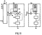
- Fig. 11 shows again another embodiment of the signal processing unit 9 of figure 1, denoted by 9 ⁇ .
- the processing unit 9 ⁇ has switching means 100, and M signal combination units, of which only the first two are shown and have the reference numberals 102 and 103, respectively.
- the inputs 8.1 to 8.2M of the processing unit 9 ⁇ are coupled to the 2M inputs of the switching means 100.
- These means 100 have one output 101 which is coupled to the inputs of all signal combination units. Only the couplings to the inputs 104 and 105 of the combination units 102 and 103 are given.
- the outputs of the M combination units are the outputs 10.1 to 10.M of the processing unit 9 ⁇ .
- Each combination unit has a multiplication unit 106, a memory 107 having 2M storage locations, an adder 108 and an accumulating register 109.
- the switching means 100 are adapted to arrange each time the samples in blocks of 2M samples that occur more or less at the same instant at the 2M inputs 8.1 to 8.2M, each sample at one input, in a serial fashion at the output 101.
- the contents of the memory 107 for the combination unit 102 and 103 are given in figure 11.
- the multiplication factors ⁇ 11, to ⁇ 1.2M and ⁇ 21 to ⁇ 2.2M contained in the said memories equal the corresponding factors in the processing unit 9 in figure 7.
- the processing unit 9 and 9 ⁇ should of course carry out the same processing on the signals applied to their inputs.
- the memory 107 is controlled in such a way that it supplies the factor ⁇ 11 to the input 111 of the multiplication unit 106, when the switching means 100 supply the sample that occurred at the input 8.1 to the input 112 of the unit 106.
- the contents of the register 109 is zero at this moment, so that after the multplication the result is stored in the register 109.
- the sample that occurred at the input 82 is applied to the input 112 and the factor ⁇ 12 is applied to the input 111 of the unit 106, and they are multiplied with each other.
- the adder 108 By means of the adder 108, the result of this multiplication, that is applied to the input 113 of adder 108, is added to the contents of the register 109, that is applied to the input 114 of the adder 108, and stored in the register 109.
- This processing continues for the multiplication with all the 2M factors contained in the memory 107. Moreover this processing is carried out in parallel in the other combination units, such as unit 103.
- processing unit 12 can be built up in the same way.
- Such processing unit comprises 2M signal combination units, such as the unit 102 in figure 11, will the difference that the memory 107 now contains M factors a11 to ⁇ 1.M′ or ⁇ 21 to ⁇ 2.M for the memory 107 in the unit 103.
- switching means 100 are different, in that they have M inputs 12.1 to 12.M and that they arrange each time the samples in consecutive blocks of M samples that occur more or less at the same instant at the M inputs 12.1 to 12.M, each sample at one input, in a serial fash and the output 101. Further the register 109 is now set to zero after the M-th multiplication.
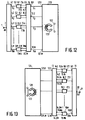
- Figures. 12 and 13 show a transmission via magnetic record carriers.
- Figure 12 shows a digital signal recording apparatus, which includes the transmitter as shown in figure 1.
- the apparatus further includes recording means 120 having M inputs 121.1 to 121.M, each one coupled to a corresponding one of the M outputs of the signal processing unit 9.
- the apparatus is for recording a digital audiosignal to be applied to the input 1 on a magnetic record carrier 122 by means of at least one magnetic recording head 123.
- the recording means 120 can be an RDAT type of recording means, which uses the helical scan recording principle to record the signal s1 to s M in slank tracks lying next to each other on the record carrier, in the form of a magnetic tape. In that case it might be necessary for the recording means 120 to incorporate means to realize a parallel-to-serial conversion on the signal applied to the inputs 121.1 to 121.M.
- the recording means 120 can equally well be an SDAT type of recording means, in which the signals s1 to s m to be recorded are divided over a number of tracks, the said number of tracks not necessarily being equal to M, lying in parallel on, and in the length direction of the record carrier. Also in this case it might be necessary to realize parallel-to-serial conversion on the signals, e.g. if the number of tracks is less than M.
- RDAT and SDAT type of recording means are well known in the art and can e.g. be found in the book "The art of digital audio" by J. Watkinson, Focal press, London, 1988. Therefore no further explanation is needed.
- Figure 13 shows a digital reproduction apparatus, which includes the receiver as shown in figure 1.
- the apparatus further includes reproducing means 124 having M outputs 125.1 to 125.M, each one coupled to one of the inputs 12.1 to 12.M of the other signal processing unit 13.
- the apparatus is for reproducing the digital signal, as it is recorded on the record carrier 122 by means of the apparatus of figure 12. Therefore the reproducing means 124 comprise at least one read head 126.
- the reproducing means can be an RDAT or SDAT type reproducing means.
- RDAt or SDAT type reproducing means For a further explanation of the reproducing means in the form of an RDAt or SDAT type reproducing means, reference is made to the previously mentioned books of J. Watkinson.
- the invention is not limited to the embodiments disclosed herein.
- The-invention equally applies to those embodiments which differ from the embodiments shown in respects which are not relevant to the invention.
- the present invention can be equally well applied in apparatuses such as they are described in the Netherlands Patent applications 88.02.769 and 89.01.032, which both correspond to European patent application no 372601 and in which at least two signals are combined into a composite signal, are transmitted, and are split up in at least two signals at the receiver side.
Landscapes
- Engineering & Computer Science (AREA)
- Physics & Mathematics (AREA)
- General Physics & Mathematics (AREA)
- Computer Networks & Wireless Communication (AREA)
- Signal Processing (AREA)
- Discrete Mathematics (AREA)
- Mathematical Physics (AREA)
- Computer Hardware Design (AREA)
- Multimedia (AREA)
- Theoretical Computer Science (AREA)
- Compression, Expansion, Code Conversion, And Decoders (AREA)
- Transmission Systems Not Characterized By The Medium Used For Transmission (AREA)
- Moving Of The Head To Find And Align With The Track (AREA)
Claims (37)
- Digitales Übertragungssystem mit einem Sender und einem Empfänger, wobei der Sender einen Coder (3,6,9) und der Empfänger einen Decoder (13,16,19) enthält, um ein digitales Signal im Teilband zu codieren, wie z.B. ein digitales Audiosignal mit einer gegebenen Abtastfrequenz FS, wobei der Coder zum Erzeugen einer Anzahl von M Teilbandsignalen mit Abtastfrequenzverringerung auf das digitale Signal anspricht, und das Digitalsignalband in aufeinanderfolgende Teilbänder mit Bandnummern m(1 ≦ m ≦ M) unterteilt, die mit der Frequenz ansteigen, wobei der Decoder auf die M Teilbandsignale zum Aufbauen einer Replik des digitalen Signals anspricht, und die Teilbänder zum Digitalsignalband mit Abtastfrequenzanstieg kombiniert, wobei der Coder (3,6,9) Analysefiltermittel (3,6) und eine Signalverarbeitungseinheit (9) enthält, wobei das Analysefiltermittel M Analysefilter (6.1 bis 6.M) enthält, die je einen Eingang und zwei Ausgänge besitzen, wobei die 2M Ausgänge der Filter mit 2M Ausgängen des Analysefiltermittels zur Auslieferung von 2M Ausgangssignalen mit einer Abtastfrequenz von FS/M verbunden sind, wobei jedes Analysefilter (6.1) zum Durchführen von zwei verschiedenen Filterungen an dem an seinen Eingang (5.1) gelegten Signal und zum Ausliefern jedes der zwei verschiedenen filtrierten Ausführungen dieses Ausgangssignals an einen entsprechenden Ausgang der beiden Ausgänge (7.1a, 7.1b) ausgelegt ist, wobei jeder der 2M Filterausgänge an einen entsprechenden Eingang der 2M Eingänge (8.1 bis 8.2M) der Signalverarbeitungseinheit (9) angeschlossen ist, wobei die Verarbeitungseinheit mit M Ausgängen (10.1 bis 10.M) an M Ausgänge des Coders zum Ausliefern der M Teilbandsignale angeschlossen ist, wobei die Signalverarbeitungseinheit zur Lieferung von Ausgangssignalen an jeden der M Ausgänge ausgelegt ist, wobei ein Ausgangssignal eine Kombination wenigstens einer Anzahl von Eingangssignalen an seine 2M Eingänge ist, wobei der Decoder (13,16,19) eine andere Signalverarbeitungseinheit (13) und ein Synthesefiltermittel (16, 19) besitzt, wobei die andere Signalverarbeitungseinheit mit M Eingängen (12.1 bis 12.M) zum Empfangen der M Teilbandsignale und mit 2M Ausgängen (14.1 bis 14.2M) versehen ist, wobei das Synthesefiltermittel M Synthesefilter (16.1 bis 16.M) besitzt, die je 2 Eingänge enthalten, und mit einem Ausgang (20) an den Decoderausgang angeschlossen ist, wobei die andere Signalverarbeitungseinheit (13) zum Erzeugen eines Ausgangssignals an jedem seiner 2M Ausgänge ausgelegt ist, wobei ein Ausgangssignal eine Kombination wenigstens einer Anzahl von Eingangssignalen zu seinen M Eingängen ist, wobei jedes Ausgängepaar (14.1, 14.2) der anderen Signalverarbeitungseinheit an ein Paar von zwei Eingängen (15.1a, 15.1b) eines entsprechenden Filters der M Synthesefilters (16.1 bis 16.M) angeschlossen ist, wobei jedes Synthesefilter (16.1) einen Ausgang (17.1) besitzt, wobei jedes Synthesefilter zur Durchführung verschiedener Filterungen an den an die beiden Eingängen angelegten zwei Signalen und zur Lieferung einer Kombination der zwei gefiltereten Signale an seinem Ausgang ausgelegt ist, wobei jeder Ausgang an den Ausgang des Synthesefiltermittels zur Lieferung der Replik des digitalen Signals mit einer Abtastfrequenz von FS verbindbar ist, daß der Coder zum Verteilen des Digitalsignalbandes in aufeinanderfolgende Teilbänder B₁, B₂, ....) mit etwa gleichen Bandbtreiten ausgelegt ist, dadurch gekennzeichnet, daß die Koeffizienten jedes der Analyse- und Synthesefilter aus den Koeffizienten eines Standardfilters (H(f)) mit einer Tiefpaßfilterkennlinie mit einer Bandbreite von etwa gleich der Hälfte der Bandbreite der Teilbänder abgeleitet sind, und daß die Koeffizienten jedes der Analyse- und Synthesefilter aus den Koeffizienten eines Standardfilters mit einer Tiefpaßfilterkennlinie mit einer Bandbreite etwa gleich der Hälfte der Bandbreite der Teilbänder abgeleitet sind, und daß die Koeffizienten für die Analysefilter und die Synthesefilter von einem Standardfilter mit einer ungeraden Anzahl Koeffizienten abgeleitet sind, daß M eine gerade Anzahl ist und daß zum Gleichmachen der Anzahl Koeffizienten des Standardfilters zu der Anzahl Multiplikationsfaktoren jedes der Analysefilter und Synthesefilter, zu der Reihe von Koeffizienten des Standardfilters Nullen hinzugefügt werden.
- Digitales Übertragungssystem nach Anspruch 1, dadurch gekennzeichnet, daß das Analysefiltermittel (3,6) eine erste Einheit (3) mit einem an den Codereingang (1) angeschlossenen Eingang (2) zum Empfangen der Abtastungen des digitalen Signals und mit M Ausgängen (4.1 bis 4.M) zum Ausgeben von M Ausgangssignalen mit einer Abtastfrequenz von FS/M enthält, wobei die erste Einheit (3) zum jeweiligen Ausgeben von M Abtastungen ausgelegt ist, die in aufeinanderfolgenden Blöcken von M Abtastungen des digitalisierten Eingangssignals derart erscheinen, daß die m. Abtastung jedes Blocks an den m. Ausgang gelangt, wobei jeder der M Ausgänge mit einem Eingang eines entsprechenden Filters von M Analysefiltern (6.1 bis 6.M) gekoppelt ist, wobei das Synthesefiltermittel (16, 19) außerdem eine zweite Einheit (19) mit M Eingängen (18.1 bis 18.M) enthält, die mit den M Ausgängen der Synthesefilter (16.1 bis 16.M) und ein Ausgang (20) mit dem Ausgang (21) des Synthesefiltermittels gekoppelt sind, die zweite Einheit (19) jedesmal beim Vorliegen der Abtastungen an den M Eingängen zum Ordnen von M Abtastungen eine nach der anderen in einem Block aufeinanderfolgender Blöcke von M Abtastungen derart ausgelegt ist, daß die am m. Eingang empfangenen Abtastungen sich an der m. Stelle in den aufeinanderfolgenden Blöcken befinden, wonach die Blöcke an den Ausgang (20) gelangen.
- Digitales Übertragungssustem nach Anspruch 1 oder 2, dadurch gekennzeichnet, daß jedes Analysefilter (6.M) eine Reihenschaltung (31) von Verzögerungsabschnitten mit gleicher Verzögerung (T) enthält, wobei der Filtereingang an den Eingang des ersten Verzögerungsabschnitts (32.1) angeschlossen ist, Ausgänge wenigstens einer Anzahl ungeradzahliger Verzögerungsabschnitte (32.1, 32.3, ...) in der Reihenschaltung an entsprechende Eingänge einer ersten Signalverknüpfungseinheit (33) angeschlossen sind, Ausgänge wenigstens einer Anzahl geradzahliger Verzögerungsabschnitte (32.2, 32.4, ...) in der Reihenschaltung an entsprechende Eingänge einer zweiten Signalverknüpfungseinheit (34) angeschlossen sind, Ausgänge der ersten und der zweiten Signalverknüpfungseinheit an den ersten bzw. den zweiten Ausgang (35.1, 35.2) des Filters angeschlossen sind.
- System nach Anspruch 1 oder 2, dadurch gekennzeichnet, daß jedes Analysefilter zwei Reihenschaltungen (40, 41) von Verzögerungsabschnitten mit gleichem Verzögerungsbetrag (2T) enthält, wobei der Eingang (30) des Filters an die Eingänge (44.1, 45.1) der ersten und wenigstens eine Anzahl anderer Verzögerungsabschnitte (44.2, 45.2) in jeder Reihenschaltung und die Ausgänge der beiden Reihenschaltungen an den ersten bzw. zweiten Filterausgang (35.1, 35.2) angeschlossen sind, wobei ein weiterer Verzögerungsabschnitt (48) mit einer Verzögerung (T) gleich der Hälfte der Verzögerung der Verzögerungsabschnitte in den Reihenschaltungen in dem Signalweg vom Eingang (30) zum zweiten Filterausgang (35.1) verbunden ist, wobei der weitere Verzögerungsabschnitt nicht in den Signalweg vom Eingang (30) zum ersten Filterausgang (35.2) aufgenommen ist.
- System nach Anspruch 3, dadurch gekennzeichnet, daß Ausgänge ungeradzahliger Verzögerungsabschnitte mit Eingängen der ersten Signalverknüpfungseinheit (33) allein gekoppelt ist, und daß Ausgänge geradzahliger Verzögerungsabschnitte mit Eingängen der zweiten Signalverknüpfungseinheit allein gekoppelt sind.
- System nach Anspruch 3 oder 5, dadurch gekennzeichnet, daß die Ausgänge der Verzögerungsabschnitte mit den entsprechenden Eingängen der ersten oder zweiten Signalverknüpfungseinheit über Vervielfachungseinheiten (a1m, a2m, ...) gekoppelt sind.
- System nach Anspruch 3, 5 oder 6, dadurch gekennzeichnet, daß der Filtereingang (30) mit einem Eingang der zweiten Signalverknüpfungseinheit (34) über eine Vervielfachungseinheit (a0m) gekoppelt ist.
- System nach Anspruch 4, dadurch gekennzeichnet, daß der Filtereingang (30) mit den Eingängen der Verzögerungsabschnitte (40, 41) über Vervielfachungseinheiten (b1m, c1m) gekoppelt sind.
- System nach Anspruch 8, dadurch gekennzeichnet, daß ein Ausgang einer Vervielfachungseinheit (b2m) mit einem ersten Eingang einer Signalverknüpfungseinheit (46.1) gekoppelt, ein zweiter Eingang der Signalverknüpfungseinheit mit einem Ausgang eines Verzögerungsabschnitts (44.1) in einer der zwei Reihenschaltungen und ein Ausgang der Signalverknüpfungseinheit mit einem Eingang des folgenden Verzögerungsabschnitts (44.2) in der betreffenden Reihenschaltung (40) gekoppelt sind.
- System nach Anspruch 4, 8 oder 9, dadurch gekennzeichnet, daß der Filtereingang (30) mit dem ersten und dem zweiten Ausgang über einen ersten bzw. einen zweiten Signalweg gekoppelt ist, wobei diese ersten und zweiten Signalwege je eine Vervielfachungseinheit (bAm, cqm) enthalten und zur ersten bzw. zweiten Reihenschaltung parallelgeschaltet sind.
- System nach Anspruch 1 oder 2, dadurch gekennzeichnet, daß jedes Synthesefilter zwei Reihenschaltungen (52, 53) von Verzögerungsabschnitten mit gleichem Verzögerungsbetrag (2T) enthält, wobei die ersten und zweiten Filtereingänge (50.1, 50.2) mit einem Eingang des ersten Verzögerungsabschnitts der ersten bzw. der zweiten Reihenschaltung verbunden sind, Ausgänge wenigstens einer Anzahl von Verzögerungsabschnitten in der ersten Reihenschaltung mit entsprechenden Eingängen einer Signalverknüpfungseinheit (54) verbunden sind, Ausgänge wenigstens einer Anzahl von Verzögerungsabschnitten in der zweiten Reihenschaltung ebenfalls mit entsprechenden Eingängen der Signalverknüpfungseinheit gekoppelt sind, ein Ausgang (60) der Signalverknüpfungseinheit an den Filterausgang (51) angeschlossen ist, ein weiterer Verzögerungsabschnitt (55) mit einer Verzögerung (T) gleich der Hälfte der Verzögerung der Verzögerungsabschnitte in den Reihenschaltungen in den Signalweg vom zweiten Eingang (50.2) zum Filterausgang (51) aufgenommen ist, und der weitere Verzögerungsabschnitt nicht in den Signalweg vom ersten Eingang (50.1) zum Filterausgang (51) aufgenommen ist.
- System nach Anspruch 1 oder 2, dadurch gekennzeichnet, daß jedes Synthesefilter eine Reihenschaltung (65) von Verzögerungsabschnitten mit gleicher Verzögerung (T) enthält, der erste Filtereingang (50.2) an Eingänge wenigstens einer Anzahl ungeradzahliger Verzögerungsabschnitte (66.1, 66.3,...) in der Reihenschaltung gekoppelt sind, der zweite Filtereingang (50.1) mit Eingängen wenigstens einer Anzahl geradzahliger Verzögerungsabschnitte (66.2, 66.4, ...) in der Reihenschaltung gekoppelt sind und der Ausgang des letzten Verzögerungsabschnitts (66.n) an den Filterausgang (15) angeschlossen ist.
- System nach Anspruch 12, dadurch gekennzeichnet, daß der erste Filtereingang an Eingänge nur ungeradzahliger Verzögerungsabschnitte angeschlossen und der zweite Filtereingang mit Eingängen nur geradzahliger Verzögerungsabschnitte gekoppelt ist.
- System nach Anspruch 11, dadurch gekennzeichnet, daß die Ausgänge der Verzögerungsabschnitte der ersten und zweiten Reihenschaltungen mit entsprechenden Eingängen der Signalverknüpfungseinheit über Vervielfachungseinheiten (22m, d3m, e2m, e3m) gekoppelt sind.
- System nach Anspruch 11 oder 14, dadurch gekennzeichnet, daß der erste und der zweite Filtereingang (50.2, 50.1) ebenfalls mit entsprechenden Eingängen der Signalverknüpfungseinheit über Vervielfachungseinheiten (d₁m, e1m) gekoppelt sind.
- System nach Anspruch 12 oder 13, dadurch gekennzeichnet, daß die Filtereingange über Vervielfachungseinheiten (a1m, a2m, ...) mit den Eingängen der Verzögerungsabschnitte gekoppelt sind.
- System nach Anspruch 16, dadurch gekennzeichnet, daß ein Ausgang einer Vervielfachungseinheit (67.3) mit einem ersten Eingang einer Signalverknüpfungseinheit gekoppelt, ein zweiter Eingang der Signalverknüpfungseinheit mit einem Ausgang eines Verzögerungsabschnitts (66.2) in der Reihenschaltung und ein Ausgang der Signalverknüpfungseinheit mit einem Eingang des folgenden Verzögerungsabschnitts (66.3) in der betreffenden Reihenschaltung gekoppelt sind.
- System nach Anspruch 12, 13, 16 oder 17, dadurch gekennzeichnet, daß der zweite Filtereingang (50.2) über einen Signalweg mit dem Filterausgang (51) gekoppelt ist, dieser Signalweg eine Vervielfachungseinheit (a0m) enthält und zur Reihenschaltung parallelgeschaltet ist.
- System nach Anspruch 1 oder 2, dadurch gekennzeichnet, daß die Signalverarbeitungseinheit M Signalverknüpfungseinheiten (70.1, 70.2, ...) enthält, die mit je einem Ausgang an einen entsprechenden Ausgang (74.1) der M Ausgänge der Signalverarbeitungseinheit angeschlossen sind, daß für jede Signalverknüpfungseinheit wenigstens eine Anzahl von Eingängen (71.1, 71.2, ...) von den 2M Eingängen der Verarbeitungseinheit mit entsprechenden Eingängen dieser Signalverknüpfungseinheit (70.1) über entsprechende Vervielfachungseinheiten (72.11, 72.12) gekoppelt sind.
- System nach Anspruch 1 oder 2, dadurch gekennzeichnet, daß die andere Signalverarbeitungseinheit 2M Signalverknüpfungseinheiten (70.1, 70.2, ...) enthält, die mit je einem Ausgang an einen entsprechenden Ausgang der 2M Ausgänge der Verarbeitungseinheit gekoppelt sind, daß für jede Signalverknüpfungseinheit (74.i) wenigstens eine Anzahl von Eingängen (71.1, 71.2, ...) der M Eingänge der Verarbeitungseinheiten an entsprechende Eingänge dieser Signalverknüpfungseinheit (70.1) über entsprechende Vervielfachungseinheiten (72.11, 72.12) angeschlossen sind.
- System nach Anspruch 1 oder 2, dadurch gekennzeichnet, daß die zwei Ausgänge jedes Analysefilters mit ihren entsprechenden Eingängen der Signalverarbeitungseinheit über eine entsprechende Signalverstärkungseinheit (80.1, 81.1) gekoppelt sind, wobei beide Verstärkungseinheiten zum Verstärken der an ihre Eingänge angelegten Signale um denselben komplexen Wert (K₁) ausgelegt sind.
- System nach Anspruch 21, dadurch gekennzeichnet, daß die komplexen Werte (K₁, K₂, ...) für an verschiedene Analysefilter angeschlossene Verstärkungseinheiten abweichen.
- System nach Anspruch 21 oder 22, dadurch gekennzeichnet, daß jeder Ausgang (86.1) der Verarbeitungseinheit an seinen entsprechenden Coderausgang (10.1) über eine Reihenschaltung einer Signalverstärkungseinheit und einen Realwertbestimmer gekoppelt ist, wobei die Signalverstärkungseinheit zum Verstärken des an seinen Eingang gelegten Signals um einen komplexen Wert ausgelegt ist.
- System nach Anspruch 1 oder 2, dadurch gekennzeichnet, daß die zwei Ausgänge (93.1, 93.2) jedes Ausgängepaars der anderen Signalverarbeitungseinheit (13′) mit ihrem entsprechenden Eingang eines Synthesefilters (16.1) über eine entsprechende Signalverstärkungseinheit (94.1, 95.1) gekoppelt sind, wobei beide Verstärkungseinheiten zum Verstärken der an ihre Eingänge gelegten Signale um denselben komplexen Wert (K₁′)ausgelegt sind.
- System nach Anspruch 24, dadurch gekennzeichnet, daß die komplexen Werte (K₁′, K₂′) für Verstärkungseinheiten, die mit verschiedenen Synthesefiltern (16.1, 16.2) gekoppelt sind, abweichen.
- System nach Anspruch 1 oder 2, dadurch gekennzeichnet, daß die M Eingänge des Decoders an ihren entsprechenden Eingang der M Eingänge der anderen Verarbeitungseinheit über eine Signalverstärkungseinheit angeschlossen sein, wobei die Signalverstärkungseinheit (90.1, 90.2, ...) zum Verstärken des an seinen Eingang gelegten Signals um einen weiteren komplexen Wert (V₁′, V₂′, ...) ausgelegt ist.
- System nach Anspruch 23 oder 26, dadurch gekennzeichnet, daß die anderen komplexen Werte voneinander abweichen.
- System nach einem oder mehreren der Ansprüche 6 bis 10 sowie 14 bis 20, dadurch gekennzeichnet, daß diejenigen Vervielfachungseinheiten, deren Vervielfachungsfaktoren zum Vervielfachen ihrer Eingangssignale gleich eins sind, abkömmlich sind.
- System nach einem der Ansprüche 6 bis 10 und 14 bis 20, dadurch gekennzeichnet, daß diejenigen Kopplungen, die eine Vervielfachungseinheit enthalten, deren Vervielfachungsfaktor zum Vervielfachen ihres Eingangssignals gleich Null ist, abkömmlich sind.
- System nach Anspruch 1 oder 2, dadurch gekennzeichnet, daß die Signalverarbeitungseinheit (9˝) ein Schaltmittel (100) und M Signalverknüpfungseinheiten (102) enthält, wobei jeder der 2M Eingänge (8.1 bis 8.2M) der Signalverarbeitungseinheit an einen entsprechenden Eingang von 2M Eingängen des Schaltmittels angeschlossen sind, wobei der eine Ausgang (101) des Schaltmittels mit einem Eingang jedes der M Signalverknüpfungseinheiten (102) gekoppelt ist, wobei jede Signalverknüpfungseinheit eine Vervielfachungseinheit (106) enthält, wobei ein Speicher (107) mit 2M Speicherstellen, einen Addierer (108) und ein Saldierregister (109) besitzt, wobei der Eingang der Signalverknüpfungseinheit und ein Speicherausgang an einen ersten bzw. einen zweiten Eingang (112 bzw. 111) der Vervielfachungseinheit angeschlossen sind, ein Ausgang der Vervielfachungseinheit (106) und das Saldierregister (109) an einen ersten bzw. einen zweiten Eingang (113, 114) des Addierers (108) angeschlossen sind, ein Ausgang des Addierers mit einem Eingang des Registers gekoppelt ist, der Ausgang des Registers (109) der m. Signalverknüpfungseinheit mit dem m. Ausgang (10.m) der Signalverarbeitungseinheit (9˝) gekoppelt ist, das Schaltmittel (100) zum zyklischen Koppeln jedes seiner 2M Eingänge (8.1 bis 8.2M) mit seinem Ausgang (10i) ausgelegt ist, um jeweils die Abtastungen in Blöcken von 2M Abtastungen, die an seinen 2M Eingängen erscheinen, je eine Abtastung an jeden Eingang, seriell seinem Ausgang zuzuführen, der Speicher (107) 2M Vervielfachungsfaktoren (α) enthält und zum Zuleiten der 2M Vervielfachungsfaktoren auf kreisförmige Weise zu seinem Ausgang derart ausgelegt ist, daß der i. Vervielfachungsfaktor seinem Ausgang zugeleitet wird, wenn das Schaltmittel (100) die i. Abtastung der 2M Abtastung in einem Block seinem Ausgang zuführt, worin i von 1 bis 2M lauft, der Addierer (108) und das Saldierregister (109) zum Addieren des Ergebnisses der i. Multiplikation beim Inhalt im Saldierregister aufzählt, und das Saldierregister außerdem zum Ausgeben seines Inhalts nach dem 2M. Vervielfachungsschritt an den Ausgang (10.m) der Signalverknüpfungseinheit und zum anschließenden Nullrückstellen seines Inhalts ausgelegt ist.
- System nach Anspruch 1 oder 2, dadurch gekennzeichnet, daß die andere Signalverarbeitungseinheit ein Schaltmittel (100) und 2M Signalverknüpfungseinheiten (102) enthält, wobei jeder der M Eingänge der anderen Signalverarbeitungseinheit an einen entsprechenden Eingang von M Eingängen des Schaltmittels angeschlossen ist, der einen Ausgang des Schaltmittels mit einem Eingang jedes der 2M Signalverknüpfungseinheiten gekoppelt ist, jede Signalverknüpfungseinheit eine Vervielfachungseinheit (106) enthält, ein Speicher mit M Speicherstellen, einen Addierer (108) und ein Saldierregister (109) besitzt, wobei der Eingang der Signalverknüpfungseinheit und ein Speicherausgang an einen ersten bzw. einen zweiten Eingang der Vervielfachungseinheit (106) angeschlossen sind, ein Ausgang der Vervielfachungseinheit und das Saldierregister an einen ersten bzw. einen zweiten Eingang des Addierers angeschlossen sind, ein Ausgang des Addierers mit einem Eingang des Registers gekoppelt ist, der Ausgang des Registers der i. Signalverknüpfungseinheit mit dem i. Ausgang der anderen Signalverarbeitungseinheit qekoppelt ist, worin i von 1 bis 2M läuft, das Schaltmittel züm zyklischen Koppeln jedes seiner M Eingänge mit seinem Ausgang ausgelegt ist, um jeweils die Abtastungen in Blöcken von M Abtastungen, die an seinen M Eingängen erscheinen, je eine Abtastung an jeden Eingang, seriell seinem Ausgang zuzuführen, der Speicher M Vervielfachungsfaktoren enthält und zum Zuleiten der M Vervielfachungsfaktoren auf kreisförmige Weise zu seinem Ausgang derart ausgelegt ist, daß der m. Vervielfachungsfaktor seinem Ausgang zugeleitet wird, wenn das Schaltmittel die m. Abtastung der M Abtastungen in einem Block seinem Ausgang zuführt, der Addierer und das Saldierregister zum Addieren des Ergebnisses der m. Multiplikation beim Inhalt im Saldierregister aufzählt, und das Saldierregister außerdem zum Ausgeben seines Inhalts nach dem M. Vervielfachungsschritt an den Ausgang (101) der Signalverknüpfungseinheit und zum anschließenden Nullrückstellen seines Inhalts ausgelegt ist.
- Coder zur Teilbandcodierung eines digitalen Signals, wi eines digitalen Audiosignals mit einer bestimmten Abtastrate FS, wobei der Coder auf das Digitale Signal anspricht zum Erzeugen einer Anzahl M Teilbandsignale mit Abtastratenverringerung, wobei der Coder das digitale Signalband in aufeinanderfolgende Teilbänder mit Bandnummern m(1 ≦ m ≦ M), die mit der Frequenz ansteigen, aufteilt, wobei der Coder (3,6,9) Analysefiltermittel (3,6) und eine Signalverarbeitungseinheit (9) enthält, das Analysefiltermittel M Analysefilter (6.1 bis 6.M) enthält, die je einen Eingang und zwei Ausgänge besitzen, wobei die 2M Ausgänge auf den Filtern mit 2M Ausgängen des Analysefiltermittels zur Auslieferung von 2M Ausgangssignalen mit einer Abtastrate von FS/M verbunden sind, wobei jedes Analysefilter (6.1) zum Durchführen von zwei verschiedenen Filterungen an dem an seinen Eingang (5.1) gelegten Signal und zum Ausliefern jedes der zwei verschiedenen filtrierten Ausführungen dieses Ausgangssignals an einen entsprechenden Ausgang der beiden Ausgänge (7.1a, 7.2b) ausgelegt ist, wobei jeder der 2M Filterausgänge an einen entsprechenden Eingang der 2M Eingänge (8.1 bis 8.2M) einer Signalverarbeitungseinheit (9) angeschlossen ist, wobei die Verarbeitungseinheit mit M Ausgängen (10.1 bis 10.M) an M Ausgänge des Coders zum Ausliefern der M Teilbandsignale angeschlossen ist, wobei die Signalverarbeitungseinheit zur Lieferung von Ausgangssignalen an jeden der M Ausgänge ausgelegt ist, wobei ein Ausgangssignal eine Kombination wenigstens einer Anzahl von Eingangssignalen an seine 2M Eingänge ist, wobei der Coder dazu vorgesehen ist, das digitale Signalband in aufeinanderfolgende Teilbänder (B₁, B₂, ...) mit nahezu gleichen Bandbreiten aufzuteilen, dadurch gekennzeichnet, daß die Koeffizienten jedes der Analysefilter aus den Koeffizienten eines Standardfilters (H(f)) mit einer Tiefpaßfilterkennlinie mit einer Bandbreite etwa gleich der Hälfte der Bandbreite der Teilbänder abgeleitet sind, und daß die Koeffizienten für die Analysefilter von einem Standardfilter mit einer ungeraden Anzahl Koeffizienten abgeleitet sind, daß M eine gerade Anzahl ist und daß zum Gleichmachen der Anzahl Koeffizienten des Standardfilters zu der Anzahl Multiplikationsfaktoren jedes der Analysenfilter und Synthesefilter, zu der Reihe von Koeffizienten des Standardfilters Nullen hinzugefügt werden.
- Decoder zum Decodieren von M Teilbandsignals, die durch Teilbandcodierung eines digitalen Signals erhalten worden sind durch Aufteilung des digitalen Signalbandes in etwa gleiche Bandbreiten, wobei der Decoder auf die M Teilbandsignale zum Aufbauen einer Replik des digitalen Signals anspricht und die Teilbänder zum Digitalsignalband mit Abtastgeschwindigkeitsanstieg kombiniert, wobei der Decoder (13,16,19) eine Signalverarbeitungseinheit (13) und ein Synthesefiltermittel (16,19) besitzt, wobei die Signalverarbeitungseinheit mit M Eingängen (12.1 bis 12.M) zum Empfangen der M Teilbandsignale und mit 2M Ausgängen (14.1 bis 14.M) versehen ist, wobei das Synthesefiltermittel M Synthesefilter (16.1 bis 16.M) besitzt, die je 2 Eingänge enthalten, und mit einem Ausgang (20) an den Decoderausgang angeschlossen ist, wobei die andere Signalverarbeitungseinheit (13) zum Erzeugen eines Ausgangssignals an jedem seiner 2M Ausgänge ausgelegt ist, wobei ein Ausgangssignal eine Kombination wenigstens einer Anzahl von Eingangssignalen zu seinen M Eingängen ist, wobei jedes Ausgängepaar (14.1 bis 14.2) der Signalverarbeitungseinheit an ein Paar von zwei Eingängen (15.1a, 15.1b) eines entsprechenden Filters der M Synthesefilter (16.1 bis 16.M) angeschlossen ist, wobei jedes Synthesefilter (16.1) einen Ausgang (17.1) besitzt, wobei jedes Synthesefilter zur Durchführung verschiedener Filterungen an den den beiden Eingängen zugeführten zwei Signalen und zur Lieferung einer Kombination der zwei gefilterten Signalen an seinen Ausgang ausgelegt ist, wobei jeder Ausgang an den Ausgang des Synthesefiltermittels zur Lieferung der Replik des digitalen Signals mit einer Abtastrate von FS verbindbar ist, dadurch gekennzeichnet, daß die Koeffizienten jedes der Synthesefilter aus den Koeffizienten eines Standardfilters mit einer Tiefpaßfilterkennlinie mit einer Bandbreite etwa gleich der Hälfte der Bandbreite der Teilbänder abgeleitet sind, und daß die Koeffizienten für die Synthesefilter von einem Standardfilter mit einer ungeraden Anzahl Koeffizienten abgeleitet sind, daß M eine gerade Anzahl ist und daß zum Gleichmachen der Anzahl Koeffizienten des Standardfilters zu der Anzahl Multiplikationsfaktoren jedes der Analyse- und Synthesefilter, zu der Reihe von Koeffizienten des Standardfilters Nullen hinzugefügt werden.
- Sender zum Übertragen eines digitalen Signals mit einem Coder (3,6,9) zur Teilbandcodierung des digitalen Signals nach Anspruch 32.
- Empfänger zum Empfangen eines digitalen Signals, das bei der Übertragung in eine Anzahl von M Teilbandsignale aufgeteilt worden ist durch Teilung des digitalen Signalbandes in Teilbänder etwa gleicher Bandbreite mit Abtastratenverringerung mit einem Decoder nach Anspruch 33.
- Digitales Audiosignal-Aufzeichnungsgerät zum Aufzeichnen eines digitalen Audiosignals auf einem Aufzeichnungsträger, mit dem Sender nach Anspruch 34, dadurch gekennzeichnet, daß im Gerät außerdem Aufzeichnungsmittel (120) mit M Eingängen (121.1 bis 121.M) vorgesehen sind, wobei jeder der M Eingänge mit einem entsprechenden Ausgang der M Ausgänge (10.1 bis 10.M) der Signalverarbeitungseinheit (9) gekoppelt ist, wobei die Aufzeichnungsmittel zum Einschreiben der M Teilbandsignale zu seinen M Eingängen in eine Spur auf dem Aufzeichnungsträger (122) ausgelegt ist.
- Digitales Audiosignal-Wiedergabegerät zum Auslesen eines digitalen Audiosignals aus einem Aufzeichnungsträger, mit dem Empfänger nach Anspruch 35, dadurch gekennzeichnet, daß im Gerät außerdem Wiedergabemittel (124) mit M Ausgängen (125.1 bis 125.M) vorgesehen sind, wobei jeder der M Ausgänge mit einem entsprechenden Eingang der M Eingänge (12.1 bis 12.M) der Signalverarbeitungseinheit (13) gekoppelt ist, wobei die Wiedergabemittel zum Auslesen der M Teilbandsignale aus einer Spur auf dem Aufzeichnungsträger (122) ausgelegt ist.
Priority Applications (1)
| Application Number | Priority Date | Filing Date | Title |
|---|---|---|---|
| EP90201369A EP0400755B1 (de) | 1989-06-02 | 1990-05-30 | Digitales Übertragungssystem unter Verwendung der Teilbandkodierung eines digitalen Signals |
Applications Claiming Priority (3)
| Application Number | Priority Date | Filing Date | Title |
|---|---|---|---|
| EP89201408 | 1989-06-02 | ||
| EP89201408A EP0400222A1 (de) | 1989-06-02 | 1989-06-02 | Digitales Übertragungssystem unter Verwendung der Teilbandkodierung eines digitalen Signals |
| EP90201369A EP0400755B1 (de) | 1989-06-02 | 1990-05-30 | Digitales Übertragungssystem unter Verwendung der Teilbandkodierung eines digitalen Signals |
Publications (2)
| Publication Number | Publication Date |
|---|---|
| EP0400755A1 EP0400755A1 (de) | 1990-12-05 |
| EP0400755B1 true EP0400755B1 (de) | 1995-09-06 |
Family
ID=8202401
Family Applications (2)
| Application Number | Title | Priority Date | Filing Date |
|---|---|---|---|
| EP89201408A Withdrawn EP0400222A1 (de) | 1989-06-02 | 1989-06-02 | Digitales Übertragungssystem unter Verwendung der Teilbandkodierung eines digitalen Signals |
| EP90201369A Expired - Lifetime EP0400755B1 (de) | 1989-06-02 | 1990-05-30 | Digitales Übertragungssystem unter Verwendung der Teilbandkodierung eines digitalen Signals |
Family Applications Before (1)
| Application Number | Title | Priority Date | Filing Date |
|---|---|---|---|
| EP89201408A Withdrawn EP0400222A1 (de) | 1989-06-02 | 1989-06-02 | Digitales Übertragungssystem unter Verwendung der Teilbandkodierung eines digitalen Signals |
Country Status (22)
| Country | Link |
|---|---|
| US (1) | US5214678A (de) |
| EP (2) | EP0400222A1 (de) |
| JP (1) | JP3069611B2 (de) |
| KR (1) | KR0181292B1 (de) |
| CN (1) | CN1023280C (de) |
| AR (1) | AR246135A1 (de) |
| AT (1) | ATE127642T1 (de) |
| AU (1) | AU634237B2 (de) |
| BR (1) | BR9002618A (de) |
| CA (1) | CA2017841C (de) |
| CS (1) | CS277633B6 (de) |
| DE (1) | DE69022119T2 (de) |
| DK (2) | DK133290D0 (de) |
| ES (1) | ES2077631T3 (de) |
| FI (1) | FI110349B (de) |
| HK (1) | HK213496A (de) |
| HU (1) | HU206572B (de) |
| MX (1) | MX172514B (de) |
| PL (1) | PL165159B1 (de) |
| PT (1) | PT94224B (de) |
| RU (1) | RU2145464C1 (de) |
| UA (1) | UA37174C2 (de) |
Families Citing this family (40)
| Publication number | Priority date | Publication date | Assignee | Title |
|---|---|---|---|---|
| US5367608A (en) * | 1990-05-14 | 1994-11-22 | U.S. Philips Corporation | Transmitter, encoding system and method employing use of a bit allocation unit for subband coding a digital signal |
| US5287529A (en) * | 1990-08-21 | 1994-02-15 | Massachusetts Institute Of Technology | Method for estimating solutions to finite element equations by generating pyramid representations, multiplying to generate weight pyramids, and collapsing the weighted pyramids |
| US5365553A (en) * | 1990-11-30 | 1994-11-15 | U.S. Philips Corporation | Transmitter, encoding system and method employing use of a bit need determiner for subband coding a digital signal |
| US5274740A (en) * | 1991-01-08 | 1993-12-28 | Dolby Laboratories Licensing Corporation | Decoder for variable number of channel presentation of multidimensional sound fields |
| NL9100173A (nl) * | 1991-02-01 | 1992-09-01 | Philips Nv | Subbandkodeerinrichting, en een zender voorzien van de kodeerinrichting. |
| NL9100285A (nl) * | 1991-02-19 | 1992-09-16 | Koninkl Philips Electronics Nv | Transmissiesysteem, en ontvanger te gebruiken in het transmissiesysteem. |
| KR100263599B1 (ko) * | 1991-09-02 | 2000-08-01 | 요트.게.아. 롤페즈 | 인코딩 시스템 |
| DE69331166T2 (de) * | 1992-02-03 | 2002-08-22 | Koninklijke Philips Electronics N.V., Eindhoven | Übertragung von digitalen Breitbandsignalen |
| TW235392B (de) * | 1992-06-02 | 1994-12-01 | Philips Electronics Nv | |
| TW221836B (de) * | 1992-06-09 | 1994-03-21 | Philips Electronics Nv | |
| US5436940A (en) * | 1992-06-11 | 1995-07-25 | Massachusetts Institute Of Technology | Quadrature mirror filter banks and method |
| DE4227327A1 (de) * | 1992-08-18 | 1994-02-24 | Philips Patentverwaltung | Teilbandechokompensator mit Teilbandcodiereinrichtung |
| JP2509789B2 (ja) * | 1992-08-22 | 1996-06-26 | 三星電子株式会社 | 可聴周波数帯域分割を利用した音響信号歪み補正装置 |
| US6252909B1 (en) * | 1992-09-21 | 2001-06-26 | Aware, Inc. | Multi-carrier transmission system utilizing channels of different bandwidth |
| US5408580A (en) * | 1992-09-21 | 1995-04-18 | Aware, Inc. | Audio compression system employing multi-rate signal analysis |
| KR950008637B1 (ko) * | 1993-04-08 | 1995-08-03 | 삼성전자주식회사 | 부밴드 코딩시스템의 신호처리장치 |
| BE1007617A3 (nl) * | 1993-10-11 | 1995-08-22 | Philips Electronics Nv | Transmissiesysteem met gebruik van verschillende codeerprincipes. |
| DE69435009T2 (de) * | 1993-10-12 | 2008-04-17 | Matsushita Electric Industrial Co., Ltd., Kadoma | Einrichtung zur Verschlüsselung und Entschlüsselung von Audiosignalen |
| EP0678226B1 (de) * | 1993-10-27 | 2003-05-14 | Koninklijke Philips Electronics N.V. | Senden und empfangen einer ersten und einer zweiten signalkomponente |
| US5764698A (en) * | 1993-12-30 | 1998-06-09 | International Business Machines Corporation | Method and apparatus for efficient compression of high quality digital audio |
| WO1995030286A2 (en) * | 1994-05-02 | 1995-11-09 | Philips Electronics N.V. | Encoding system and encoding method for encoding a digital signal having at least a first and a second digital signal component |
| WO1995032556A1 (en) * | 1994-05-19 | 1995-11-30 | Philips Electronics N.V. | Arrangement for determining a signal spectrum of a wideband digital signal and for deriving bit allocation information in response thereto |
| GB9414664D0 (en) * | 1994-07-20 | 1994-09-07 | British Aerospace | Digital signal processing apparatus |
| WO1996008078A1 (en) * | 1994-09-02 | 1996-03-14 | Philips Electronics N.V. | Receiver with quadrature decimation stage, method of processing digital signals |
| DE69525836T2 (de) * | 1994-11-04 | 2002-11-21 | Koninklijke Philips Electronics N.V., Eindhoven | Kodierung und dekodierung eines breitbandigen digitalen informationssignals |
| KR100463462B1 (ko) | 1995-10-24 | 2005-05-24 | 코닌클리케 필립스 일렉트로닉스 엔.브이. | 인코딩,디코딩,및제어신호발생장치및인코딩,디코딩방법 |
| BR9606765A (pt) * | 1995-11-21 | 1997-12-30 | Philips Electronics Nv | Sistema de transmissão digital transmissor e receptor para emprego em um sistema de transmissão suporte de gravação processo para transmissão de um sinal de áudio digital e sinal de transmissão |
| EP0815668B1 (de) * | 1996-01-12 | 2004-10-27 | Koninklijke Philips Electronics N.V. | Sender und verfahren zur übertragung eines breitbandigen, digitalen informationssignals |
| ATE263458T1 (de) * | 1996-02-08 | 2004-04-15 | Koninkl Philips Electronics Nv | Mit einer 5-kanalübertragung und einer 2- kanalübertragung kompatible 7-kanalübertragung |
| KR100472402B1 (ko) * | 1996-04-10 | 2005-07-25 | 코닌클리케 필립스 일렉트로닉스 엔.브이. | 복수의정보신호의부호화장치및방법 |
| CA2184541A1 (en) | 1996-08-30 | 1998-03-01 | Tet Hin Yeap | Method and apparatus for wavelet modulation of signals for transmission and/or storage |
| IL138230A (en) * | 1999-01-07 | 2005-06-19 | Koninkl Philips Electronics Nv | Efficient coding of side information in a lossless encoder |
| US6788751B1 (en) * | 1999-11-24 | 2004-09-07 | Donald W. Moses | Frequency diversity digital wireless system |
| RU2235425C2 (ru) * | 2000-04-21 | 2004-08-27 | Самсунг Электроникс Ко., Лтд. | Способ согласования в режиме гибкой скорости передачи данных в системе передачи данных и устройство для его осуществления |
| ES2280592T3 (es) * | 2001-11-30 | 2007-09-16 | Koninklijke Philips Electronics N.V. | Codificacion de señal. |
| TWI227866B (en) * | 2003-11-07 | 2005-02-11 | Mediatek Inc | Subband analysis/synthesis filtering method |
| KR100830163B1 (ko) | 2005-04-20 | 2008-05-20 | 삼성전자주식회사 | 주파수 오버레이 통신 시스템에서 신호 송수신 장치 및 방법 |
| TWI618350B (zh) | 2009-02-18 | 2018-03-11 | 杜比國際公司 | 用於高頻重建或參數立體聲之複指數調變濾波器組 |
| US8958510B1 (en) * | 2010-06-10 | 2015-02-17 | Fredric J. Harris | Selectable bandwidth filter |
| GB201210373D0 (en) * | 2012-06-12 | 2012-07-25 | Meridian Audio Ltd | Doubly compatible lossless audio sandwidth extension |
Family Cites Families (10)
| Publication number | Priority date | Publication date | Assignee | Title |
|---|---|---|---|---|
| US3781793A (en) * | 1972-04-10 | 1973-12-25 | Ibm | Monolithic array error detection system |
| JPS5654140A (en) * | 1979-10-09 | 1981-05-14 | Sony Corp | Transmission method for pcm signal |
| JPS56119550A (en) * | 1980-02-25 | 1981-09-19 | Sony Corp | Transmission method of pcm signal |
| AU544259B2 (en) * | 1980-04-16 | 1985-05-23 | Sony Corporation | Detecting + correcting errors in digital video signals |
| DE3171311D1 (en) * | 1981-07-28 | 1985-08-14 | Ibm | Voice coding method and arrangment for carrying out said method |
| FR2577084B1 (fr) * | 1985-02-01 | 1987-03-20 | Trt Telecom Radio Electr | Systeme de bancs de filtres d'analyse et de synthese d'un signal |
| IT1184023B (it) * | 1985-12-17 | 1987-10-22 | Cselt Centro Studi Lab Telecom | Procedimento e dispositivo per la codifica e decodifica del segnale vocale mediante analisi a sottobande e quantizzazione vettorariale con allocazione dinamica dei bit di codifica |
| FR2613154A1 (fr) * | 1987-03-24 | 1988-09-30 | France Etat | Systeme de traitement numerique de signal a bancs de filtres |
| NL8700985A (nl) * | 1987-04-27 | 1988-11-16 | Philips Nv | Systeem voor sub-band codering van een digitaal audiosignaal. |
| US4956871A (en) * | 1988-09-30 | 1990-09-11 | At&T Bell Laboratories | Improving sub-band coding of speech at low bit rates by adding residual speech energy signals to sub-bands |
-
1989
- 1989-06-02 EP EP89201408A patent/EP0400222A1/de not_active Withdrawn
-
1990
- 1990-05-30 EP EP90201369A patent/EP0400755B1/de not_active Expired - Lifetime
- 1990-05-30 DK DK133290A patent/DK133290D0/da unknown
- 1990-05-30 ES ES90201369T patent/ES2077631T3/es not_active Expired - Lifetime
- 1990-05-30 DE DE69022119T patent/DE69022119T2/de not_active Expired - Lifetime
- 1990-05-30 CN CN90103390A patent/CN1023280C/zh not_active Expired - Lifetime
- 1990-05-30 DK DK90201369.7T patent/DK0400755T3/da active
- 1990-05-30 AT AT90201369T patent/ATE127642T1/de not_active IP Right Cessation
- 1990-05-30 CS CS902677A patent/CS277633B6/cs not_active IP Right Cessation
- 1990-05-30 RU SU4830377/A patent/RU2145464C1/ru active
- 1990-05-30 FI FI902695A patent/FI110349B/fi active IP Right Grant
- 1990-05-30 UA UA4830377A patent/UA37174C2/uk unknown
- 1990-05-30 CA CA002017841A patent/CA2017841C/en not_active Expired - Lifetime
- 1990-05-31 US US07/532,465 patent/US5214678A/en not_active Expired - Lifetime
- 1990-05-31 AU AU56158/90A patent/AU634237B2/en not_active Expired
- 1990-05-31 PT PT94224A patent/PT94224B/pt not_active IP Right Cessation
- 1990-05-31 HU HU903285A patent/HU206572B/hu unknown
- 1990-06-01 BR BR909002618A patent/BR9002618A/pt not_active IP Right Cessation
- 1990-06-01 PL PL90285436A patent/PL165159B1/pl unknown
- 1990-06-01 MX MX020973A patent/MX172514B/es unknown
- 1990-06-02 KR KR1019900008139A patent/KR0181292B1/ko not_active Expired - Lifetime
- 1990-06-02 JP JP2143303A patent/JP3069611B2/ja not_active Expired - Lifetime
- 1990-06-14 AR AR90317016A patent/AR246135A1/es active
-
1996
- 1996-12-05 HK HK213496A patent/HK213496A/en not_active IP Right Cessation
Also Published As
Similar Documents
| Publication | Publication Date | Title |
|---|---|---|
| EP0400755B1 (de) | Digitales Übertragungssystem unter Verwendung der Teilbandkodierung eines digitalen Signals | |
| USRE42949E1 (en) | Stereophonic audio signal decompression switching to monaural audio signal | |
| US4868868A (en) | Sub-band speech analyzing and synthesizing device | |
| US5235647A (en) | Digital transmission system, an apparatus for recording and/or reproducing, and a transmitter and a receiver for use in the transmission system | |
| HUT54390A (en) | Process for producing monoclonal antibodies reactive against different unique antigenes present in leuchemic/limfomic celles and diagnostical process utilizing them | |
| CN1223992C (zh) | 利用非一致滤波器库的音频编码和解码 | |
| JP3211832B2 (ja) | ディジタルオーディオ信号のプリエコーを低減するためのフィルタリング方法およびその装置 | |
| EP0593850B1 (de) | Verfahren und Einrichtung zur Subbandfilterung eines Stereoaudiosignals | |
| EP0827647B1 (de) | Analyse/synthese-filtersystem mit effizienter mit ungerade gestapelter einseitenband-filterbank unter verwendung der tdac-technik | |
| Sahu et al. | Time domain analysis of two-channel QMF bank | |
| Chen et al. | Optimal design of deconvolution filters for stochastic multirate signal systems | |
| JPH1198023A (ja) | 信号符号化及び復号化装置 | |
| WO1994019791A1 (en) | Improved filter for use in audio compression and decompression systems | |
| JPH0771009B2 (ja) | ディジタルフィルタ回路および帯域分割伝送方式 | |
| JPH06169289A (ja) | 圧縮データ再生装置 | |
| CA2236649A1 (en) | Method and apparatus for encoding of digital signals for transmission and/or storage, and decoding such encoded signals following such transmission and/or storage | |
| Pillai et al. | Almost distortion-free IIR subband filters using a nested structure | |
| US20010016810A1 (en) | Signal reproduction apparatus and method therefor |
Legal Events
| Date | Code | Title | Description |
|---|---|---|---|
| PUAI | Public reference made under article 153(3) epc to a published international application that has entered the european phase |
Free format text: ORIGINAL CODE: 0009012 |
|
| AK | Designated contracting states |
Kind code of ref document: A1 Designated state(s): AT BE CH DE DK ES FR GB GR IT LI NL SE |
|
| 17P | Request for examination filed |
Effective date: 19910718 |
|
| 17Q | First examination report despatched |
Effective date: 19930903 |
|
| RAP1 | Party data changed (applicant data changed or rights of an application transferred) |
Owner name: FRANCE TELECOM Owner name: PHILIPS ELECTRONICS N.V. Owner name: ETAT FRANCAIS REPRESENTE PAR LE MINISTRE DES PTT |
|
| GRAA | (expected) grant |
Free format text: ORIGINAL CODE: 0009210 |
|
| RAP1 | Party data changed (applicant data changed or rights of an application transferred) |
Owner name: FRANCE TELECOM Owner name: PHILIPS ELECTRONICS N.V. Owner name: TELEDIFFUSION DE FRANCE |
|
| AK | Designated contracting states |
Kind code of ref document: B1 Designated state(s): AT BE CH DE DK ES FR GB GR IT LI NL SE |
|
| PG25 | Lapsed in a contracting state [announced via postgrant information from national office to epo] |
Ref country code: NL Free format text: LAPSE BECAUSE OF FAILURE TO SUBMIT A TRANSLATION OF THE DESCRIPTION OR TO PAY THE FEE WITHIN THE PRESCRIBED TIME-LIMIT Effective date: 19950906 Ref country code: AT Effective date: 19950906 Ref country code: GR Free format text: LAPSE BECAUSE OF FAILURE TO SUBMIT A TRANSLATION OF THE DESCRIPTION OR TO PAY THE FEE WITHIN THE PRESCRIBED TIME-LIMIT Effective date: 19950906 Ref country code: BE Effective date: 19950906 |
|
| REF | Corresponds to: |
Ref document number: 127642 Country of ref document: AT Date of ref document: 19950915 Kind code of ref document: T |
|
| REF | Corresponds to: |
Ref document number: 69022119 Country of ref document: DE Date of ref document: 19951012 |
|
| ITF | It: translation for a ep patent filed | ||
| REG | Reference to a national code |
Ref country code: ES Ref legal event code: FG2A Ref document number: 2077631 Country of ref document: ES Kind code of ref document: T3 |
|
| ET | Fr: translation filed | ||
| REG | Reference to a national code |
Ref country code: DK Ref legal event code: T3 |
|
| NLV1 | Nl: lapsed or annulled due to failure to fulfill the requirements of art. 29p and 29m of the patents act | ||
| PLBE | No opposition filed within time limit |
Free format text: ORIGINAL CODE: 0009261 |
|
| STAA | Information on the status of an ep patent application or granted ep patent |
Free format text: STATUS: NO OPPOSITION FILED WITHIN TIME LIMIT |
|
| 26N | No opposition filed | ||
| REG | Reference to a national code |
Ref country code: CH Ref legal event code: PFA Free format text: FRANCE TELECOM;TELEDIFFUSION DE FRANCE;PHILIPS ELECTRONICS N.V. TRANSFER- FRANCE TELECOM;TELEDIFFUSION DE FRANCE;KONINKLIJKE PHILIPS ELECTRONICS N.V. |
|
| REG | Reference to a national code |
Ref country code: FR Ref legal event code: CD |
|
| REG | Reference to a national code |
Ref country code: ES Ref legal event code: PC2A |
|
| REG | Reference to a national code |
Ref country code: GB Ref legal event code: IF02 |
|
| REG | Reference to a national code |
Ref country code: FR Ref legal event code: CL |
|
| REG | Reference to a national code |
Ref country code: GB Ref legal event code: 7276 Free format text: CLAIM LODGED AT THE HIGH COURT |
|
| REG | Reference to a national code |
Ref country code: ES Ref legal event code: GD2A Effective date: 20081020 |
|
| REG | Reference to a national code |
Ref country code: ES Ref legal event code: GD2A Effective date: 20081027 |
|
| REG | Reference to a national code |
Ref country code: ES Ref legal event code: GD2A Effective date: 20090112 |
|
| PGFP | Annual fee paid to national office [announced via postgrant information from national office to epo] |
Ref country code: ES Payment date: 20090513 Year of fee payment: 20 Ref country code: DK Payment date: 20090528 Year of fee payment: 20 |
|
| PGFP | Annual fee paid to national office [announced via postgrant information from national office to epo] |
Ref country code: SE Payment date: 20090525 Year of fee payment: 20 Ref country code: FR Payment date: 20090528 Year of fee payment: 20 Ref country code: IT Payment date: 20090529 Year of fee payment: 20 |
|
| PGFP | Annual fee paid to national office [announced via postgrant information from national office to epo] |
Ref country code: CH Payment date: 20090529 Year of fee payment: 20 |
|
| PGFP | Annual fee paid to national office [announced via postgrant information from national office to epo] |
Ref country code: DE Payment date: 20090720 Year of fee payment: 20 Ref country code: GB Payment date: 20090529 Year of fee payment: 20 |
|
| REG | Reference to a national code |
Ref country code: FR Ref legal event code: AU |
|
| REG | Reference to a national code |
Ref country code: FR Ref legal event code: ER Ref country code: FR Ref legal event code: AU |
|
| REG | Reference to a national code |
Ref country code: CH Ref legal event code: PL |
|
| REG | Reference to a national code |
Ref country code: DK Ref legal event code: EUP |
|
| EUG | Se: european patent has lapsed | ||
| REG | Reference to a national code |
Ref country code: ES Ref legal event code: FD2A Effective date: 20100531 |
|
| PG25 | Lapsed in a contracting state [announced via postgrant information from national office to epo] |
Ref country code: ES Free format text: LAPSE BECAUSE OF EXPIRATION OF PROTECTION Effective date: 20100531 |
|
| PG25 | Lapsed in a contracting state [announced via postgrant information from national office to epo] |
Ref country code: GB Free format text: LAPSE BECAUSE OF EXPIRATION OF PROTECTION Effective date: 20100529 |
|
| PG25 | Lapsed in a contracting state [announced via postgrant information from national office to epo] |
Ref country code: DE Free format text: LAPSE BECAUSE OF EXPIRATION OF PROTECTION Effective date: 20100530 |