EP0400959A2 - Système de réseau de communication d'information à large bande avec lignes de transmissions de données cohérentes optiques - Google Patents
Système de réseau de communication d'information à large bande avec lignes de transmissions de données cohérentes optiques Download PDFInfo
- Publication number
- EP0400959A2 EP0400959A2 EP90305821A EP90305821A EP0400959A2 EP 0400959 A2 EP0400959 A2 EP 0400959A2 EP 90305821 A EP90305821 A EP 90305821A EP 90305821 A EP90305821 A EP 90305821A EP 0400959 A2 EP0400959 A2 EP 0400959A2
- Authority
- EP
- European Patent Office
- Prior art keywords
- signals
- signal
- data
- optical
- division multiplexed
- Prior art date
- Legal status (The legal status is an assumption and is not a legal conclusion. Google has not performed a legal analysis and makes no representation as to the accuracy of the status listed.)
- Granted
Links
- 230000003287 optical effect Effects 0.000 title claims abstract description 138
- 230000005540 biological transmission Effects 0.000 title claims abstract description 67
- 238000004891 communication Methods 0.000 title claims abstract description 37
- 230000006854 communication Effects 0.000 title claims abstract description 36
- 230000001427 coherent effect Effects 0.000 title description 3
- 230000008054 signal transmission Effects 0.000 claims description 12
- 238000000034 method Methods 0.000 claims description 11
- 239000000284 extract Substances 0.000 claims description 3
- 230000004044 response Effects 0.000 claims description 3
- 238000003672 processing method Methods 0.000 claims 1
- 239000013307 optical fiber Substances 0.000 abstract description 37
- 239000000306 component Substances 0.000 description 26
- 238000012545 processing Methods 0.000 description 21
- 230000000875 corresponding effect Effects 0.000 description 17
- 238000010586 diagram Methods 0.000 description 7
- 238000005516 engineering process Methods 0.000 description 7
- 238000012546 transfer Methods 0.000 description 7
- 239000004065 semiconductor Substances 0.000 description 6
- 238000006243 chemical reaction Methods 0.000 description 5
- 230000006870 function Effects 0.000 description 5
- 230000010355 oscillation Effects 0.000 description 5
- 230000008901 benefit Effects 0.000 description 4
- 230000000593 degrading effect Effects 0.000 description 3
- 230000001360 synchronised effect Effects 0.000 description 3
- 238000003491 array Methods 0.000 description 2
- 230000008859 change Effects 0.000 description 2
- 230000003247 decreasing effect Effects 0.000 description 2
- 230000007257 malfunction Effects 0.000 description 2
- 230000004048 modification Effects 0.000 description 2
- 238000012986 modification Methods 0.000 description 2
- 238000012544 monitoring process Methods 0.000 description 2
- 230000008707 rearrangement Effects 0.000 description 2
- 230000009467 reduction Effects 0.000 description 2
- 238000007493 shaping process Methods 0.000 description 2
- 238000001228 spectrum Methods 0.000 description 2
- 239000003381 stabilizer Substances 0.000 description 2
- 230000015556 catabolic process Effects 0.000 description 1
- 244000145845 chattering Species 0.000 description 1
- 230000006835 compression Effects 0.000 description 1
- 238000007906 compression Methods 0.000 description 1
- 230000008878 coupling Effects 0.000 description 1
- 238000010168 coupling process Methods 0.000 description 1
- 238000005859 coupling reaction Methods 0.000 description 1
- 238000006731 degradation reaction Methods 0.000 description 1
- 238000013461 design Methods 0.000 description 1
- 238000001514 detection method Methods 0.000 description 1
- 238000011161 development Methods 0.000 description 1
- 239000006185 dispersion Substances 0.000 description 1
- 230000000694 effects Effects 0.000 description 1
- 230000005611 electricity Effects 0.000 description 1
- 239000000835 fiber Substances 0.000 description 1
- 230000010354 integration Effects 0.000 description 1
- 230000002452 interceptive effect Effects 0.000 description 1
- 239000000543 intermediate Substances 0.000 description 1
- 239000011159 matrix material Substances 0.000 description 1
- 230000010287 polarization Effects 0.000 description 1
- 230000008569 process Effects 0.000 description 1
- 230000002441 reversible effect Effects 0.000 description 1
- 230000005236 sound signal Effects 0.000 description 1
- 230000001702 transmitter Effects 0.000 description 1
Images

Classifications
-
- H—ELECTRICITY
- H04—ELECTRIC COMMUNICATION TECHNIQUE
- H04Q—SELECTING
- H04Q11/00—Selecting arrangements for multiplex systems
- H04Q11/0001—Selecting arrangements for multiplex systems using optical switching
- H04Q11/0003—Details
-
- H—ELECTRICITY
- H04—ELECTRIC COMMUNICATION TECHNIQUE
- H04Q—SELECTING
- H04Q11/00—Selecting arrangements for multiplex systems
- H04Q11/04—Selecting arrangements for multiplex systems for time-division multiplexing
- H04Q11/0428—Integrated services digital network, i.e. systems for transmission of different types of digitised signals, e.g. speech, data, telecentral, television signals
- H04Q11/0478—Provisions for broadband connections
-
- H—ELECTRICITY
- H04—ELECTRIC COMMUNICATION TECHNIQUE
- H04J—MULTIPLEX COMMUNICATION
- H04J2203/00—Aspects of optical multiplex systems other than those covered by H04J14/05 and H04J14/07
- H04J2203/0001—Provisions for broadband connections in integrated services digital network using frames of the Optical Transport Network [OTN] or using synchronous transfer mode [STM], e.g. SONET, SDH
- H04J2203/0003—Switching fabrics, e.g. transport network, control network
-
- H—ELECTRICITY
- H04—ELECTRIC COMMUNICATION TECHNIQUE
- H04Q—SELECTING
- H04Q11/00—Selecting arrangements for multiplex systems
- H04Q11/0001—Selecting arrangements for multiplex systems using optical switching
- H04Q11/0062—Network aspects
- H04Q11/0066—Provisions for optical burst or packet networks
Definitions
- the present invention relates to data transmission systems for communications and, in more particular, to a large-capacity data transmission architecture for time-division/optical frequency-division multiplexed information signals using coherent optical data transmission lines.
- information signals will be typically time-division multiplexed with signal transmission rate ranging 150 and 160 mega-bit per second (Mbps) 155.52 Mbps, for example as a unit. It will not be expected that such high-density signals are processed by using the conventional large-capacity data transmission technology using the old combination of semiconductor laser modulation scheme and direct demodulation. The reason of this is as follows: even if the presently available "large-capacity" data transmission technology offering the maximum rate of 10 giga-bit per second (Gbps), data communication lines among terminal stations cannot provides more than 64 line-channels.
- Gbps giga-bit per second
- a digital data exchange unit known as the "digital switching unit” which is provided within each of the terminal stations for data exchange among other terminal stations associated therewith, will naturally be complicated in its internal arrangement.
- the digital switching unit In order to internally exchange all of the high-speed and high-density data signals being supplied from the increased number of terminal stations, the digital switching unit should be required to "decode” the individual signal of multiplexed input data signals externally supplied thereto, branch-exchange the decoded signals, and "encode” again for the purpose of external transmission. Accordingly, if the conventional digital switching technology is simply applied to such extra large capacity data transmission system as it is, the data processing load of every internal switching unit will become heavier incredibly. This makes it impossible to exhibit the full advantage of extra large capacity, high speed, and high quality data transmission that is inherently executable in the highly advanced data transmission system.
- each of data signals to be transmitted is time-division multiplexed with a "cell" which consists of a header section and a data section being as a unit.
- a coherent optical frequency-division multiplexing (FDM) transmission system will be preferably used, wherein a hundred of signal channels can be processed at a time and each of the channels may be time-division multiplexed at a level of 2.5 Gbps, which is about sixteen times that of the four channel-compressed high-definition TV image signal.
- FDM coherent optical frequency-division multiplexing
- Optical fiber transmission paths, or optical links, briefly, are provided among terminal stations in such a manner that each of these terminal stations is connected with a plurality of optical links to enable it to communicate with some of these terminals simultaneously.
- each terminal station may be supplied with input signals of several thousands of channels, or more, each of which provides unit signals of 600 Mbps.
- an internal data switching unit provided inside each of the terminal stations may be a 800 ⁇ 800 ATM switching network which has four stages of 256 module arrays: each module includes large-scale integrated (LSI) ATM switches of 32 rows and 32 columns. These self-routing switches are such switches the outputs of which may be automatically determined depending upon the contents of the header section of the signal.
- LSI large-scale integrated
- the transmission rate of the input signals is high as much as 600 Mbps should require the self-routing switches to operate at enhanced switching rate enabling to deal with such high-speed input signals. It should also be required that internal electrical signal lines provided inside the data switching unit for transmitting the high-speed data signals at 600 Mbps are short in length as much as possible and adjusted to exhibit the same transmission delay thereamong.
- the present invention is addressed to a specific technique for processing information signals inside a terminal station associated with other stations in an extra large capacity information communications network system.
- the terminal station includes therein a signal input section, an internal signal exchange section, and a signal output section.
- the terminal station is supplied with several kinds of optical information signals which are time-division multiplexed and optical frequency-division multiplexed when transmitted from certain ones of the terminal stations.
- the input optical multiplexed signals of terminal station are "disassembled" or decoded by the signal input section into a number of electrical time-division multiplexed information signals.
- the signal exchange section partially exchanges the electrical information signals in such a manner that only specific electrical information signals which are selected from among the electrical signals are subjected to the line exchange in accordance with destinations of them.
- the output signals of the exchange section e.g., exchanged time-division multiplexed information signals are then supplied to the signal output section.
- This section executes an optical frequency-division mutiplexing processing for the exchanged electrical time-division multiplexed information signals supplied thereto, thereby to send out optical frequency-division and time-division multiplexed information signals, which will then be transferred onto the corresponding ones of external signal transmission lines associated with the terminal station.
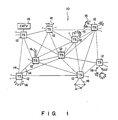
- an optical information communications network system in accordance with one preferred embodiment of the present invention is generally designated by reference numeral "10.”
- This system is called the “broadband integrated digital network for optical data communications” or “B-ISDN system” in short.
- Optical data transmission/communications system 10 works under the broadband integrated services digital network (B-ISDN) architecture, and includes a number of terminal stations or local stations 12 as shown in Figure 1. These terminal stations 12 are interconnected directly or indirectly with one another via optical multiplexed signal transmission lines 14 made of optical fiber cables, generally known as the "optical fiber links.” Terminal stations 12 are provided with sub-network systems for data transmission/communications that are associated therewith, respectively. Each of these sub-networks 16 may be any type of network system, such as a local area network, a CATV network, local area network with sub-loop, a simple star-type subscriber communications network, a satellite communications system, and so on. In the following description, sub-networks 16 also follow optical data transmission systems; electrical data transmission systems may be used instead to these networks 16.
- B-ISDN broadband integrated services digital network
- Each of terminal stations 12 takes in and sends out several kinds of optical information signals so that communication can be made between itself and one or a plurality of terminal stations 12 associated in this B-ISDN system.
- the transmission of optical input signals and output signals of each terminal station 12i is transmitted via the corresponding ones of optical fiber link cables 14.
- Each terminal station 12 extracts, from the input information signals externally supplied thereto, some information signals which are to be transferred to sub-network 16i associated with the terminal station 12i; each station 12i handles and exchanges the remaining information signals, e.g., the signals to be distributed to other terminal station or stations via itself, in accordance with the destination data of the information signals.
- each terminal station 12 is equipped with an internal digital data switching unit, which will be explained in detailed later in this specification.
- Optical data transmission/communications system 10 deals with optical information signals which are multiplexed based on the B-ISDN architecture. These information signals are multiplexed in such a manner that the signals aiming at the same destination area (or terminal station) are time-division multiplexed together to produce time-division multiplexed information signal cells, and that specific signals of these signals to be transferred to the same direction (link) are "bundled together by "optical frequency-division multiplex processing.
- the resultant multiplexed signals may include several kinds of information or data signals such as high-definition TV image signals, computer data signals, audio signals, etc.
- each information signal is digitized, time-division multiplexed, and then optical frequency-division multiplexed to thereby produce time-division/optical frequency-division information signals which are assigned with a preselected optical frequency, respectively.
- a group of information signals of 150 Mbps are 16-channel time-division multiplexed for the purpose of data transmission, and then converted into a digital multiplexed signal having a series of cells the data rate of which is 2.5 Gbps. Each cell is 125 microseconds in length.
- Each of the digital multiplexed signals are "superimposed" with a carrier light having a predetermined optical baseband frequency on the corresponding optical fiber link cable 14.
- CPFSK Continuous phase frequency shift-keying
- a specific scheme is utilized wherein, if the sum of empty channels remaining in two adjacent cells which deal with data signals to be directed to the same direction exceeds the total channel number (16, for example) of a cell, these two cells are combined together to define a new enlarged cell.
- the cell usage efficiency in the branch-line exchange system can be improved to be as high as that in the packet exchange system.
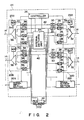
- one terminal station 12i essentially consists of four parts: an array of signal receiver (input) sections 20a, 20b,..., 20n; an array of signal transmitter (output) sections 22a, 22b,..., 22n; digital data switching (data exchange) unit 24; and main controller 26.
- Internal switching unit 24 is generally provided between signal input sections 20 and signal output sections 22, and co-operates not only signal input sections 20 and signal output sections 22, but also with sub-loop 16i which associates with terminal station 12i.
- Main controller 26 is provided so that it communicates directly with the internal components 20, 22, and 24.
- Main controller 26 may be a digital computer that controls individually or wholly these components.
- Signal input sections 20 are connected with the corresponding ones of optical fiber cables 12 respectively, and receives optical digital CPDSK-multiplexed data signals that are externally transmitted and supplied to this terminal station 12i.
- Internal switching unit 24 internally exchanges some of electrical data signals generated by signal input sections 20, or the all of the data signals, if desired, and distributes these signals among signal output sections 22 under the control of main controller 26.
- Signal output sections 22 are connected with the corresponding ones of optical fiber cables 12 respectively, and send out or transmit optical CPFSK-multiplexed data signals externally.
- Each of signal output sections 22 includes a plurality of electrooptical converting devices 28, which may be called the "E/O converters.” Some of these receivers 28 are associated with signal input sections 20a, 20b,..., 20n via internal switching unit 24; others of them are connected in direct with the signal input sections by direct connection line units 30, i.e., they are connected with the signal input sections without through switching unit 24. E/O converters 28 may operate independently of one another. In each signal output section 22, all of devices 28 provided therein are connected at their output terminals to optical demultiplexer 32. Optical demultiplexer 32 is supplied with optical network control signals Snc that are supplied from main controller 26 via network control signal transmitting devices 34.
- Every O/E conversion device 28 is constituted by using a laser drive circuit, a data buffer memory, a wavelength-tunable semiconductor laser module with optical isolators, a laser wavelength stabilizer circuit, a laser output intensity stabilizer circuit, and the like, which are not shown in the accompanying drawings, and superimpose digital data signals with carrier light to produce optical digital CPFSK data signals to be transmitted externally out of terminal station 12i.
- the range of laser oscillation wavelength may be about a 1.55 micrometers band.
- the width of laser oscillation spectrum may be 4 MHz; the wavelength tuning range may be 800 GHz (wavelength is about 6.4 nanometers) or more.
- the channel width is set to 12.5 GHz (wavelength is 0.1 nanometer)
- 65 channel-data transmission may be available in maximum by using 65 devices 28 in each signal output section 22 of terminal station 12i.
- one channel is assigned to network control signal transmitter 34; therefore, 64 data signal transmission channels are provided in each signal output section 22.
- main controller 26 searches for a "free" optical frequency channel that remains unoccupied, and sets the optical frequency of device 28 to that of the free optical frequency channel. The length of such frequency switching time will be determined depending upon the carrier life-time inside the semiconductor laser being used (not shown in Fig.
- high-speed frequency switching of less than 10 nanometers may be available for device 28 if suitable circuit design is made.
- the maximum number of data signal reception devices 28 to be connected to an optical fiber link cable 14 is larger than the number of optical frequency channels.
- Network control signal transmitter 34 "bundles” or assembles together rough destination data of the time-division multiplexed data signal cells using a specifically selected frequency that is out of the frequency band assigned to these data signal cells; a plural pieces of the destination data bundled are supplied to optical multiplexer 32 prior to the transfer to these data cells.
- the optical frequency of oscillation of network control signal transmitter 34 is fixed to a predetermined value.
- the other conditions may be same as those used in E/O converters 28 described above.
- Network control signal Snc may include in addition to the destination data a monitor signal which indicates degradation in data transmission, such as fault, malfunction, busy, etc. if any, a synchronization signal, or the like.
- the synchronization signal is used to synchronize the operations of overall components in each of signal output sections 22.
- Optical multiplexer 32 execute an optical frequency-division multiplexing processing with respect to optical output signals of data signal reception devices 28 and those of network control signal transmitter 34, e.g., optical network control signal, thereby generating an optical data signal that is optical frequency-multiplexed. This optical signal is then supplied to the corresponding optical fiber link cable 14 out of terminal station 12i.
- optical multiplexer 32 has a plurality stages of optical fiber coupler units (now shown in Fig. 2), each of which is made of a matrix of single-mode optical fiber couplers of 2 rows and 2 columns.
- the number of the stages of optical fiber coupler units will increase as the optical signals to be subjected to the optical multiplexing process are increased in number.
- An optical amplifier may be added if such increase in the stage number of optical fiber coupler units causes the coupling loss to increase beyond an allowable upper limitation.
- the time-division/optical frequency-division multiplexed data signals that are generated in the manner as described above will be then transferred by optical fiber link cables 14 to a target terminal station or stations 12.
- Terminal station 12i shown in Figure 2 is also supplied with time-division/optical frequency-division multiplexed data signals from other associating terminal stations not shown in Figure 2 in the same manner of data transmission.
- These optical input multiplexed data signals enter first to signal input sections 20a, 20b,..., 20n of terminal station 12i shown in Figure 2.
- each of signal input sections 20 includes optical demultiplexer 36 which is connected to the corresponding one of optical fiber link cables 14.
- Optical demultiplexer 36 "disassembles" or demultiplexes optical multiplexed data signals into several number of individual time-division multiplexed data signals having different optical frequencies and a network control signal Snc containing rough destination data signals assigned thereto.
- the demultiplexed signals are still optical signals.
- the internal function of optical demultiplexer 36 is in principle reverse to that of the aforementioned optical multiplexer 32.
- the signal loss in optical demultiplexer 36 may be compensated for by an optical amplifier that will be additionally provided in the signal input sections 20, if required.
- Demultiplexed output signals of optical demultiplexer 36 are supplied to an array of optoelectric (O/E) converting devices 38.
- O/E data converters 38 is a wavelength-selective data reception device, which can detect or sense only a specific optical signal component having a predetermined optical frequency.
- Data receiving devices may be polarization diversity reception type heterodyne delay detectors, which use as their local oscillation light source a wavelength-changeable semiconductor laser element.
- the width of local oscillation spectrum is 4 MHz; the wavelength tuning range is 800 GHz or more.
- the intermediate frequency band of it is about 5 GHz.
- the number of O/E converters 38 to be provided in each signal input section is so set as to be larger than the optical frequency channel of optical fiber link 14.
- the tuning of optical frequency is performed with each data cell as a unit.
- optical demultiplexer 36 is also connected with network control signal reception device 40, which detects only an optical signal component of a specifically selected optical frequency, including a network control signal.
- Reception device 40 is essentially same in its configuration as devices 38.
- Network control signal Snc′ extracted from the input signals is supplied under the control of main controller 26 to network control signal reception device 40 before several kinds of time-division multiplexed data signals arrive at the corresponding data signal transmitters 38.
- Main controller 26 sets the detectable optical frequencies of O/E converters 38 to the corresponding ones of signal cell wavelengths respectively, that are different from one another, in accordance with the destination data (distribution information) represented by control signal Snc′ so that in each signal input section 20 each of different data signals of mutually different optical frequencies will be transferred to the corresponding device 38.
- main controller 26 In order for main controller 26 to complete the whole setting of optical frequency onto data converting devices 38 before data signals are actually arrive at devices 38, it should be required that the difference between the arrival times of the network control signal Snc′ and the signal cells is larger than the total value of a delay time in network control signal receiver 40, an actual processing time of main controller 26, and an actual setting time of optical frequency in devices 38.
- network control signal Snc′ itself consists of the similar unit cells as in the input data signals, it becomes possible to arrange the signal Snc′ so that it contains at its first half period the distribution information of a next set of data signal cells that will be supplied to the same input section 20 at the next timing which follows just after the instant time in progress, and contains in the second half period several types of control signals such as a signal transmission monitoring signal, a synchronous signal, and the like.
- some suitable degree of time margin can be fixed between the transmission of the data signal cells and the transmission of its distribution information.
- Such time margin will be an extra time that corresponds to a half the cycle of a unit cell time.
- Internal data switching unit 24 disassembles some of time-division multiplexed data cells, which are output by signal input sections 20 and required to at least partially branched to a plurality of optical links or to be transferred or distributed to sub-network 16 associated with this terminal station 12, into a plurality of low-bit rate signals. These low-bit rate signals are then rearranged in such a manner that data signal components to be distributed to the same target terminal station and terminal stations near that station are grouped together, time-division multiplexed again, and optically multiplexed using the same optical frequency carrier.
- the internal data exchange processing of switching unit 24 is also applied to data signals transmitted from sub-network system 16 associated in direct with respective terminal station 12i.
- switching unit 24 does not automatically execute the aforementioned "data signal exchanging rearrangement" operations with respect to all of the time-division multiplexed output data signals of signal input sections 20 in terminal station 12i.
- Data switching unit 24 is released from duty of handing certain data signals which are included in the time-division/optical frequency-division multiplexed input data signals and which simply pass through terminal station 12i in such a form as they are originally input thereto in order to arrive at their desired other target terminal stations; such certain signals are transferred to signal output sections 22 along a separate route via direct connection line path units 30, after leaving O/E data converters 38 of signal input sections 20.
- This route may be called the "direct-transfer line path."
- the above certain data signals simply passing through terminal station 12i are assigned with certain optical frequencies appointed by the network control signal; accordingly, they appear on specific internal data transmission lines 42 only.
- Data switching unit 24 carries out the demultiplexing and exchanging operations only for data signals to be distributed to sub-network system 16i, data signals containing data components to be branched to different optical output fiber cables 14 of terminal station 12i, and data signals supplied from sub-network system 16i; therefore, the processing workload of internal switching unit 24 can be much decreased to lighten its exchanging duty.
- internal switching unit 24 first disassembles data signals input thereto into signals of 155 Mbps. These signals are then subjected to the aforementioned data exchange-processing, whereby the sixteen channels in maximum of signals of same transfer direction are bundled together and time-division multiplexed into 2.5 Gbps data cells.
- a batcher network may be used to collect the data signals to be transferred in same transmission direction in the present "B-ISDN" communications system 10.
- direct connection line units 30 After the completion of internal signal processings, direct connection line units 30 carries out an inverse serial-to-parallel conversion, e.g., parallel-to-serial conversion, so that 2.5 Gbps signals are obtained again. The signals are then supplied to the corresponding ones of signal output sections 22. It should be noted that the timing adjustment and the waveform-shaping processing can be performed successfully without degrading the data transmission rate if high-speed ICs are used. In this case, serial-to-parallel conversion for converting 2.5 Gbps signals to low-rate signals will no longer be required; the above-mentioned internal signal adjustment processings can be effectively performed by using only a buffer memory for storing data temporarily.
- an inverse serial-to-parallel conversion e.g., parallel-to-serial conversion
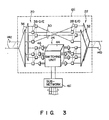
- a model illustration shown in Figure 3 is provided in order to make it easy to understand the essence of the complicate internal arrangement of terminal station 12i.
- a number of optical demultiplexers 36 of signal input sections 20 are respectively connected to data inputting optical fiber cables 14a; a number of optical multiplexers 32 of signal output sections 22 are respectively connected to data outputting optical fiber cables 14b.
- Optical output data signals of optical demultiplexers 36 are converted by the corresponding optoelectric converters 38 into electrical data signals.
- the rest of electrical data signals e.g., data signals which enter terminal station 12i to simply pass through it in order to finally arrive at their target terminal stations other than station 12i in a signal form as they are input to terminal station 12i, are specifically arranged: they are directly sent to multiplexers 32 of signal output sections 22 without via switching unit 24.
- Signal output sections 22 have E/O data converting devices 28 serving as electrooptical converters, by which the data signals before they converter into the corresponding optical signals before they are supplied to optical multiplexers 32.
- Internal switching unit 24 may be constituted by main switch section 44 that handles electrical data signals, demultiplexers 46 provided at the pre-stage of main section 44, and multiplexers 48 provided at the post-stage of the main section.
- Main section 44 is connected to subnetwork 16i such as a LAN system, which is associated with terminal station 12i.
- Electrical output signals of main section 44 are time-division multiplexed by multiplexers 48 for the purpose of the aforementioned date "rearrangement and exchange" processing, converted by electroopitcal converters 28 into electrical data signals, and then sent out by optical multiplexers 32 onto either data outputting optical fiber cables 14b or subnetwork system 16i.
- switching unit 24 which is provided inside each of associating terminal stations 12 is B-ISDN type optical data communications network system 10 can be released from duty of handing the entire part of time-division multiplexed data signals that are supplied and input to terminals station 12i including the data switching unit in accordance with the optical frequency-multiplex scheme.
- Internal switching unit 24 may execute its data exchange with respect only to the minimum number (20 percent of the total input data signals) of input data signals selected to meet the above-mentioned conditions; the remaining ones of the input data signals are "processed" by direct connection line units 30 without via switching unit 24. This arrangement enables to decrease or lighten the workload of internal switching unit 24 in each terminal station 12i.
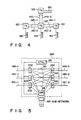
- B-ISDN type optical data communications network system 10 in accordance with one preferred embodiment of the present invention will be described in more detail with reference to a model of simplified network system presented in Figures 4 and 5.
- four terminal stations 12a, 12b, 12c, and 12d exit and are associated with one another via data inputting optical fiber cables 14a-1, 14b-1, 14c-1 and data outputting optical fiber cables 14a-2, 14b-2, 14c-2.
- Terminal stations 12a, 12b, 12c, 12d are provided with subnetwork systems 16a, 16b, 16c, 16d, respectively.
- One of these terminal stations 12a, 12b, 12c, 12d, station 12d for example, has its internal circuit configuration shown in Figure 5.
- the internal arrangement of a certain input section 20a of terminal station 12d is shown in Figure 6.
- input section 20a of terminal station 12d has an array of optoelectric converters which serve as network control signal receiver 40 and O/E data converters 38.
- These optoelectric converters are allocated with detectable optical frequencies ⁇ under the control of main controller 26.
- optical frequency ⁇ 0 is assigned to the optoelectric converter acting as network control signal receiver 40; the remaining optoelectric converters 38-1, 38-2,..., 38-8 are assigned with optical frequencies ⁇ 1, ⁇ 2,..., ⁇ 8, respectively.
- Network control signal receiver 40 extracts network control signal Snc′ from the output signals of optical demultiplexer 36, and supplies it to main controller 26 (see Figure 2).
- time-division multiplexed data signals output by data signals of devices 38-1 through 38-6 are transferred to output section 22a; only those of devices 38-7 and 38-8 are supplied to internal switching unit 24.
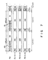
- Data signal transmission channels ⁇ 1, ⁇ 2, and ⁇ 3 have data cells designated by "Dij," wherein suffix "i” designates the channel number, while suffix "j” denotes the order of appearance on the time axis.
- the data transmission rate is 2.5 Gbps.
- Each cell Dij is sixteen-channel time-division multiplexed at 150 Mbps.
- Each cell Dij has flag Fij at its front most position thereof.
- the destination of cell D10 is terminal station 12b, that of cell D20 is stations 12c: cell D30 is "empty.”
- the detectable optical frequency ⁇ 3 of optoelectric converting device 38-3 is set to " ⁇ 1"; that ⁇ 5 of device 38-5 is set to " ⁇ 2.”
- the remaining data receivers are kept insensitive.
- main controller 26 causes device 38-5 to be kept inoperative, and at the same time, changes the sensible optical frequencies ⁇ 4 and ⁇ 7 of devices 38-4 and 38-7 to be equal to " ⁇ 2" and " ⁇ 3," respectively.
- Destination data components H11 and H21 are transferred to network control signal transmitter 34 (see Fig. 2) in signal output section 22b during the second half period of the cell time, and will be sent out onto a corresponding optical fiber cable 14b-2 before data cells having the contents of data cells D11 and D21 are externally transmitted.
- the contents of data cell D31 is disassembled by switching unit 24 into sixteen channel data components. Some of these data components which will be distributed to sub-network 16d are bundled together and supplied to the sub-network. Data signals which aims at terminal station 12b are time-division multiplexed with other data signals, which are supplied from another optical fiber cable, such as cable 14c-1, and/or from sub-network system 16d and will be transferred also to terminal station 12b; so that new data cell is formed. The new data cell is then transferred to signal output section 22b.
- main controller 26 generates, for such new data cell, a new destination data signal, which is supplied to network control signal transmitter 34 (see Figure 2) of output section 22b.
- Data signal cells D11 and D21 that aim at terminal station 12b as their target are prevented from being transferred via switching unit 24: they are directly supplied by direct connection line units 30 to signal output section 22b.
- destination data component H12 of network control signal cell C1 represents that data signals are to be uniformly and simultaneously distributed toward all the terminal stations associated in this communications system in a manner generally known as the "broadcast type data distribution," and wherein destination data component H22 designates terminal station 12b, while destination data component H32 designates terminal stations 12c and 12d.
- data cell D32 is divided by switching unit 24 into a group of data to be transferred to optical fiber cable 14c-2 and a group of data to be transferred to sub-network system 16d.
- Data cell D12 detected by optoelectric converter acting as data signal transmitter device 38-6 is identified by switching unit 24 from the others, and is then transferred sub-network system 16d.
- the contents of cell D12 is transferred also to terminal stations 12b and 12c via O/E converters 38-3 and 38-5 and direct connection line units 30.
- switching unit 24 is supplied with 1,920 branch-line input signals, that is 16 times 12 times 10 at 150 Mbps.
- the internal circuit arrangement of switching unit 24 can be simplified to less than one twenty-fifth that of the conventional one, since it is almost proportional to square value of the input channel number.
- Increasing of input/output sections in its scale may be easily compensated for by utilizing solid-state electronic elements, such as semiconductor lasers, arrays of photodetective devices, ICs, LSIs, etc. Power consumption may be kept small since all of the components constituting the signal input/output sections are not always activated at the same time.
- Technical advantages resulting from simplification of data exchange units will surpass disadvantages that comes after enlargement in the scale of signal input/output sections.
- the network control signal is arranged so that it is optical frequency-division multiplexed at the same rate and under the same conditions as in the data signals; however, the network control signal may be processed in a different modulation/demodulation method and at a different data transmission rate.
- the network control signal may be transmitted in a plurality of fixed optical wavelengths. It is also a possible modification that the network control signal be processed in accordance with a direct-intensity modulated/direct detection scheme at 50 Mbps in 1.3 micrometers bandwidth.
- the destination data signal of the network control signal should not be necessarily provided for all the data cells; in such a case, the network control signal will be supplied only when the connection among data transmission lines is at least partially changed.
- main controller 26 can change the state of some of the data outputting optical fiber link cables to be connected to the destination address represented by the network control signal.
- the network control functions should not be fixedly gathered in a single component such as the "main controller.” This means that the control functions executed by main controller 26 may be scattered among signal input sections 20, signal output sections 22, data exchange unit 24, and the like.
- the control signal for each optical fiber link cable may be processed by a control subsection that is additionally provided inside each of the signal input sections.
- main controller 26 instead performs the total control of control subsections scattered among internal components of the terminal station and/or the processing of the network control signal. It is naturally said that all the optical terminal stations 12 are equivalent in its network control architecture with one another: it may be possible for some of the terminal stations to have a predetermined hierarchical structure such as a network terminal that is to be controlled by a center station for serving as the central network manager.
- each optical fiber link cable is arranged so as to internally operate in synchronism with data cells; however, the system of this invention may also to applied to a non-synchronous data transmission systems.
- data signals having different optical frequencies are made of length-changeable packet signal components each of which is associated with a corresponding control signal that is to be transmitted in a specific optical frequency prior to the transmission of the packet signals.
- main controller 26 selects an "empty" one from among those of optoelectric data converting devices 38 which are connected with the destination designated by the input control signal, and tuning its detectable optical frequency to a suitable optical frequency.
- the embodiment described above may also be modified so that a header data is added independently of the network control signal to either each data signal cell or each packet.
- the internal data exchange of data switching unit 24 may be performed in accordance with a self-routing exchange scheme. New destination data for rearranged multiplexed signals may be produced based on the header data.
- the internal data exchange in each terminal station may also be carried out by using the network control signal.
- the header data will be able to be used as a part of the corresponding data signal: the header will be handled by a sub-network system 16 associated with the terminal station without any modification.
- the present optical fiber data transmission protocol can also deal with 1:N-broadcast type data communication systems wherein a plurality of pieces of destination data are assigned to a certain data signal, since main controller 26 can control optoelectric converters 38 which are respectively coupled with the corresponding one of the plural pieces of destination data to be set to the respective optical frequency of the data signal. This will become very advantageous when it is applied to various types of B-ISDN type data integration/communication systems.
- each of the optoelectric converters 38 is connected either one of direct connection line path 30 connected to a pre-selected, specific data output section 22 and data exchange unit 24; however, it may be modified so that it is selectively connected to one of them under main controller 26, using a software program or a hardware switching means.
- each of electrooptical converters 28 may be modified so as to be selectively connected either data output section 22 or data exchange unit 24 as required statistically.
- the system expansion can be made by simply adding a new branch to those of optical demultiplexers 36 and optical multiplexers 32 which remain unused, without any confliction with the presently executing data processing/communication operations.
- the expansion of system electricity may be accomplished by adding a physical electric circuit board.
- Main controller 26 is itself an independent computer system, so that it may be freely modified by simple extra programming so as to be adapted to system expansion. If the system expansion comes to the limitation with respect to a certain optical frequency band, optical frequency-division multiplexed data signals may be subjected to wavelength-division multiplex processing using a different optical frequency band.
- 256 channels of data signals can be transmitted together on a single line of optical fiber cable, by performing 64-channel optical frequency-division multiplex with respect to 1.50-micrometer band, 1.52-micrometer band, 1.54-micrometer band, and 1.56-micrometer band, respectively. In that case, if 1 channel is set to 2.5 Gbps, 640-Gbps optical data transmission will be available.
- the data transmission system of the above embodiment of this invention may be used as an optical data exchange apparatus if data output sections 22 for receiving input data signal supplied from sub-network system 16 are combined with data input sections 20 the output signals of which are transferred to the sub-network system using short-length optical fiber link cables.
Landscapes
- Engineering & Computer Science (AREA)
- Computer Networks & Wireless Communication (AREA)
- Optical Communication System (AREA)
- Use Of Switch Circuits For Exchanges And Methods Of Control Of Multiplex Exchanges (AREA)
- Interface Circuits In Exchanges (AREA)
- Time-Division Multiplex Systems (AREA)
- Data Exchanges In Wide-Area Networks (AREA)
Applications Claiming Priority (2)
| Application Number | Priority Date | Filing Date | Title |
|---|---|---|---|
| JP1135507A JP2777194B2 (ja) | 1989-05-29 | 1989-05-29 | 光伝送方式 |
| JP135507/89 | 1989-05-29 |
Publications (3)
| Publication Number | Publication Date |
|---|---|
| EP0400959A2 true EP0400959A2 (fr) | 1990-12-05 |
| EP0400959A3 EP0400959A3 (fr) | 1992-04-15 |
| EP0400959B1 EP0400959B1 (fr) | 1995-08-23 |
Family
ID=15153377
Family Applications (1)
| Application Number | Title | Priority Date | Filing Date |
|---|---|---|---|
| EP90305821A Expired - Lifetime EP0400959B1 (fr) | 1989-05-29 | 1990-05-29 | Système de réseau de communication d'information à large bande avec lignes de transmissions de données cohérentes optiques |
Country Status (4)
| Country | Link |
|---|---|
| US (1) | US5077727A (fr) |
| EP (1) | EP0400959B1 (fr) |
| JP (1) | JP2777194B2 (fr) |
| DE (1) | DE69021778T2 (fr) |
Cited By (5)
| Publication number | Priority date | Publication date | Assignee | Title |
|---|---|---|---|---|
| GB2282018A (en) * | 1993-09-14 | 1995-03-22 | Northern Telecom Ltd | Optical communications network |
| GB2291311A (en) * | 1994-07-07 | 1996-01-17 | Plessey Telecomm | Telecommunications optical network |
| US5604734A (en) * | 1994-06-10 | 1997-02-18 | Telefonaktiebolaget Lm Ericsson | ATM-system adapted three stage switching unit |
| WO1999057850A3 (fr) * | 1998-05-06 | 2000-06-02 | Ciena Corp | Systeme de controle de messages d'octets jo sonet |
| EP1231811A3 (fr) * | 2001-02-07 | 2002-09-18 | Redfern Broadband Networks Pty Ltd | Commutateur optique-électrique-optique transparent |
Families Citing this family (28)
| Publication number | Priority date | Publication date | Assignee | Title |
|---|---|---|---|---|
| JP3308525B2 (ja) * | 1990-11-30 | 2002-07-29 | 株式会社日立製作所 | ネットワーク |
| JPH04223757A (ja) * | 1990-12-26 | 1992-08-13 | Toshiba Corp | Isdn端末装置 |
| BE1004813A3 (nl) * | 1991-05-08 | 1993-02-02 | Bell Telephone Mfg | Optische zender/ontvangerinrichting. |
| US5365344A (en) * | 1991-06-27 | 1994-11-15 | Nec Corporation | System for transmitting data using wavelength division multiplexing |
| GB9200897D0 (en) * | 1992-01-16 | 1992-03-11 | British Telecomm | Optical processing in asynchronous transfer mode network |
| EP0637182A3 (fr) * | 1993-07-30 | 1995-11-29 | At & T Corp | Noeud de communication optique à auto acheminement utilisant des portes sagnac. |
| US5550818A (en) * | 1994-09-19 | 1996-08-27 | Bell Communications Research, Inc. | System for wavelength division multiplexing/asynchronous transfer mode switching for network communication |
| JP2888272B2 (ja) * | 1994-12-15 | 1999-05-10 | 日本電気株式会社 | 光ネットワークおよび中継ノード |
| US6950388B2 (en) * | 1996-08-22 | 2005-09-27 | Tellabs Operations, Inc. | Apparatus and method for symbol alignment in a multi-point OFDM/DMT digital communications system |
| US6771590B1 (en) | 1996-08-22 | 2004-08-03 | Tellabs Operations, Inc. | Communication system clock synchronization techniques |
| US6118758A (en) * | 1996-08-22 | 2000-09-12 | Tellabs Operations, Inc. | Multi-point OFDM/DMT digital communications system including remote service unit with improved transmitter architecture |
| US6631018B1 (en) | 1997-08-27 | 2003-10-07 | Nortel Networks Limited | WDM optical network with passive pass-through at each node |
| US6128113A (en) * | 1998-03-04 | 2000-10-03 | Dynamics Research Corporation | Transparent optical communications switch |
| US7440498B2 (en) | 2002-12-17 | 2008-10-21 | Tellabs Operations, Inc. | Time domain equalization for discrete multi-tone systems |
| US6631175B2 (en) | 1998-04-03 | 2003-10-07 | Tellabs Operations, Inc. | Spectrally constrained impulse shortening filter for a discrete multi-tone receiver |
| ES2389626T3 (es) | 1998-04-03 | 2012-10-29 | Tellabs Operations, Inc. | Filtro para acortamiento de respuesta al impulso, con restricciones espectrales adicionales, para transmisión de múltiples portadoras |
| US6567429B1 (en) | 1998-06-02 | 2003-05-20 | Dynamics Research Corporation | Wide area multi-service broadband network |
| US6108331A (en) * | 1998-07-10 | 2000-08-22 | Upstate Systems Tec, Inc. | Single medium wiring scheme for multiple signal distribution in building and access port therefor |
| US6529963B1 (en) | 1998-12-29 | 2003-03-04 | Lsi Logic Corporation | Methods and apparatus for interconnecting independent fibre channel fabrics |
| US6647208B1 (en) * | 1999-03-18 | 2003-11-11 | Massachusetts Institute Of Technology | Hybrid electronic/optical switch system |
| US6529868B1 (en) | 2000-03-28 | 2003-03-04 | Tellabs Operations, Inc. | Communication system noise cancellation power signal calculation techniques |
| WO2002009336A1 (fr) * | 2000-07-05 | 2002-01-31 | Elematics, Inc. | Systeme de commutation optique |
| ATE336053T1 (de) * | 2000-11-24 | 2006-09-15 | Caliel S R L | Verteilungsystem für dateien mit digitalen daten unter verwendung eines rechnernetzwerks |
| EP1271825A1 (fr) * | 2001-06-25 | 2003-01-02 | Lucent Technologies Inc. | Procédé et système pour le transport d'information optique multiplexé |
| JP2003087205A (ja) * | 2001-09-13 | 2003-03-20 | Hitachi Ltd | 光伝送システム |
| JP4939981B2 (ja) * | 2007-03-06 | 2012-05-30 | 株式会社イセキ開発工機 | 地中管取替え装置 |
| US20090247006A1 (en) * | 2008-01-22 | 2009-10-01 | Wi3, Inc., New York | Network access point having interchangeable cartridges |
| US9398354B2 (en) * | 2013-02-20 | 2016-07-19 | Xtera Communications, Inc. | Integrated assembly for switching optical signals |
Family Cites Families (8)
| Publication number | Priority date | Publication date | Assignee | Title |
|---|---|---|---|---|
| DE2951495A1 (de) * | 1979-12-20 | 1981-07-02 | Siemens AG, 1000 Berlin und 8000 München | Breitband-fernmeldesystem |
| JPS58164340A (ja) * | 1982-03-24 | 1983-09-29 | Toshiba Corp | 光デ−タウエイシステム |
| JPS59158661A (ja) * | 1983-03-01 | 1984-09-08 | Nec Corp | 光交換器 |
| EP0166595B1 (fr) * | 1984-06-25 | 1992-04-08 | Kabushiki Kaisha Toshiba | Système de communication d'informations |
| US4821255A (en) * | 1987-05-06 | 1989-04-11 | Bell Communications Research, Inc. | Cross-connection of wavelength-division-multiplexed high speed optical channels |
| JPS63294144A (ja) * | 1987-05-27 | 1988-11-30 | Matsushita Electric Ind Co Ltd | Catv網における端末間通信方式 |
| DE3853935T2 (de) * | 1987-09-30 | 1995-10-12 | Nippon Electric Co | Zeit- und Wellenlängenmultiplex-Vermittlungssystem. |
| US4928272A (en) * | 1988-05-23 | 1990-05-22 | Matsushita Electric Industrial Co., Ltd. | Two-way CATV system using frequency division multiplexing |
-
1989
- 1989-05-29 JP JP1135507A patent/JP2777194B2/ja not_active Expired - Lifetime
-
1990
- 1990-05-29 DE DE69021778T patent/DE69021778T2/de not_active Expired - Lifetime
- 1990-05-29 US US07/530,156 patent/US5077727A/en not_active Expired - Lifetime
- 1990-05-29 EP EP90305821A patent/EP0400959B1/fr not_active Expired - Lifetime
Cited By (10)
| Publication number | Priority date | Publication date | Assignee | Title |
|---|---|---|---|---|
| GB2282018A (en) * | 1993-09-14 | 1995-03-22 | Northern Telecom Ltd | Optical communications network |
| GB2282018B (en) * | 1993-09-14 | 1998-03-18 | Northern Telecom Ltd | Optical communications network |
| US5604734A (en) * | 1994-06-10 | 1997-02-18 | Telefonaktiebolaget Lm Ericsson | ATM-system adapted three stage switching unit |
| GB2291311A (en) * | 1994-07-07 | 1996-01-17 | Plessey Telecomm | Telecommunications optical network |
| GB2291311B (en) * | 1994-07-07 | 1999-04-07 | Plessey Telecomm | Telecommunications network |
| US6097736A (en) * | 1994-07-07 | 2000-08-01 | Marconi Communications Limited | Telecommunications network |
| WO1999057850A3 (fr) * | 1998-05-06 | 2000-06-02 | Ciena Corp | Systeme de controle de messages d'octets jo sonet |
| US6278535B1 (en) | 1998-05-06 | 2001-08-21 | Ciena Corporation | SONET Jo byte message monitoring system |
| EP1641159A1 (fr) * | 1998-05-06 | 2006-03-29 | Ciena Corporation | Système de contrôle de messages d'octets J0 SONET |
| EP1231811A3 (fr) * | 2001-02-07 | 2002-09-18 | Redfern Broadband Networks Pty Ltd | Commutateur optique-électrique-optique transparent |
Also Published As
| Publication number | Publication date |
|---|---|
| JPH031626A (ja) | 1991-01-08 |
| EP0400959B1 (fr) | 1995-08-23 |
| DE69021778D1 (de) | 1995-09-28 |
| EP0400959A3 (fr) | 1992-04-15 |
| DE69021778T2 (de) | 1996-01-11 |
| JP2777194B2 (ja) | 1998-07-16 |
| US5077727A (en) | 1991-12-31 |
Similar Documents
| Publication | Publication Date | Title |
|---|---|---|
| EP0400959A2 (fr) | Système de réseau de communication d'information à large bande avec lignes de transmissions de données cohérentes optiques | |
| CA1290474C (fr) | Interconnexion de canaux rapides a multiplexage optique | |
| US5550818A (en) | System for wavelength division multiplexing/asynchronous transfer mode switching for network communication | |
| EP0382431B1 (fr) | Réseau de communication | |
| CN109560891B (zh) | 实现波分复用光信号分路的方法及装置 | |
| CN100499435C (zh) | 用于突发数据通信的光多环网 | |
| EP1162860A3 (fr) | Architecture à échelle variable, d' un routeur IP optique WDM | |
| Stern | Linear lightwave networks: How far can they go? | |
| JP2001016625A (ja) | 光クロスコネクト装置および光ネットワーク | |
| JPH11252126A (ja) | 大容量波長分割多重化光atmスイッチ | |
| CN115278403A (zh) | 电交换集群系统 | |
| EP1473962B1 (fr) | Système et procédé de communication WDM avec entrelacement des signaux optiques pour une utilisation efficace de la longueur d'onde | |
| JP3574754B2 (ja) | 光パスクロスコネクト装置 | |
| US7010226B2 (en) | Packet router for use in optical transmission networks | |
| CN100584101C (zh) | 光交换站和用于该交换站的交换方法 | |
| JP4598934B2 (ja) | 光伝送装置および光伝送システム | |
| US20050129403A1 (en) | Method and system for communicating optical traffic at a node | |
| Kannan et al. | STWnet: A high bandwidth space-time-wavelength multiplexed optical switching network | |
| CN1946013B (zh) | 业务信号节点交叉调度方法和系统 | |
| JP3334967B2 (ja) | コンセントレータ及びこれを用いた光通信ネットワーク | |
| JP3732771B2 (ja) | 光パケットルーティングシステムおよび光パケットルーティング方法 | |
| Papadimitriou et al. | Wavelength-conversion-based protocols for single-hop photonic networks with bursty traffic | |
| KR100281419B1 (ko) | 완전광 패킷 스위칭 시스템 | |
| JP2967766B2 (ja) | 光通信ネットワークノード | |
| JP2002064547A (ja) | スイッチ装置及びスイッチング方法 |
Legal Events
| Date | Code | Title | Description |
|---|---|---|---|
| PUAI | Public reference made under article 153(3) epc to a published international application that has entered the european phase |
Free format text: ORIGINAL CODE: 0009012 |
|
| 17P | Request for examination filed |
Effective date: 19900611 |
|
| AK | Designated contracting states |
Kind code of ref document: A2 Designated state(s): DE FR GB |
|
| PUAL | Search report despatched |
Free format text: ORIGINAL CODE: 0009013 |
|
| AK | Designated contracting states |
Kind code of ref document: A3 Designated state(s): DE FR GB |
|
| 17Q | First examination report despatched |
Effective date: 19940121 |
|
| GRAA | (expected) grant |
Free format text: ORIGINAL CODE: 0009210 |
|
| AK | Designated contracting states |
Kind code of ref document: B1 Designated state(s): DE FR |
|
| REF | Corresponds to: |
Ref document number: 69021778 Country of ref document: DE Date of ref document: 19950928 |
|
| ET | Fr: translation filed | ||
| PLBE | No opposition filed within time limit |
Free format text: ORIGINAL CODE: 0009261 |
|
| STAA | Information on the status of an ep patent application or granted ep patent |
Free format text: STATUS: NO OPPOSITION FILED WITHIN TIME LIMIT |
|
| 26N | No opposition filed | ||
| REG | Reference to a national code |
Ref country code: FR Ref legal event code: D6 |
|
| REG | Reference to a national code |
Ref country code: FR Ref legal event code: ST Effective date: 20090119 |
|
| PG25 | Lapsed in a contracting state [announced via postgrant information from national office to epo] |
Ref country code: FR Free format text: LAPSE BECAUSE OF NON-PAYMENT OF DUE FEES Effective date: 20080602 |
|
| REG | Reference to a national code |
Ref country code: FR Ref legal event code: D3 |
|
| PGFP | Annual fee paid to national office [announced via postgrant information from national office to epo] |
Ref country code: DE Payment date: 20090527 Year of fee payment: 20 |
|
| REG | Reference to a national code |
Ref country code: FR Ref legal event code: ST Effective date: 20100129 |
|
| PGFP | Annual fee paid to national office [announced via postgrant information from national office to epo] |
Ref country code: FR Payment date: 20100826 Year of fee payment: 20 |
|
| REG | Reference to a national code |
Ref country code: FR Ref legal event code: D3 |
|
| PGRI | Patent reinstated in contracting state [announced from national office to epo] |
Ref country code: FR Effective date: 20101103 |
|
| PG25 | Lapsed in a contracting state [announced via postgrant information from national office to epo] |
Ref country code: DE Free format text: LAPSE BECAUSE OF EXPIRATION OF PROTECTION Effective date: 20100529 |