EP0400960B1 - Verfahren und Vorrichtung zur Erfassung eines Kraftfahrzeugaufpralls - Google Patents
Verfahren und Vorrichtung zur Erfassung eines Kraftfahrzeugaufpralls Download PDFInfo
- Publication number
- EP0400960B1 EP0400960B1 EP90305822A EP90305822A EP0400960B1 EP 0400960 B1 EP0400960 B1 EP 0400960B1 EP 90305822 A EP90305822 A EP 90305822A EP 90305822 A EP90305822 A EP 90305822A EP 0400960 B1 EP0400960 B1 EP 0400960B1
- Authority
- EP
- European Patent Office
- Prior art keywords
- value
- signal
- output
- deceleration
- accelerometer
- Prior art date
- Legal status (The legal status is an assumption and is not a legal conclusion. Google has not performed a legal analysis and makes no representation as to the accuracy of the status listed.)
- Expired - Lifetime
Links
- 238000000034 method Methods 0.000 title claims description 13
- 230000007423 decrease Effects 0.000 claims description 7
- 238000012544 monitoring process Methods 0.000 claims description 5
- 230000000717 retained effect Effects 0.000 claims description 2
- 238000010304 firing Methods 0.000 description 8
- 230000006870 function Effects 0.000 description 7
- 238000010586 diagram Methods 0.000 description 6
- 230000000694 effects Effects 0.000 description 5
- 239000003990 capacitor Substances 0.000 description 4
- 238000006243 chemical reaction Methods 0.000 description 4
- 238000011156 evaluation Methods 0.000 description 4
- 230000004044 response Effects 0.000 description 4
- 230000000630 rising effect Effects 0.000 description 4
- 230000008859 change Effects 0.000 description 3
- 230000001960 triggered effect Effects 0.000 description 3
- 230000004075 alteration Effects 0.000 description 2
- 238000013461 design Methods 0.000 description 2
- 238000012986 modification Methods 0.000 description 2
- 230000004048 modification Effects 0.000 description 2
- 230000008569 process Effects 0.000 description 2
- 230000035484 reaction time Effects 0.000 description 2
- 230000001133 acceleration Effects 0.000 description 1
- 238000004891 communication Methods 0.000 description 1
- 230000001419 dependent effect Effects 0.000 description 1
- 238000005516 engineering process Methods 0.000 description 1
- 230000005484 gravity Effects 0.000 description 1
- 238000012545 processing Methods 0.000 description 1
- 230000006403 short-term memory Effects 0.000 description 1
Images


Classifications
-
- B—PERFORMING OPERATIONS; TRANSPORTING
- B60—VEHICLES IN GENERAL
- B60R—VEHICLES, VEHICLE FITTINGS, OR VEHICLE PARTS, NOT OTHERWISE PROVIDED FOR
- B60R21/00—Arrangements or fittings on vehicles for protecting or preventing injuries to occupants or pedestrians in case of accidents or other traffic risks
- B60R21/01—Electrical circuits for triggering passive safety arrangements, e.g. airbags, safety belt tighteners, in case of vehicle accidents or impending vehicle accidents
- B60R21/013—Electrical circuits for triggering passive safety arrangements, e.g. airbags, safety belt tighteners, in case of vehicle accidents or impending vehicle accidents including means for detecting collisions, impending collisions or roll-over
- B60R21/0132—Electrical circuits for triggering passive safety arrangements, e.g. airbags, safety belt tighteners, in case of vehicle accidents or impending vehicle accidents including means for detecting collisions, impending collisions or roll-over responsive to vehicle motion parameters, e.g. to vehicle longitudinal or transversal deceleration or speed value
Definitions
- the present invention is directed to an actuatable passenger restraint system for a vehicle and is particularly directed to a method and apparatus for sensing deceleration of the vehicle and for providing a signal upon such occurrence to actuate a passenger restraint air bag.
- Actuatable passenger restraint systems for vehicles are well known in the art. Such systems include an inflatable air bag mounted within the passenger compartment of the vehicle. Each air bag in the vehicle has an associated, electrically actuatable ignitor, referred to as a squib. Such systems further include an inertia sensing device for measuring the deceleration of the vehicle. When the inertia sensing device indicates that the vehicle is decelerating a certain amount, an electric current of sufficient magnitude and duration is passed through the squib to ignite the squib which results in inflation of the air bag.
- Such devices are mechanical in nature. Such devices are typically mounted to the vehicle frame and include a pair of mechanically actuatable switch contacts and a resiliently biased weight.
- the weight is arranged such that when the vehicle is decelerated, the weight physically moves relative to its mounting. The greater the deceleration, the more the weight moves against the bias force.
- the switch contacts are mounted relative to the biased weight such that, when the weight moves a predetermined distance, the weight moves over the switch contacts causing them to close. The switch contacts, when closed, connect a squib to a source of electrical energy sufficient to ignite the squib.
- Still other known actuatable passenger restraint systems for vehicles include an electrical transducer or accelerometer for sensing vehicle deceleration. Such systems include a monitoring or evaluation circuit connected to the output of the transducer. The monitoring circuit, upon determining the signal from the transducer indicates a probable crash is occurring, actuates an electrical switch so as to connect electrical energy to the squib.
- US Patent No. 3,870,894 to Brede, et al., (“the ′894 patent”) discloses such an actuatable passenger restraint system.
- the ′894 patent teaches a system which includes an accelerometer, an evaluation circuit connected to the accelerometer, and an ignition circuit or squib connected to an output of the evaluation circuit.
- the accelerometer includes a piezoelectric transducer that provides an electrical output signal having a value indicative of the vehicle deceleration.
- the evaluation circuit includes an integrator electrically coupled to the output of the accelerometer through an amplifier. The output of the integrator is an electrical signal having a value which is functionally related to the integral of the deceleration signal. When the output of the integrator reaches a predetermined value, the ignition circuit of the air bag is fired.
- the integrator used in the ′894 patent is a common resistor/capacitor configuration known in the art.
- the output of the integrator ramps up from electrical ground toward the supply voltage at a rate that is functionally related to the value of the input signal.
- a trigger circuit is connected to the output of the integrator. When the output of the integrator reaches a predetermined value, the trigger circuit actuates a time delay circuit. The time delay circuit begins to time out a predetermined time period. After the time period is timed out, the air bag ignitor is energized.
- the integrator in the ′894 patent in combination with the trigger circuit, provides an indication of the change in velocity of the vehicle.
- U.S patent 3,851,305 describes a system in which a passenger restraint system is actuated when a deceleration value exceeds a certain level.
- the deceleration values generated in US patent 3,851,305 have magnitudes proportional to the decelerations they represent and the reference deceleration value is determined from a further vehicle sensor - a collision detector.
- the present invention provides a new and improved method and apparatus for electrically controlling an actuable passenger restraint system which inflates the system's air bag only upon the occurrence of a crash of sufficient magnitude that requires the use of the air bag for protection of the passengers in the vehicle.
- the present invention provides an apparatus for controlling actuation of a vehicle air bag restraint system, said apparatus comprising: accelerometer means for sensing vehicle declaration and for providing an electric signal having a value functionally related to the sensed deceleration; means for comparing a sensed value of deceleration of the vehicle against a predetermined value; and means for actuating the air bag restraint system when said comparing means indicates the sensed value of the vehicle deceleration is greater than the predetermined value; characterized in that: said accelerometer signal has an RMS value functionally related to the sensed deceleration; said apparatus further comprises means for converting said electric signal provided by said accelerometer means into an RMS value, said RMS value being indicative of the sensed vehicle deceleration value; and said means for comparing compares the converted RMS value against the predetermined value, said predetermined value being indicative of a predetermined deceleration value.
- the converting means in accordance with a preferred embodiment of this invention, includes first heater means connected to the signal provided by the accelerometer means.
- the first heater means radiates heat with a value functionally related to the RMS value of the electric signal from the accelerometer means.
- the converting means further includes first temperature sensor means having a resistive value that is functionally related to the sensed temperature of the first heater means.
- the first temperature sensor means is connected to a resistive voltage dividing network so as to provide a voltage having a value that varies as a function of the temperature sensed by the first sensing means.
- the voltage value across the first temperature sensor is a value that is functionally related to the RMS value of the signal from the accelerometer means.
- the apparatus in accordance with a further preferred embodiment includes a common-mode rejection means operatively connected to the converting means so as to eliminate common-mode rejection errors from the signal provided by the converter prior to providing the converter signal to the comparing means.
- the common-mode rejection means preferably includes a differential amplifier, a first amplifier connected to the first sensor means and to one input of the differential amplifier and second heater means connected to the output of the differential amplifier for radiating heat with a value functionally related to the value of the electric signal from the differential amplifier.
- the common-mode rejection means also includes a second heat sensor associated with the second heater means and a second amplifier connected to the second heat sensor and to a second input of the differential amplifier.
- the second heat sensor has a resistive value that is functionally related to the amount of heat provided by the second heater means.
- the second heat sensor is also connected to a second voltage dividing network for providing the differential amplifier with a voltage value which is functionally related to the value of the output of the differential amplifier.
- the output of the differential amplifier is functionally related to the RMS value of the signal provided by the accelerometer means without a common-mode error component being present.
- the comparing means of the preferred embodiment includes a variable gain amplifier for controlling the converter loop gain.
- the output of the variable gain amplifier is connected to one input of a comparator.
- a voltage dividing network is connected to the other input of the comparator and provides a voltage value against which the converted RMS value of the output signal of the accelerometer means is compared.
- the actuating means includes one-shot means connected to the output of the comparator for providing a pulse signal of predetermined duration upon the occurrence of an accelerometer signal having an RMS value greater than a predetermined value.
- the actuating means further includes electronic switch means operatively connected between a source of electrical energy and an ignitor of the air bag restraint system and controlled by the output of the comparator so as to provide the ignitor with sufficient electrical energy to actuate the ignitor upon the output of the accelerometer indicating a crash of a predetermined magnitude is occurring.
- the present invention also provides a method of controlling actuation of a vehicle air bag restraint system, said method comprising the steps of:
- an apparatus 20 for controlling actuation of an air bag 22 in an actuatable passenger restraint system of a vehicle.
- the apparatus 20 includes a deceleration transducer circuit 24 that provides an output signal 26 having a value indicative of the deceleration of the vehicle.
- the output 26 of the transducer is connected to an RMS thermal converter 28.
- the RMS thermal converter 28 provides an output signal 30 having an RMS value functionally related to the value of the signal 26.
- the output signal 30 is connected to a common-mode rejection circuit 32.
- the common-mode rejection circuit 32 monitors the output signal 30 from the RMS thermal converter 28 and provides an output signal 34 having a converted RMS value which is functionally related to the value of the output signal 26 of the transducer 24 without variance due to common-mode voltage errors.
- the output 34 is connected to a firing circuit 36.
- the firing circuit 36 controls the gain of the converter circuit, including the RMS thermal converter and the common-mode rejection circuit, and compares the converted RMS value against a predetermined value.
- the predetermined value is indicative of a maximum deceleration value, above which it is necessary to fire or actuate the air bag for protection of the vehicle occupants.
- the firing circuit 36 is connected to a squib 38 associated with the air bag 22.
- the squib 38 is connected to a source of electrical energy so as to provide the squib with a predetermined minimum electrical current for a predetermined minimum time period so as to insure proper operation of the squib.
- the deceleration transducer circuit 24 includes a mass 40 suspended by a cantilever support arrangement (not shown).
- Four variable resistors 42 such as piezo-resistors, are mounted to the cantilever support arrangement.
- the resistors 40 are electrically connected in a Wheatstone bridge configuration.
- the mass 40 of the accelerometer moves relative to its mounting, as would occur when the vehicle suddenly decelerates, the resistances of the resistors 42 change and thereby provide an indication of the value of the vehicle deceleration.
- Such a transducer or accelerometer is available commercially from ICSensors, 1701 McCarthy Boulevard., Milpitas, California 95035 under Model No. 3021.
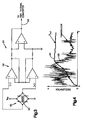
- FIG. 4 shows a graph of the transducer output signal 26 during a vehicle deceleration. The rough appearance to the graph of the output signal 26 is due to the vibrations of the mass 40 during the vehicle deceleration.
- the output signal 26 is connected to the RMS thermal converter 28, as shown in Figure 2.
- the RMS thermal converter 28 includes a heater element 50 connected to the output signal 26 of the transducer 24 and to electrical ground.
- the heater element 50 which may be a resistor, provides heat when electrical current is passed through it.
- the temperature of the heater element 50 is functionally related to the RMS value of the output signal 26.
- a straight forward way to convert the value of the signal 26 into an RMS value is to measure the temperature of the heater element 50. Such a process is known in the art as thermal RMS conversion.
- the converter 28 further includes a temperature sensor 52 associated with and in thermal communication with the heater element 50.
- the sensor 52 has a resistance value that varies as a function of its temperature. Therefore, as the temperature of the heater element 50 varies, the resistance value of the sensor 52 varies.
- the sensor 52 is connected to electrical ground and to a resistor balance circuit 54 which includes a resistor 56 connected to a reference voltage Vcc through a potentiometer 58.
- the junction between resistor 56 and sensor 52 is connected to one input 60 of a differential amplifier 62 through an amplifier 64.
- the output 34 of the differential amplifier 62 is connected to a thermal heater/sensor arrangement 66 through a series resistor 67.
- the heater/sensor arrangement is preferably identical in structure and operation as the RMS thermal converter 28.
- the output 34 of the differential amplifier 62 is connected to a heater element 68 through the series resistor 67.
- the heater element 68 is also connected to electrical ground.
- a sensor 70 associated with and thermally coupled to the heater element 68, is connected to electrical ground and to the reference voltage Vcc through a resistor 72 and potentiometer 58.
- the junction of resistor 72 and sensor 70 is operatively connected to a second input 74 of differential amplifier 62 through an amplifier 76.
- the amplifiers 64, 76 form an instrumentation amplifier 78 that amplifies the voltage difference present across sensor 52 and sensor 70.
- the differential amplifier 62 includes an operational amplifier (“op amp") 80 having a non-inverting input 60 and an inverting input 74.
- the output of amplifier 64 is connected to the non-inverting input 60.
- the output of amplifier 76 is connected to the inverting input 74.
- a capacitor 82 and a resistor 84 are connected between the non-inverting input 60 of the op amp 80 and electrical ground so as to provide a low pass filter.
- the output 86 of the op amp 80 is connected to the base of a NPN transistor 88 through a resistor 90.
- the collector of the transistor 88 is connected to a reference voltage Vcc.
- the emitter of transistor 88 is connected to the firing circuit 36 and connected to the heater 68 through the series resistor 67 of the thermal sensor arrangement 66.
- the emitter of transistor 88 is further connected back to the inverting input 74 through the parallel combination of capacitor 92 and resistor 94.
- the capacitor 92 and the resistor 94 function as a low pass filter. This arrangement provides a source of current for the heater 68.
- the output 34 of the differential amplifier 62 is connected to an amplifier 100 of the firing circuit 36, as shown in Figure 2.
- the amplifier 100 includes an operational amplifier 102 having its non-inverting input connected to the output 34 of the differential amplifier 62 through a potentiometer 104.
- the output 106 of the op amp 102 is fed back to its inverting input through a resistor network including resistors 108, 110.
- the amplifier 100 is used to control the loop gain of the RMS thermal converter.
- potentiometer 104 is adjusted so that the gain of the signal processing circuitry, including the RMS thermal converter 28, the common-mode rejection circuit 32, and the amplifier 100, is equal to one.
- the output 106 of the op amp 102 is connected to one input of a comparator 112.
- the other input of the comparator 112 is connected to a predetermined reference voltage 114 which is derived from the reference voltage Vcc through the resistor divider network 116.
- the predetermined reference voltage is established through a resistor dividing network connected between the reference voltage Vcc and electrical ground.
- the network 116 includes resistors 118, 120.
- the output 122 of the comparator 112 is connected to an edge triggered one-shot 124.
- the one-shot can be selected to trigger off the rising edge or the falling edge of the output signal 122. Whether the one-shot 124 is triggered off the rising or falling edge will determine the connections at the two inputs of the comparator 112. For example, if the one-shot 124 is a rising edge trigger type, the output 106 of the amplifier 100 would be connected to non-inverting input of the comparator 112 and the reference voltage 114 would be connected to the inverting input.
- the output 126 of the one-shot 124 is connected to a control input of an electrically controlled switch 128 which can be one of several type of switches commercially available.
- One terminal of the switch 128 is connected to a supply voltage V and the other terminal of the switch is connected to the squib 38.
- the other terminal of the squib is connected to electrical ground.
- the one-shot is arranged such that when triggered, it actuates the switch 128 for a sufficient time duration so as to insure that the squib has fired.
- the voltage source V must be of sufficient magnitude to supply sufficient electrical current to the squib when the switch 128 is actuated to insure that the squib fires.
- the accelerometer monitors the vehicle deceleration.
- the deceleration transducer circuit 24 provides an electric signal having a value functionally related to the deceleration value.
- a graphical representation of an output of the deceleration transducer circuit during a large deceleration is depicted.
- the output 26 causes the heater element 50 to heat.
- the temperature of the heater element 50 is functionally related to the RMS value of the output 26.
- the sensor 52 monitors the temperature of the heater element 50, its resistance changing as a function of the amount of heat sensed, and, in turn, the RMS value of the of the output signal 26.
- the circuit 54 which includes resistors 56, 58, 72, and sensors 52, 70.
- the imbalance in the circuit 54 results in the differential amplifier 62 increasing its output voltage.
- the heater element 68 provides an increased heat output which is sensed by its associated sensor 70. Once the heater element 68 provides a sufficient amount of heat to cause the voltage drop across the sensor 70 to equal the voltage drop across the sensor 52, the output of the differential amplifier 62 will hold at the then present value.
- the output 34 of the differential amplifier 62 is shown responsive to a deceleration signal 26.
- the output 34 is functionally related to the value of the RMS component of the input signal 26.
- the output 34 has a finite phase lag relative to the rising edge of the input signal. This phase lag is due to the response time of the differential amplifier 62 and to the reaction time of heater/sensor combination 68, 70.
- a heater/sensor combination such as 68, 70 has a fixed reaction time, i.e. that time delay from when heat is provided by the heater element to when that provided heat is sensed by the sensor. This fixed time delay is referred to as the heater/sensor thermal time constant. Because thermal sensor arrangements are commercially available in a monolithic design or can be manufactured in a monolithic design, the thermal time constant is sufficiently small to make their use in a crash sensor possible.
- the thermal sensors 28 and 66 preferably include the same type of components. It should be appreciated that ambient temperature variations on the thermal sensor 28 which may induce a common-mode voltage error will equally affect the thermal sensor 66. The feedback arrangement as shown and described cancels the effects of ambient temperature variations. Also, the potentiometer 58 permits an initial zero balancing of the circuit so as to adjust for component variances prior to use.
- the output 34 of the differential amplifier 62 is monitored by the firing circuit 36.
- the predetermined reference voltage 114 controls when the squib will be fired and when, in turn, the air bag 22 will be actuated.
- the RMS value of the deceleration signal reaches a predetermined level, which is functionally related to the value of the predetermined reference voltage 114, the air bag 22 is actuated.
- the RMS value being at a certain level is indicative of a certain value of deceleration.
- the apparatus 20 made in accordance with the present invention permits the distinction between a vehicle “soft crash” and a "hard crash” to better control the actuation of the air bag.
- a "soft crash” of the vehicle the deceleration value is lower than during a "hard crash.”
- the reference voltage 114 By properly selecting the reference voltage 114 taking into account many of the vehicle parameters, one can control when the air bag will be actuated so as to protect the vehicle occupants better and not to actuate the air bag needlessly for "soft crashes” or inflate the air bag sooner than it should be inflated.
- the air bag will be actuated within a very short time period. The only time delay encountered results from the system phase lag.
- the air bag will not be actuated during the "soft crash” when it is not needed but will be actuated when the "hard crash” criteria is reached.
- the thermal sensor arrangement because of its inherent thermal lag or thermal time constant, acts to filter out certain occurrences for which it is not desirable to actuate the air bag. For example, if the vehicle was subject to a high frequency hammer blow, heat would be generated for only a short period of time which would be insufficient to raise the sensor voltage enough to result in actuation the air bag.
- the apparatus 20 in accordance with the present invention further provides a short-term memory feature in which the occurrence of a deceleration large enough to produce an output signal from the transducer 24 but not large enough to result in actuation of the air bag is "remembered” so that if a second large deceleration occurs within a certain time period, the second deceleration effect is added to the first deceleration effect so as to result in a quicker actuation of the air bag.
- the output 34 of the common-mode rejection circuit 32 increases in response to the transducer output signal 26. Once the transducer signal 26 decreases because of a decrease in the vehicle deceleration, the output 34 begins to decrease from its highest level at a relatively slow rate as compared to the decrease in the deceleration signal.
- This slow decrease in the output signal 34 results from the presence of resistor 67 connected in series with the heater 68.
- the transistor 88 functions as a single ended current source providing power to the heater 68.
- the voltage remains high at output 34 with a part of the voltage drop occurring across resistor 67.
- the feedback arrangement is such that the power supplied to the heater 68 must equal the power supplied to the heater 50 by the transducer 24.
- the resistor 67 effects a positive power lag because some of the power provided by the single ended current source is effectively lost through resistor 67.
- the voltage at 34 decreases slowly until power equalization occurs, i.e., the power provided to heater 50 is equal to the power provided to heater 68. If the vehicle should be subjected to a large deceleration while the voltage 34 is still relatively high, the output 34 will begin to increase from its then present level. It should be appreciated that this increases the response time of the apparatus 20 because the output 34 "remembered" the occurrence of the previous large deceleration. If a second deceleration does not occur by the time the output drops to its zero level, the second deceleration was probably not a result of the same event as the first deceleration. Under such a condition, the second deceleration would be processed as described above.
- this function of retaining the converted RMS value of the deceleration signal can also be accomplished by using heater/sensor arrangements for 28, 66 that have different thermal time constants.
- this function can be retained by using a heater/sensor arrangement 66 that has a longer thermal time constant than the heater/sensor arrangement 28.
- the effect of resistor 67 in the above-described embodiment is to increase the thermal time constant of the heater/sensor arrangement 66.
- the feedback arrangement balances the sensed power of the two heaters 50, 68. If the thermal time constant of the heater/sensor 66 is longer than that of the heater/sensor 28, the output of 34 will be begin to decay at a relatively slow rate from highest converted value. The decay time is controlled by the amount of time needed for the power to balance.
- the thermal sensor arrangements 28, 66 can be made with discrete components or can be manufactured on a single integrated circuit package. There is at least one commercially available thermal sensor arrangement manufactured by Linear Technology Corporation of 1630 McCarthy Boulevard., Milpitas, Ca. 95035-7487 under part No. LT1088.
Landscapes
- Engineering & Computer Science (AREA)
- Mechanical Engineering (AREA)
- Air Bags (AREA)
Claims (15)
- Vorrichtung (20) zum Steuern der Betätigung eines Fahrzeug-air bag(Luftsack)-Rückhaltesystems, wobei die Vorrichtung Folgendes aufweist:- eine Beschleunigungsmeßeinrichtung (24) zum Ermitteln der Fahrzeugverzögerung und zum Bereitstellen eines elektrischen Signals (26), dessen Wert abhängig ist von der ermittelten Verzögerung;- eine Vergleichseinrichtung (112) zum Vergleichen eines ermittelten Wertes der Verzögerung des Fahrzeugs mit einem vorgegebenen Wert (114); und- eine Betätigungseinrichtung (36, 38) zum Betätigen des air bag-Rückhaltesystems, wenn die genannte Vergleichseinrichtung (112) anzeigt, daß der ermittelte Wert der Fahrzeugverzögerung größer ist als der vorgegebene Wert (114), dadurch gekennzeichnet, daß- das genannte Signal (26) der Beschleunigungsmeßeinrichtung einen RMS-Effektivwert in Form des quadratischen Mittelwertes aufweist, der funktionell abhängig ist von der ermittelten Verzögerung;- die Vorrichtung weiterhin eine Einrichtung (28) aufweist zum Umwandeln des genannten elektrischen Signals (26), welches durch die genannte Beschleunigungsmeßeinrichtung (24) bereitgestellt wird, in einen RMS-Effektivwert, wobei der RMS-Effektivwert ein Maß ist für die ermittelte Fahrzeugverzögerung; und- daß die genannte Vergleichseinrichtung (112) den umgewandelten Effektivwert mit dem vorgegebenen Wert (114) vergleicht, wobei der vorgegebene Wert einem vorgegebenen Verzögerungswert entspricht.
- Vorrichtung nach Anspruch 1, wobei weiterhin eine Einrichtung (32) vorgesehen ist zum Ausschließen von Gleichtakt-Fehlern der Wandeleinrichtung.
- Vorrichtung nach Anspruch 1, wobei die Umwandeleinrichtung (28) eine erste Heizeinrichtung (50) beinhaltet, die an das von der Beschleunigungsmeßeinrichtung (24) gelieferte Signal (26) angeschlossen ist, wobei die erste Heizeinrichtung (50) Wärme abstrahlt mit einem Wert, der abhängig ist von dem Effektivwert des elektrischen Signals der Beschleunigungsmeßeinrichtung, und mit einem ersten Temperaturmeßgerät (52), das einen Widerstandswert aufweist, der abhängig ist von der ermittelten Temperatur der ersten Heizeinrichtung (50), wobei die erste Temperaturmeßeinrichtung (52) an ein Widerstands-Spannüngsteilungsnetzwerk (56, 58) angeschlossen ist, um eine Spannung (30) bereitzustellen, deren Wert als Funktion der mittels des ersten Temperaturmeßgerätes (52) festgestellten Temperatur variiert, entsprechend dem Effektivwert des elektrischen Signals (26), welches durch die Beschleunigungsmeßeinrichtung (24) erzeugt wird.
- Vorrichtung nach Anspruch 3 mit weiterhin einer Gleichtakt-Ausschlußeinrichtung (32), die wirkungsmäßig an die genannte Wandeleinrichtung (28) angeschlossen ist, um Gleichtaktfehler des von der Wandeleinrichtung bereitgestellten Signals auszuschließen.
- Vorrichtung nach Anspruch 4, wobei die genannte Gleichtakt-Ausschlußeinrichtung (32) einen Differenzverstärker (62) aufweist, sowie einen ersten Verstärker (64), der an die genannte erste Meßeinrichtung (52) angeschlossen ist und an einen Eingang (60) des genannten Differenzverstärkers (62), eine zweite Heizeinrichtung (68), die an den Ausgang (34) des Differenzverstärkers (62) angeschlossen ist, um Wärme abzustrahlen, deren Wert funktionell abhängt vom Wert des elektrischen Signals (34) des Differenzverstärkers (62), eine zweite Wärmemeßeinrichtung (70), die der zweiten Heizeinrichtung (68) zugeordnet ist, wobei die zweite Wärmemeßeinrichtung (70) einen Widerstandswert aufweist, der funktionell abhängt von der Temperatur der genannten zweiten Heizeinrichtung (68), die genannte zweite Wärmemeßeinrichtung (70) an ein zweites spannungsteilendes Netzwerk (72, 58) angeschlossen ist, um einen Spannungswert abzugeben, der funktionell abhängt vom Wert des Ausgangs des Differenzverstärkers (62), und mit einem zweiten Verstärker (76), der an die zweite Wärmemeßeinrichtung (70) und an einen zweiten Eingang (74) des Differenzverstärkers (62) angeschlossen ist, wobei der Ausgang (34) des Differenzverstärkers (62) ein elektrisches Signal ist, dessen Wert funktionell abhängt vom Effektivwert des Signals (26), welches durch die Beschleunigungsmeßeinrichtung (24) bereitgestellt wird, ohne daß eine Gleichtakt-Fehlerkomponente gegeben ist.
- Vorrichtung nach Anspruch 5, wobei die genannte Vergleichseinrichtung einen Komparator (112) aufweist, der Ausgang (34) des Differenzverstärkers (62) an einen Eingang (106) des Komparators (112) angeschlossen ist, das spannungsteilende Netzwerk (116) mit dem anderen Eingang (114) des Komparators (112) verbunden ist und denjenigen vorgegebenen Spannungswert bereitstellt, mit dem der gewandelte Wert des Ausgangssignals (26) der Beschleunigungsmeßeinrichtung (24) verglichen wird, und wobei die genannte Einrichtung zum Betätigen eine Einmal-Betätigungseinrichtung (124) aufweist, die mit dem Ausgang (122) des Komparators (112) verbunden ist, um ein Pulssignal (126) mit vorgegebener Länge zu erzeugen, wenn das Komparator-Ausgangssignal (122) anzeigt, daß das umgewandelte Ausgangssignal der Beschleunigungsmeßeinrichtung größer ist als der vorgegebene Spannungswert, und mit einem elektronischen Schalter (128), der wirkungsmäßig zwischengeschaltet ist zwischen eine elektrische Energiequelle (V) und einen Zünder (28) bezüglich des Air bag-Rückhaltesystems und der gesteuert wird durch das Ausgangssignal der genannten Einmal-Betätigungseinrichtung (124), um den Zünder (38) mit hinreichend elektrischer Energie zu versorgen, so daß der Zünder (38) betätigt wird, wenn der Effektivwert des Ausgangssignals (26) der Beschleunigungsmeßeinrichtung (24) größer ist als der vorgegebene Spannungswert.
- Vorrichtung nach Anspruch 5, wobei weiterhin vorgesehen sind ein Widerstand (67), der in Reihe geschaltet ist zwischen den Ausgang (34) des genannten Differenzverstärkers (62) und die genannte zweite Heizeinrichtung (68), wobei der Widerstand (67) eine positive Leistungsverzögerung bewirkt zwischen der von der genannten ersten Heizeinrichtung (50) erzeugten Leistung und der von der genannten zweiten Heizeinrichtung (68) erzeugten Leistung.
- Vorrichtung nach Anspruch 1, wobei die genannte Wandeleinrichtung (28) eine Einrichtung (67) aufweist zum Halten des gewandelten RMS-Effektivwertes des genannten Beschleunigungsmeßgerätes auf seinem höchsten Wandelwert für eine vorgegebene Zeitspanne, wenn das genannte Verzögerungssignal abfällt.
- Vorrichtung nach Anspruch 8, wobei die genannte Wandeleinrichtung (28) weiterhin eine Einrichtung (50, 52) aufweist, um den gehaltenen Wert des gewandelten Effektivwertes zu einem gewandelten Wert bei zusätzlichem Auftreten von Beschleunigungsmeßsignalen (26), die eine Fahrzeugverzögerung anzeigen, zuzuaddieren.
- Vorrichtung nach Anspruch 1, wobei die genannte Einrichtung (28) zum Wandeln Folgendes aufweist:- eine erste Heizeinrichtung (50), die an die genannte Beschleunigungsmeßeinrichtung (24) angeschlossen ist, wobei die genannte erste Heizeinrichtung (50) mittels des elektrischen Signals (26) der genannten Beschleunigungsmeßeinrichtung (24) in Gang gesetzt wird und Wärme erzeugt und die Temperatur der genannten ersten Heizeinrichtung (50) funktionell abhängt von dem Effektivwert des elektrischen Signals (26) der genannten Beschleunigungsmeßeinrichtung (24); und- eine erste Wärmemeßeinrichtung (52), die der ersten Heizeinrichtung (50) zugeordnet ist, um ein elektrisches Signal (30) bereitzustellen, das einen Wert aufweist, der funktionell abhängt von der Temperatur der genannten ersten Heizeinrichtung (50), welche ihrerseits funktionell abhängt von dem RMS-Effektivwert des Ausgangs (26) der Beschleunigungsmeßeinrichtung (24); und- wobei die genannte Betätigungseinrichtung (36, 38) eine Zündladung (38) aufweist sowie eine Einrichtung (36) zum Beobachten des elektrischen Signals (30) der ersten Wärmemeßeinrichtung (52) sowie zum Betätigen der Zündladung (38), wenn das Signal (30) der genannten ersten Meßeinrichtung (52) anzeigt, daß die Verzögerung des Fahrzeuges größer ist als ein vorgegebener Wert.
- Vorrichtung nach Anspruch 10, wobei weiterhin vorgesehen sind eine Einrichtung (32) zum Ausschließen von Gleichtakt, die wirkungsmäßig verbunden ist mit der genannten ersten Wärmemeßeinrichtung (52), um Gleichtakt-Spannungen von dem genannten gewandelten Signal, welches durch die erste Meßeinrichtung (52) bereitgestellt wird, vor der Bereitstellung des genannten gewandelten Signals für die genannte Einrichtung (36) zum Beobachten, auszuschließen.
- Vorrichtung nach Anspruch 11, wobei die genannte Einrichtung (32) zum Ausschließen von Gleichtakt einen Differenzverstärker (62) aufweist, einen ersten Verstärker (64), der mit der ersten Wärmemeßeinrichtung (52) verbunden ist sowie mit einem Eingang (60) des Differenzverstärkers (62), eine zweite Heizeinrichtung (68), die mit dem Ausgang (34) des Differenzverstärkers (62) verbunden ist, um Wärme abzustrahlen, wobei die Temperatur der genannten zweiten Heizeinrichtung (68) funktionell abhängt vom Wert des Ausgangssignals (34) des Differenzverstärkers (62), eine zweite Wärmemeßeinrichtung (70), die der zweiten Heizeinrichtung (68) zugeordnet ist, wobei die zweite Wärmemeßeinrichtung (70) einen Widerstandswert aufweist, der funktionell abhängt von der Temperatur der genannten zweiten Heizeinrichtung (68), wobei die genannte zweite Wärmemeßeinrichtung (70) mit einem zweiten spannungsteilenden Netzwerk (58, 72) verbunden ist, um einen Spannungswert bereitzustellen, der funktionell abhängt vom Wert des Ausgangssignals (34) des Differenzverstärkers (62), und einen zweiten Verstärker (76), der mit der zweiten Wärmemeßeinrichtung (70) und einem zweiten Eingang (74) des Differenzverstärkers (62) verbunden ist, wobei der Ausgang (34) des Differenzverstärkers (62) ein elektrisches Signal ist, das einen Wert hat, der funktionell abhängt von dem RMS-Effektivwert des Signals (26), welches durch die Beschleunigungsmeßeinrichtung (24) bereitgestellt wird, wobei keine Gleichtakt-Komponente gegeben ist.
- Vorrichtung nach Anspruch 12, wobei die genannte Einrichtung (36) zum Beobachten einen Komparator (112) aufweist, das Ausgangssignal (34) des Differenzverstärkers (62) mit einem Eingang (106) des Komparators (112) verbunden ist, das spannungsteilende Netzwerk (116) mit dem anderen Eingang (114) des Komparators (112) verbunden ist und einen vorgegebenen Spannungswert bereitstellt, mit dem der Wert des gewandelten RMS-Effektivwertes des Signals der Beschleunigungsmeßeinrichtung (24) verglichen wird, mit einer Einmal-Betätigungseinrichtung (124), die mit dem Ausgang (122) des Komparators (112) verbunden ist, um ein Pulssignal (126) mit vorgegebener Länge bereitzustellen, wenn das genannte Komparator-Ausgangssignal (122) anzeigt, daß der Effektivwert des Signals der Beschleunigungsmeßeinrichtung (24) größer ist als der vorgegebene Spannungswert, und einem elektronischen Schalter (128), der wirkungsmäßig zwischen eine Quelle elektrischer Energie (V) und eine Zündladung (38) für das air bag-Rückhaltesystem geschaltet ist und der gesteuert wird durch den Ausgang (126) der genannten Einmal-Betätigungseinrichtung (124), so daß die Zündladung (138) mit ausreichend elektrischer Energie versorgt wird, um die Zündladung (38) zu betätigen, wenn der Komparatorausgang (122) anzeigt, daß der Effektivwert der Beschleunigungsmeßeinrichtung (24) größer ist als der vorgegebene Wert.
- Verfahren zum Steuern der Betätigung eines Fahrzeug-air bag(Luftsack)-Rückhaltesystems, wobei das Verfahren die folgenden Schritte aufweist:a) Ermitteln (24) einer Fahrzeugverzögerung;b) Bereitstellen eines elektrischen Signals (26), das einen Wert aufweist, der abhängt von der ermittelten Verzögerung;c) Vergleichen (112) des ermittelten Verzögerungssignals mit einem vorgegebenen Wert (114); undd) Betätigen (36, 38) des air bag-Rückhaltesystems, wenn der genannte Vergleichsschritt anzeigt, daß der Wert der ermittelten Fahrzeugverzögerung (26) größer ist als der vorgegebene Wert (114);
dadurch gekennzeichnet, daß
der genannte Schritt der Bereitstellung eines elektrischen Signals beinhaltet, daß ein elektrisches Signal bereitgestellt wird, welches eine RMS-Effektivwert aufweist, der funktionell abhängt von der ermittelten Verzögerung; und wobei weiterhin folgender Schritt vorgesehen ist:e) Umwandeln (28) des genannten bereitgestellten elektrischen Signals (26) in einen Effektivwert, wobei der genannte Schritt des Vergleichens beinhaltet, daß der Wert des gewandelten Effektivwertes verglichen wird mit dem vorgegebenen Wert (114), und wobei der vorgegebene Wert (114) einen vorgegebenen Fahrzeug-Verzögerungwert wiedergibt. - Verfahren nach Anspruch 14, wobei der Wandelschritt beinhaltet, daß thermisch das elektrische Signal (26), welches für die ermittelte Verzögerung repräsentativ ist, gewandelt wird in ein elektrisches Signal (30), dessen gewandelter Wert funktionell abhängt von dem Effektivwert desjenigen Signals, welches die ermittelte Fahrzeugverzögerung wiedergibt, und wobei der genannte Betätigungsschritt beinhaltet, daß eine Zündladung (38) verbunden (128) wird mit einer elektrischen Energiequelle (V), die ausreicht, um die Zündladung zu zünden, wenn der Vergleichsschritt anzeigt, daß die Fahrzeugverzögerung größer ist als der vorgegebene Maximalwert der Fahrzeugverzögerung.
Priority Applications (1)
| Application Number | Priority Date | Filing Date | Title |
|---|---|---|---|
| EP90305822A EP0400960B1 (de) | 1989-05-30 | 1990-05-29 | Verfahren und Vorrichtung zur Erfassung eines Kraftfahrzeugaufpralls |
Applications Claiming Priority (3)
| Application Number | Priority Date | Filing Date | Title |
|---|---|---|---|
| US358875 | 1989-05-30 | ||
| US07/358,875 US4979763A (en) | 1989-05-30 | 1989-05-30 | Method and apparatus for sensing a vehicle crash |
| EP90305822A EP0400960B1 (de) | 1989-05-30 | 1990-05-29 | Verfahren und Vorrichtung zur Erfassung eines Kraftfahrzeugaufpralls |
Publications (2)
| Publication Number | Publication Date |
|---|---|
| EP0400960A1 EP0400960A1 (de) | 1990-12-05 |
| EP0400960B1 true EP0400960B1 (de) | 1992-12-23 |
Family
ID=26126539
Family Applications (1)
| Application Number | Title | Priority Date | Filing Date |
|---|---|---|---|
| EP90305822A Expired - Lifetime EP0400960B1 (de) | 1989-05-30 | 1990-05-29 | Verfahren und Vorrichtung zur Erfassung eines Kraftfahrzeugaufpralls |
Country Status (1)
| Country | Link |
|---|---|
| EP (1) | EP0400960B1 (de) |
Families Citing this family (1)
| Publication number | Priority date | Publication date | Assignee | Title |
|---|---|---|---|---|
| WO2007044997A2 (en) * | 2005-10-13 | 2007-04-19 | Trw Automotive U.S. Llc | Method and apparatus for providing a safing function in a restraining system |
Family Cites Families (3)
| Publication number | Priority date | Publication date | Assignee | Title |
|---|---|---|---|---|
| US3851305A (en) * | 1971-05-28 | 1974-11-26 | Nissan Motor | Collision detecting system for a motor vehicle |
| US3914584A (en) * | 1974-11-25 | 1975-10-21 | Us Navy | Wave energy translator |
| FR2504474A1 (fr) * | 1981-04-28 | 1982-10-29 | Renault | Procede et systeme de detection de collision et de commande de dispositifs de securite |
-
1990
- 1990-05-29 EP EP90305822A patent/EP0400960B1/de not_active Expired - Lifetime
Also Published As
| Publication number | Publication date |
|---|---|
| EP0400960A1 (de) | 1990-12-05 |
Similar Documents
| Publication | Publication Date | Title |
|---|---|---|
| US4979763A (en) | Method and apparatus for sensing a vehicle crash | |
| US5216607A (en) | Method and apparatus for sensing a vehicle crash using energy and velocity as measures of crash violence | |
| CA2142018C (en) | Air bag system for a motor vehicle | |
| US5610817A (en) | Passenger restraint system with an electronic crash sensor | |
| US6341252B1 (en) | Method and apparatus for controlling an actuatable occupant protection device | |
| US6282473B1 (en) | System and method for controlling a vehicle occupant protection device | |
| US6512969B1 (en) | Vehicle sensing system using biased severity measure | |
| JP2535120B2 (ja) | 乗員検出装置 | |
| US5109341A (en) | Method and apparatus for sensing a vehicle crash in the frequency domain | |
| US5261694A (en) | Reconfigurable air bag firing circuit | |
| US6549836B1 (en) | Method and apparatus for controlling an actuatable restraint device using a velocity/displacement based safing function with immunity box | |
| US5034891A (en) | Method and apparatus for sensing a vehicle crash with frequency domain boost | |
| US4984464A (en) | Acceleration responsive circuit for actuantinc vehicle equipment | |
| US5185701A (en) | Method for determining frequency components in a vehicle crash | |
| US6496764B1 (en) | Vehicle impact-sensing method with improved severity discrimination | |
| EP0688278A1 (de) | Variabeles aufblassystem für in einem fahrzeug vorgesehenes sicherheitsrückhaltesystem | |
| US7278657B1 (en) | Method and apparatus for controlling an actuatable occupant protection device using an ultrasonic sensor | |
| US5668723A (en) | Method and apparatus for sensing a vehicle crash using crash energy | |
| JPH11500218A (ja) | 圧力変換器例えば自動車における側面衝突を検出するための圧力変換器 | |
| US6286862B1 (en) | Method of controlling the inflation of an airbag and airbag accident protection device | |
| EP0400960B1 (de) | Verfahren und Vorrichtung zur Erfassung eines Kraftfahrzeugaufpralls | |
| US6810313B2 (en) | Combined occupant characteristic and acoustic crash sensor arrangement | |
| JPH03208750A (ja) | 乗物の衝突における周波数成分を決定するための方法 | |
| KR100198368B1 (ko) | 충돌검출 시스템 |
Legal Events
| Date | Code | Title | Description |
|---|---|---|---|
| PUAI | Public reference made under article 153(3) epc to a published international application that has entered the european phase |
Free format text: ORIGINAL CODE: 0009012 |
|
| AK | Designated contracting states |
Kind code of ref document: A1 Designated state(s): DE FR GB SE |
|
| 17P | Request for examination filed |
Effective date: 19910117 |
|
| 17Q | First examination report despatched |
Effective date: 19910417 |
|
| GRAA | (expected) grant |
Free format text: ORIGINAL CODE: 0009210 |
|
| AK | Designated contracting states |
Kind code of ref document: B1 Designated state(s): DE FR GB SE |
|
| PG25 | Lapsed in a contracting state [announced via postgrant information from national office to epo] |
Ref country code: SE Effective date: 19921223 |
|
| REF | Corresponds to: |
Ref document number: 69000643 Country of ref document: DE Date of ref document: 19930204 |
|
| PGFP | Annual fee paid to national office [announced via postgrant information from national office to epo] |
Ref country code: SE Payment date: 19930420 Year of fee payment: 4 |
|
| ET | Fr: translation filed | ||
| PGFP | Annual fee paid to national office [announced via postgrant information from national office to epo] |
Ref country code: FR Payment date: 19930507 Year of fee payment: 4 |
|
| PLBE | No opposition filed within time limit |
Free format text: ORIGINAL CODE: 0009261 |
|
| STAA | Information on the status of an ep patent application or granted ep patent |
Free format text: STATUS: NO OPPOSITION FILED WITHIN TIME LIMIT |
|
| 26N | No opposition filed | ||
| PGFP | Annual fee paid to national office [announced via postgrant information from national office to epo] |
Ref country code: GB Payment date: 19940412 Year of fee payment: 5 |
|
| PGFP | Annual fee paid to national office [announced via postgrant information from national office to epo] |
Ref country code: DE Payment date: 19940527 Year of fee payment: 5 |
|
| PG25 | Lapsed in a contracting state [announced via postgrant information from national office to epo] |
Ref country code: FR Effective date: 19950131 |
|
| REG | Reference to a national code |
Ref country code: FR Ref legal event code: ST |
|
| PG25 | Lapsed in a contracting state [announced via postgrant information from national office to epo] |
Ref country code: GB Effective date: 19950529 |
|
| GBPC | Gb: european patent ceased through non-payment of renewal fee |
Effective date: 19950529 |
|
| PG25 | Lapsed in a contracting state [announced via postgrant information from national office to epo] |
Ref country code: DE Effective date: 19960201 |