EP0401018B1 - Hochpräzises Positioniersystem - Google Patents
Hochpräzises Positioniersystem Download PDFInfo
- Publication number
- EP0401018B1 EP0401018B1 EP90305943A EP90305943A EP0401018B1 EP 0401018 B1 EP0401018 B1 EP 0401018B1 EP 90305943 A EP90305943 A EP 90305943A EP 90305943 A EP90305943 A EP 90305943A EP 0401018 B1 EP0401018 B1 EP 0401018B1
- Authority
- EP
- European Patent Office
- Prior art keywords
- positioning
- region
- iii
- moving part
- ultra
- Prior art date
- Legal status (The legal status is an assumption and is not a legal conclusion. Google has not performed a legal analysis and makes no representation as to the accuracy of the status listed.)
- Expired - Lifetime
Links
Images


Classifications
-
- H—ELECTRICITY
- H10—SEMICONDUCTOR DEVICES; ELECTRIC SOLID-STATE DEVICES NOT OTHERWISE PROVIDED FOR
- H10P—GENERIC PROCESSES OR APPARATUS FOR THE MANUFACTURE OR TREATMENT OF DEVICES COVERED BY CLASS H10
- H10P72/00—Handling or holding of wafers, substrates or devices during manufacture or treatment thereof
- H10P72/50—Handling or holding of wafers, substrates or devices during manufacture or treatment thereof for positioning, orientation or alignment
Definitions
- the present invention relates to an ultra-precise positioning system, by which it is possible to perform the nanometer positioning with high speed and long stroke.
- Ultra-precise positioning is one of the basic and important technologies. Particularly, there are strong demands on the ultra-precise nanometer positioning in the fields of semiconductor manufacture, laser optics and optoelectronics machining. Positioning must be performed not only with high precision but also at high speed, whereas high accuracy and high speed are contradictory, and it is not easy to provide both properties at the same time.
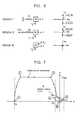
- the conventional type precise positioning system as shown in Fig. 1 is an apparatus using two-axis moving coil type linear motor 53, and it is applied to air suspension type XY stage for an X-ray exposure system.
- coarse positioning system is driven by a linear motor 53, and it is stopped by a vacuum locking mechanism 57.
- Positioning is performed by vacuum locking system to switch over coarse and fine positioning of Fig.1 (b) and by fine positioning caused by the deformation of XY fine positioning spring 61 as shown in the arrangement of fine positioning spring.
- the control block is shown in Fig.2 and Fig.3 represents the positioning sequence consisting of coarse positioning operation, locking operation and fine positioning operation.
- the conventional type precision positioning system as described above is complicated in its mechanism and is difficult to be of a small size, and the rigidity of the fixing spring by vacuum locking cannot be increased. Accordingly, natural frequency is low and the response cannot be increased. Also, because the positioning sequence is in the order of: coarse positioning ⁇ stop ⁇ locking ⁇ fine positioning, much time is required for stop and locking, and the positioning becomes long.
- the system described above is disclosed in OMROM Technics No.76, pages 285-291 (1985) -- Tsuji: "AIR BEARING GUIDED XY STAGE FOR X-RAY LITHOGRAPHY SYSTEM", and comprises the features of the preamble of Claim 1.
- the object of this invention is to offer a precise positioning system, which can be a small size and be simple structure and by which it is possible to perform the positioning with high accuracy and high resolution.
- Another object of this invention is to divide the behavioural regions of the control system and to perform coarse positioning and fine positioning for a single mechanism.
- Fig. 4 1 refers to a motor fixed part, 2 a motor coil, 3 a motor moving part, 4 a moving part, 5 a position sensor, 6 and 7 acceleration sensors, 8 a rolling guide, 9 a fixed part, 10 a position reference generator, 11 a controller, and 12 a power amplifier.
- the moving part 4, the fixed part 9 and the rolling guide 8 make up the mechanism element of the ultra-precise positioning system.
- the rollers or the balls of the rolling guide are elastically deformed to the pressure direction and to the driving direction perpendicular to it, and relative movement is obtained between the rolling guide and the fixed part 9.
- the driving force f is generated on the moving part 4 by the non-contact motor consisting of a motor fixed part 1 and a motor moving part 3 by mounting the motor moving part 3 on the moving part 4.
- the position sensor 5 is to detect the displacement x of the moving part 4 for position control, and the generator 10 generates the position reference r of the moving part 4.
- the controller 11 compares the measured position x of the moving part 4 with the position reference r, controls the driving force f by controlling the motor current i of the motor coil 2 through the power amplifier 12 and performs position control of the moving part 4.
- the acceleration sensor 6 detects the acceleration of the moving part 4 in the driving direction, while the acceleration sensor 7 detects the acceleration of the fixing part 9 in the driving direction.
- the conventional type rolling guide utilizes the region III, whereas high-velocity and ultra-precise positioning is provided by the ultra-precise positioning system of this invention by combining and utilizing the regions III and II or regions III, II and I.
- the region I (
- This system is naturally linear and has positional property, and a normal rolling does not occur. Accordingly, it has linear characteristics passing through the origin O, i.e. spring characteristics. Because the linearity of the spring characteristics of this region is very good and natural frequency is high, the nanometer positioning can be achieved by utilizing such characteristics.
- this region correspond to the conventional fine positioning mechanism, but the natural frequency is about 4 - 10 times as high as that of the conventional fine positioning mechanism.
- the region II (x 1 ⁇
- the behavior in this region II can be approximately expressed as:
- This region has the intermediate property between conventional coarse positioning system and fine positioning system.
- the region III (
- the rolling guide system has the characteristics of this region, and the position control system using the conventional rolling guide is designed by assuming the characteristics of this region. Therefore, in the position control system using the conventional rolling guide, the characteristics of the regions I and II are not positively utilized.
- the characteristics of the above regions I - III on the rolling guide are effectively utilized to achieve the ultra-precise and high speed positioning.
- the moving part 4 is driven to the position near tha reference position using the region III for the long stroke positioning. After the driving force is released near the reference position and the integral control is reset, it is shifted to the regions II and I to achieve ultra-precise positioning.
- the characteristics of the regions I and II are utilized.
- the command reference: Acceleration ⁇ Constant speed ⁇ Deceleration ⁇ Stop (Positioning) is generated as in the conventional method.
- acceleration phase is (1) ⁇ (2)
- constant velocity phase is (2) ⁇ (3)
- deceleration phase is (3) ⁇ (4) .
- This movement is carried out in the region III, and the structure of the control system is the same as the conventional system.
- control differ from the conventional system is performed from the next step according to this invention.
- the region A near the reference position as shown in Fig.7 is set and within this region the control force f is forced to zero.
- the driving force is set to 0 and the integral control is forcibly reset.
- the driving force is set to zero, the moving part is decelerated by the friction force -F 2 , and the velocity is decreased to zero, i.e. it is stopped.
- the behavior of the guide mechanism is shifted to the region II or I from the region III. From the moment (the point (5) in the figure) when the velocity is decreased to almost zero with zero driving force, the control of the regions II and I is activated, and the final positioning is performed.
- the region A where the driving force is turned to zero is set in such a manner that it is stopped within the range of
- Fig. 9 shows the block diagram of Fig. 9, where broken line 15 shows the characteristics of the mechanism.
- Fig. 10 shows an example of this region III, i.e. an example of conventional control system of the rigid body system.
- Fig. 10 (a) shows PID control
- PID control shows PID control
- PID control shows PID control
- I-PD control I-PD control
- the characteristics of mechanism in the regions I and II can be expressed as given in Fig. 11.
- the difference from the rigid body system of Fig. 9 is that there is the feedback of spring constant K. Accordingly, by adding positive feedback of gain K artificially as shown in Fig. 12, it is possible to make the characteristics of the mechanism of the regions I and II to be identical to the characteristics in the rigid body system of the region III.
- Fig. 13 shows such arrangement. This is the structure obtained by adding positive feedback of variable gain 17 to the structure of Fig. 9.
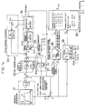
- Fig. 14 shows an example of the structure of the entire control system.
- 21 denotes a command reference generator
- 22 a PID controller
- 23 an acceleration feedback circuit
- 24 a control object
- 25 a switch
- 26 positive feedback of position
- 27 a velocity arithmetic circuit
- 28 29 and 30 region classification circuits.
- the command reference generator 21 generates the position command signal.
- the error between this position command signal r and the position signal x is inputted into PID controller 22.
- the output of PID controller 22 is turned to the driving signal u of the mechanism element 24 through the switching circuit 25.
- position positive feedback circuit 26 and acceleration feedback circuit 23 are connected.
- the acceleration feedback circuit 23 feeds back relative acceleration of the driving direction by subtracting the signal of the acceleration sensors 7 from 6 of Fig. 4.
- the position positive feedback circuit 26 is a feedback circuit of variable gain K relating to the regions I - III as explained in Fig. 13.
- the region classification circuits 28 - 30 reset the integral control of PID controller 22 relating to the regions I - III or generate the signals to switch the control in the region near the reference position.
- the region classification circuit 28 is a circuit for region classification when the driving force is set to zero forcibly near the reference as explained in Figs. 7 and 8.
- the classification signal "1" is outputted.
- the classification signal of "0" is outputted. Therefore, in case the classification signal s 1 is "1", the switch circuit 25 is set to "open” side, and the input of power amplifier of the control object 24 (driving signal u) is forcibly set to zero, and the integral control of PID controller 22 is reset.
- the region classification circuit 29 is a circuit to classify the regions I - III for the deviation d of the positioning position X r and the displacement x.
- the classification signal s 2 of "0" is outputted.
- "1" is outputted
- "2" is outputted.
- the region classification circuit 30 is a circuit for region classification to set positive feedback gain of position. In case it is classified as the region I from the classification signal s 1 of the region classification circuit 28 and from the classification signal s 2 of the region classification circuit 29, the classification signal s of "0" is outputted. In case it is classified as the region II, "1" is outputted, and "2" is outputted when classified as the region III. Therefore, the gain K of positive feedback circuit 26 is set to K 1 when the classification signal s is "0". It is set to K 2 when classification signal s is "1", and to 0 when classification signal s is "2".
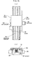
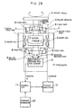
- Fig. 15 shows an example of the structure of the mechanism and the motor of the ultra-precise positioning system under experiment.
- the guiding system is a rolling type linear guide using balls.
- On the base of the fixed part guide rails 36 is mounted, and the moving parts of guide is fixed on four corners of the table 31.
- the guide is pushed by the screw mounted on the table 31, and pressure is applied on the balls.
- the motor is an AC linear motor of moving magnet type.
- Three-phase armature windings 33 is solidified with resin and is fixed on the base.
- Permanent magnets 37 are fixed under the bottom of the table 31. When electric currents are driven to armature winding 33, driving force is generated on the table 31.
- the motor is located at the center of the mechanism. If permanent magnets 37 are located as shown in Fig. 15, a moment force is not applied on the moving part. If coreless type winding is used, the fluctuations of driving force due to irregularity of magnetic circuit can be eliminated. Because the inductance of winding is extremely decreased at the same time, the motor with small electric constant and with high response can be obtained.
- 3-phase armature windings of the motor was connected as star connection, and u-phase and v-phase were driven by two linear current power amplifiers.
- the vector control is performed for i u and i v in such a manner that the magnetic field vector and the current vector are orthogonal to each other.
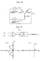
- Figs. 17 and 18 represent the examples of the solutions to this problem.
- the first is the method to stabilize by acceleration feedback.
- the mechanism has the vibration characteristics with high natural frequency.
- (2 ⁇ f n ) 2 >> 1 the acceleration is measured by a signal with relatively high level.
- vibration signals can be processed by AC circuits.
- the acceleration of the moving part and the fixed part are independently measured by piezoelectric type acceleration sensors, and the difference between them is calculated as shown in Fig. 17 (a).
- the relative acceleration is then obtained.
- T is the time constant of the first-order lag circuit
- K a is the acceleration feedback gain.
- the root loci when the acceleration is feedback through a first-order lag circuit are shown in Fig. 17 (b) for the regions I and II, and in Fig. 17 (c) for the region III.
- the damping of natural vibration can be increased, and the position loop gain can be set high. Accordingly, accuracy and response of the control are increased. Because the acceleration feedback corresponds to the first-order lag with small time constant in the region III, the characteristics of closed loop show almost no change.
- the present invention is not limited to the above description, and it is possible to make various variations and modification.
- the examples of mechanism and motor are shown on the experimental system in the above description, while there are various variation for the positioning mechanism, which is driven by a non-contact motor and is contact only with the rolling guide.
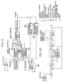
- Fig. 19 is a diagram to show the Embodiment 2 of the ultra-precise positioning system according to the present invention
- Fig. 20 is the block diagram of the coarse positioning control
- Fig. 21 gives the configuration of the fine positioning control
- Fig. 22 is the time chart of switch A and B
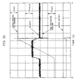
- Fig. 23 is the measured response of the moving part after the time T 1 when the motor is turned off.
- Fig. 19 differs from Fig. 14 in the following points:
- the coarse positioning controller 91 is designed with the proportional position control, and portional-integral velocity control.
- the fine positioning controller 92 is designed as a simple integral position control without velocity loop as shown in Fig. 21.
- the second-order lag filter is included in the feedback loop. This control is robust against high frequency noise because only the lag elements are used.
- the switch A is selected to 1 at the rising of the start signal of positioning as shown in the time chart of Fig. 22, and the switch B is selected to 1 in case of the positive direction positioning, and to 3 in case of the negative direction positioning.
- the switches A and B are switched over to 2 at the moment T 1 when the coarse position X c is equal to or exceeds the reference position X r + ⁇ .
- the switch A is switched to 3.
- the measured response of the moving part after the time T 1 when the motor is turned off is shown in Fig. 23.
- the behavior of the moving part is in the state of the region III by large stroke operation up to the time T 1 .
- the vibration in the region II of about 40 Hz arises and damp after about 50 ms.
- the vibration in the region I of about 200 Hz arises and settles down after 50 - 100 ms.
- the time (T 2 - T 1 ) was set to 100 ms.
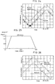
- Fig. 24 shows the step response of minimum resolution of coarse positioning control
- Fig. 25 shows the response with the maximum velocity of 200 mm/s
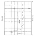
- Fig. 26 shows the step response of 1 nm of the fine positioning control.
- the minimum resolution and the maximum velocity of the coarse positioning control were determined by the performance of the coarse sensor. As is evident from Fig. 26, the positioning with resolution of better than 1 nm without backlash could be achieved. Also, it was confirned that, by switching from coarse positioning to fine positioning control in the sequence shown in the time chart of Fig. 22, long stroke and high speed positioning can be performed by coarse positioning control and the positioning with the resolution of better than 1 nm can be achieved by fine positioning control.
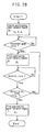
- Fig. 27 is a diagram to show the Embodiment 3 of the ultra-precision positioning system of this invention, and Fig. 28 is to explain the positioning sequence.
- the control to turn the motor off i.e. to set the driving force to zero, and the correction of the deformation ⁇ of rolling guide are accomplished continuously with smooth response.
- a circuit to achieve the smooth switching is given in Fig. 27. This shows the control circuit for the regions III and II. The proportional position control and proportional-integral control are adopted.
- R 7 and C 2 make up the first-order lag circuit of the time constant R 7 C 2 (s), and the step change of ⁇ ⁇ 0 is smooth change.
- the voltage compensating the friction force is charged on the integration capacitor C. This capacitor is shorted by SW 2 , and discharged through R 6 . Thus, the force is set continuously to zero.
- the range of the region I is about ⁇ 100 nm in the experimental mechanism. It is problem whether the final positioning position x r is included in the region I or not when the table settles in the region I after the positioning in the regions III and II. If it is included, it is possible to switch from the coarse positioning to the fine positioning control in the region I. If not included, however, new positioning should be performed with the positioning position x r as goal. Fig. 28 shows the sequence of such positioning.
- Fig. 29 shows a sample structure of this invention applied to a rotary positioning table
- Fig. 30 is a section view of a roller bearing of Fig. 29 along the line A - A′.
- a rotor 3 is mounted on a rotary table 4, and rotary table 4 is controlled by giving rotary torque ⁇ directly by a perfectly non-contact type motor composed of rotor 3, motor coil 2 and motor fixed part 1.
- the position sensor 5 is to measure the angular position (rotating angle) ⁇ of the rotary table 4, and the command reference generator 10 is to generate the position reference r of the rotary table 4.
- the controller 11 performs the position control of the rotary table 4 by comparing the rotating angle ⁇ with the reference r and by controlling the current i, flowing to the motor coil 2 by power amplifier 12, thus operating the rotary torque ⁇ .
- the position x (x 0 , x 1 , x 2 , ⁇ , ) is the position ⁇ ( ⁇ 0 , ⁇ 1 , ⁇ 2 , ⁇ , )
- friction force F (F 1 , F 2 ) is friction torque T (T 1 , T 2 )
- the mass M is inertia J, it becomes the same as the linear movement system.
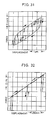
- Fig. 31 shows the force-to-displacement relationship when transitions between the regions I and II occur
- Fig. 32 is a partially enlarged figure of Fig. 31
- Fig. 33 shows the force-to-displacement relationship when transitions in the regions II and III occur
- Fig. 34 shows friction-force-to-velocity relationship of the rolling guide.
- whisker shape responses indicate transitions between the regions I and II. Since the all wiskers have the same shape, it is evident that the characteristics of the region I do not vary for position changes.
- the external loop indicates the characteristics of the region III, and the whiskers indicate the characteristics of the region II. Thus, the characteristics of the region II also do not vary for position changes. In accelerating, any static friction force does not exist as shown in Fig. 34.
- a rolling guide system is adopted as the guide unit according to the present invention.
- the coarse positioning system and the fine positioning system are automatically and intrinsically achieved by the characteristics of the rolling guide.
- the positioning with high resolution and high speed can be accomplished by utilizing all properties of the regions I, II and III possessed by the rolling guide, by moving toward the positioning goal point by the region III where friction force is in a constant and steady rolling status, and by performing the positioning in the region I of the spring with high rigidity.
Landscapes
- Control Of Position Or Direction (AREA)
Claims (7)
- Hochpräzises Positioniersystem, umfassend ein bewegliches Teil (4) und ein festes Teil (9), die nur über eine Rollführung (8) gegenseitigen Kontakt haben, auf welche Kontaktdruck P ausgeübt wird, eine Einrichtung (1 - 3) zum Antreiben des beweglichen Teils (4) durch einen Nichtkontaktmotor, eine Positionsmeßeinrichtung (5) zum Messen der Position (x) des beweglichen Teils (4), einen Positionsreferenzgenerator (10) zur Erzeugung der Referenzposition (r) des beweglichen Teils (4) und ein Positionierkontrollsystem (11, 12) zum Kontrollieren der Position des beweglichen Teils (4) durch Vergleich der gemessenen Position (x) mit der Referenzposition (r), dadurch gekennzeichnet, daß das Positionskontrollsystem (11, 12) so ausgebildet ist, daß es in der Lage ist, einen Bewegungsbereich II des beweglichen Teils (4), in dem die Verschiebung des beweglichen Teils (4) von der Antriebskraft abhängt, die von der Antriebseinrichtung (1 - 3) ausgeübt wird, und einen Bewegungsbereich III festzustellen, in welchem die Reibungskraft der Rollführung (8) gesättigt ist und ein normales Rollen stattfindet, und daß das genannte Kontrollsystem (11, 12) darüber hinaus in der Lage ist, eine Grobpositoniereinstellung im Bereich III und eine Feinpositioniereinstellung im Bereich II durchzuführen.
- Hochpräzises Positioniersystem nach Anspruch 1, bei welchem die mechanischen Charakteristika der Rollführung (8) derart ausgebildet sind, daß innerhalb des Bereichs II ein Bereich I existiert, innerhalb dessen die Bewegung des beweglichen Teils (4) einer reversiblen und elastischen Federcharakteristik folgt.
- Hochpräzises Positioniersystem nach Anspruch 2, bei welchem das Positionierkontrollsystem eine Einrichtung (16) umfaßt zur Klassifizierung des Bewegungsbereichs des beweglichen Teils in eine der drei Bewegungsbereiche (I, II, III) und eine Einrichtung (17) zur Auswahl einer von drei Positionierkontrollen (K1, K2, 0) entsprechend dem klassifizierten Bereich.
- Hochpräzises Positioniersystem nach einem der Ansprüche 1 bis 3, bei welchem die Anordnung so getroffen ist, daß die Rollführung (8) während der Grobpositionierung im Bereich III deformiert wird, und daß das genannte Kontrollsystem (Fig. 19) darüber hinaus so ausgebildet ist, um anzunehmen, daß die Deformation Δ ist, und wobei die Positionierstellung Xr ist, um die Grobreferenzposition r zu korrigieren als

- Hochpräzises Positioniersystem nach einem der Ansprüche 1 bis 3, bei dem die Anordnung so getroffen ist, daß das Positionierkontrollsystem beurteilt, ob die Grobpositionierung im Bereich III sich der Positionierstellung Xr nähert und durch Entladen eines Integrationskondensators (C) eines proportionalintegralen Kontrollkreises über einen Widerstand (R6) den Bereich von III nach II oder von III nach II und I transferiert (Fig. 27).
- Hochpräzises Positioniersystem nach einem der Ansprüche 1 bis 3, bei dem die Anordnung so getroffen ist, daß das Positionierkontrollsystem in der Lage ist zu beurteilen, daß die Grobpositionierung im Bereich III sich der Positionierungsstellung Xr nähert und, durch zwangsweises Zurücksetzen der Kraft des Motors auf Null für eine bestimmte Zeitperiode, den Bereich von III nach II oder von III nach II und I transferiert (Fig. 22).
- Hochpräzises Positioniersystem nach Anspruch 2 oder 3, wobei das Positionierkontrollsystem so angeordnet ist, daß es beurteilen kann, daß die Positionierstellung Xr innerhalb des Bereichs I liegt, wenn die Positionierung in den Bereichen III und II vollendet ist und in den Bereich I verbracht ist, und daß, wenn die Positionierungsstellung innerhalb des Bereichs I sich befindet, eine Feinpositionierung im Bereich I durchgeführt wird und dann, falls sie nicht im Bereich I ist, eine neue Positionierung im Bereich II in Richtung auf die Positionierungsstellung Xr wiederholt durchgeführt wird (Fig. 28).
Applications Claiming Priority (2)
| Application Number | Priority Date | Filing Date | Title |
|---|---|---|---|
| JP13957889 | 1989-05-31 | ||
| JP139578/89 | 1989-05-31 |
Publications (3)
| Publication Number | Publication Date |
|---|---|
| EP0401018A2 EP0401018A2 (de) | 1990-12-05 |
| EP0401018A3 EP0401018A3 (de) | 1992-09-23 |
| EP0401018B1 true EP0401018B1 (de) | 1996-09-18 |
Family
ID=15248522
Family Applications (1)
| Application Number | Title | Priority Date | Filing Date |
|---|---|---|---|
| EP90305943A Expired - Lifetime EP0401018B1 (de) | 1989-05-31 | 1990-05-31 | Hochpräzises Positioniersystem |
Country Status (4)
| Country | Link |
|---|---|
| US (1) | US5079493A (de) |
| EP (1) | EP0401018B1 (de) |
| JP (1) | JPH07122830B2 (de) |
| DE (1) | DE69028574T2 (de) |
Families Citing this family (18)
| Publication number | Priority date | Publication date | Assignee | Title |
|---|---|---|---|---|
| US5694016A (en) * | 1989-09-26 | 1997-12-02 | Robert Bosch Gmbh | Method for controlling a servo system having friction |
| JP2721757B2 (ja) * | 1991-05-24 | 1998-03-04 | 工業技術院長 | 位置決め制御方法及び装置 |
| US5196745A (en) * | 1991-08-16 | 1993-03-23 | Massachusetts Institute Of Technology | Magnetic positioning device |
| US5175456A (en) * | 1991-09-25 | 1992-12-29 | Systems, Machines, Automation Components Corp. | Workpiece transporter |
| US5327059A (en) * | 1992-09-24 | 1994-07-05 | Archive Corporation | Tape drive capstan motor servo system with static friction compensation |
| JP2822809B2 (ja) * | 1992-09-30 | 1998-11-11 | 三菱電機株式会社 | 位置制御方法および位置制御装置 |
| EP0783662B1 (de) * | 1994-08-27 | 1999-04-07 | International Business Machines Corporation | Feineinstellungsapparat mit atomarer auflösung |
| JP3239060B2 (ja) * | 1996-01-31 | 2001-12-17 | シャープ株式会社 | モータ制御装置 |
| WO2000052543A1 (en) * | 1999-03-03 | 2000-09-08 | Kabushiki Kaisha Yaskawa Denki | Positioning control method |
| JP2003502000A (ja) * | 1999-06-01 | 2003-01-14 | コンティニューム コントロール コーポレイション | 機械的変動から電力を取出す方法及びシステム |
| EP1529252A1 (de) * | 2002-08-07 | 2005-05-11 | Koninklijke Philips Electronics N.V. | Verfahren und einrichtung zur identifikation der parameter eines elektromechanischen systems |
| US20050093502A1 (en) * | 2003-10-31 | 2005-05-05 | Nikon Corporation | Stage with isolated actuators for low vacuum environment |
| JP4721835B2 (ja) * | 2005-09-06 | 2011-07-13 | 株式会社リコー | 位置決め制御装置及びそれを備えた画像形成装置 |
| JP4643509B2 (ja) * | 2006-07-14 | 2011-03-02 | 株式会社東芝 | 追尾照準装置 |
| JP4540727B2 (ja) * | 2008-07-31 | 2010-09-08 | 山洋電気株式会社 | モータ制御装置 |
| DE112010001903A5 (de) * | 2009-05-05 | 2012-06-14 | Basf Se | Vorrichtung zur Ausrichtung elner Oberfiäche mindestens eines Gegenstands |
| DE102012014558B4 (de) | 2012-07-24 | 2014-02-20 | Datacon Technology Gmbh | Kinematisches Haltesystem für einen Bestückkopf einer Bestückvorrichtung |
| JP2016095746A (ja) * | 2014-11-17 | 2016-05-26 | Thk株式会社 | 転がり機構を用いた位置決め制御方法及び装置 |
Family Cites Families (16)
| Publication number | Priority date | Publication date | Assignee | Title |
|---|---|---|---|---|
| US3889164A (en) * | 1973-01-24 | 1975-06-10 | Handotai Kenkyu Shinkokai | Position control system using magnetic forces for correcting the inclination of a controlled member including a torsional mounting |
| JPS547078A (en) * | 1977-06-16 | 1979-01-19 | Oki Electric Ind Co Ltd | Automatic positioning method to inherent position of machine in numerical control |
| JPS5847043B2 (ja) * | 1979-02-07 | 1983-10-20 | 株式会社日立製作所 | 位置制御方式 |
| CH651948A5 (de) * | 1980-08-17 | 1985-10-15 | Maag Zahnraeder & Maschinen Ag | Positionsregelvorrichtung mit einer digitalen inkrementellen messeinrichtung. |
| JPS5968003A (ja) * | 1982-10-13 | 1984-04-17 | Toyoda Mach Works Ltd | 数値制御工作機械の非常機械原点復帰装置 |
| DD222105A1 (de) * | 1983-12-01 | 1985-05-08 | Zeiss Jena Veb Carl | Anordnung zur positionierung von messobjekten bei waagerecht antastenden einkoordinatenmessgeraeten |
| GB8518609D0 (en) * | 1985-07-23 | 1985-08-29 | Ae Plc | Machine toll control systems |
| JPS62229307A (ja) * | 1986-03-31 | 1987-10-08 | Canon Inc | 位置決め制御装置 |
| US4724370A (en) * | 1986-10-14 | 1988-02-09 | Konishiroku Photo Industries Co., Ltd. | Servo system for a disk drive |
| JPS63148315A (ja) * | 1986-12-12 | 1988-06-21 | Fanuc Ltd | サ−ボモ−タ制御装置 |
| JPS63157684A (ja) * | 1986-12-19 | 1988-06-30 | Tokyo Electric Co Ltd | リニアモ−タの位置決め制御方法 |
| US4843293A (en) * | 1987-02-02 | 1989-06-27 | Research Development Corporation | Apparatus for controlling servo system employing piezo-electric actuator |
| JPS6426212A (en) * | 1987-07-22 | 1989-01-27 | Honda Motor Co Ltd | Positioning system for moving body by industrial robot |
| JP2519968B2 (ja) * | 1988-03-22 | 1996-07-31 | オ−クマ株式会社 | 電動機による軸の位置制御方式 |
| JPH07120216B2 (ja) * | 1988-10-21 | 1995-12-20 | 新技術事業団 | 位置制御方法 |
| US4914725A (en) * | 1989-07-10 | 1990-04-03 | International Business Machines Corporation | Transducer positioning servo mechanisms employing digital and analog circuits |
-
1990
- 1990-04-27 JP JP2113802A patent/JPH07122830B2/ja not_active Expired - Fee Related
- 1990-05-31 DE DE69028574T patent/DE69028574T2/de not_active Expired - Fee Related
- 1990-05-31 US US07/531,229 patent/US5079493A/en not_active Expired - Lifetime
- 1990-05-31 EP EP90305943A patent/EP0401018B1/de not_active Expired - Lifetime
Also Published As
| Publication number | Publication date |
|---|---|
| EP0401018A3 (de) | 1992-09-23 |
| US5079493A (en) | 1992-01-07 |
| EP0401018A2 (de) | 1990-12-05 |
| JPH07122830B2 (ja) | 1995-12-25 |
| JPH0373007A (ja) | 1991-03-28 |
| DE69028574T2 (de) | 1997-04-17 |
| DE69028574D1 (de) | 1996-10-24 |
Similar Documents
| Publication | Publication Date | Title |
|---|---|---|
| EP0401018B1 (de) | Hochpräzises Positioniersystem | |
| US6130517A (en) | Magnetic actuator producing large acceleration on fine stage and low RMS power gain | |
| Futami et al. | Nanometer positioning and its micro-dynamics | |
| Kiong et al. | Precision motion control: design and implementation | |
| US6525446B1 (en) | Electrostatic actuator driving method and mechanism, using rigidity retention as a parameter | |
| JP3217522B2 (ja) | 精密位置決め装置 | |
| Pelta | Two-axis Sawyer motor for motion systems | |
| US5359154A (en) | Conveyor apparatus having plural conveyors with equalized conveying speeds controlled by an inverter means | |
| Pritschow et al. | Direct drives for high-dynamic machine tool axes | |
| WO2000045059A1 (en) | Controlled magnetic bearing device | |
| Quaid et al. | 3-DOF closed-loop control for planar linear motors | |
| US5305158A (en) | Positioning control apparatus | |
| EP0488805B1 (de) | Linearmotorvorrichtung mit einem Bauteil zur Unterdrückung von Schwingungen | |
| US6448723B1 (en) | Stage system and exposure apparatus | |
| JPH06120105A (ja) | 位置決め装置及びこれに用いられるピエゾアクチュエータ駆動装置 | |
| JPH11282538A (ja) | サーボ装置 | |
| JPS6056075B2 (ja) | パルスモ−タを用いた駆動装置 | |
| JPH05333936A (ja) | 制御回路および位置決めテーブル装置 | |
| JP3179843B2 (ja) | 位置決め制御方法および装置 | |
| JP2770729B2 (ja) | ヘッドアクセス制御方法 | |
| JP2780847B2 (ja) | コイルを可動部に用いた駆動装置 | |
| JPH0798256A (ja) | 駆動力測定装置 | |
| Shinnaka | A new position‐sensorless position control method for high‐speed spindle systems | |
| Melkote et al. | Output feedback control of a three degree-of-freedom linear stepper motor with position measurements only | |
| Takahashi et al. | A simple positioning servo system by breaking control |
Legal Events
| Date | Code | Title | Description |
|---|---|---|---|
| PUAI | Public reference made under article 153(3) epc to a published international application that has entered the european phase |
Free format text: ORIGINAL CODE: 0009012 |
|
| AK | Designated contracting states |
Kind code of ref document: A2 Designated state(s): AT BE CH DE DK ES FR GB GR IT LI LU NL SE |
|
| RBV | Designated contracting states (corrected) |
Designated state(s): DE GB |
|
| PUAL | Search report despatched |
Free format text: ORIGINAL CODE: 0009013 |
|
| AK | Designated contracting states |
Kind code of ref document: A3 Designated state(s): AT BE CH DE DK ES FR GB GR IT LI LU NL SE |
|
| RHK1 | Main classification (correction) |
Ipc: G05B 19/21 |
|
| 17P | Request for examination filed |
Effective date: 19921102 |
|
| 17Q | First examination report despatched |
Effective date: 19940927 |
|
| GRAH | Despatch of communication of intention to grant a patent |
Free format text: ORIGINAL CODE: EPIDOS IGRA |
|
| RAP1 | Party data changed (applicant data changed or rights of an application transferred) |
Owner name: KABUSHIKI KAISHA YASKAWA DENKI Owner name: RESEARCH DEVELOPMENT CORPORATION OF JAPAN |
|
| GRAH | Despatch of communication of intention to grant a patent |
Free format text: ORIGINAL CODE: EPIDOS IGRA |
|
| GRAA | (expected) grant |
Free format text: ORIGINAL CODE: 0009210 |
|
| AK | Designated contracting states |
Kind code of ref document: B1 Designated state(s): DE GB |
|
| REF | Corresponds to: |
Ref document number: 69028574 Country of ref document: DE Date of ref document: 19961024 |
|
| PLBE | No opposition filed within time limit |
Free format text: ORIGINAL CODE: 0009261 |
|
| STAA | Information on the status of an ep patent application or granted ep patent |
Free format text: STATUS: NO OPPOSITION FILED WITHIN TIME LIMIT |
|
| 26N | No opposition filed | ||
| PGFP | Annual fee paid to national office [announced via postgrant information from national office to epo] |
Ref country code: GB Payment date: 20010516 Year of fee payment: 12 |
|
| PGFP | Annual fee paid to national office [announced via postgrant information from national office to epo] |
Ref country code: DE Payment date: 20010525 Year of fee payment: 12 |
|
| REG | Reference to a national code |
Ref country code: GB Ref legal event code: IF02 |
|
| PG25 | Lapsed in a contracting state [announced via postgrant information from national office to epo] |
Ref country code: GB Free format text: LAPSE BECAUSE OF NON-PAYMENT OF DUE FEES Effective date: 20020531 |
|
| PG25 | Lapsed in a contracting state [announced via postgrant information from national office to epo] |
Ref country code: DE Free format text: LAPSE BECAUSE OF NON-PAYMENT OF DUE FEES Effective date: 20021203 |
|
| GBPC | Gb: european patent ceased through non-payment of renewal fee |
Effective date: 20020531 |