EP0401023A2 - Système d'enregistrement d'images et appareil pour celui-ci - Google Patents
Système d'enregistrement d'images et appareil pour celui-ci Download PDFInfo
- Publication number
- EP0401023A2 EP0401023A2 EP90305956A EP90305956A EP0401023A2 EP 0401023 A2 EP0401023 A2 EP 0401023A2 EP 90305956 A EP90305956 A EP 90305956A EP 90305956 A EP90305956 A EP 90305956A EP 0401023 A2 EP0401023 A2 EP 0401023A2
- Authority
- EP
- European Patent Office
- Prior art keywords
- image
- density
- data
- recording
- dots
- Prior art date
- Legal status (The legal status is an assumption and is not a legal conclusion. Google has not performed a legal analysis and makes no representation as to the accuracy of the status listed.)
- Granted
Links
Images


Classifications
-
- H—ELECTRICITY
- H04—ELECTRIC COMMUNICATION TECHNIQUE
- H04N—PICTORIAL COMMUNICATION, e.g. TELEVISION
- H04N1/00—Scanning, transmission or reproduction of documents or the like, e.g. facsimile transmission; Details thereof
- H04N1/40—Picture signal circuits
- H04N1/40087—Multi-toning, i.e. converting a continuous-tone signal for reproduction with more than two discrete brightnesses or optical densities, e.g. dots of grey and black inks on white paper
-
- H—ELECTRICITY
- H04—ELECTRIC COMMUNICATION TECHNIQUE
- H04N—PICTORIAL COMMUNICATION, e.g. TELEVISION
- H04N1/00—Scanning, transmission or reproduction of documents or the like, e.g. facsimile transmission; Details thereof
- H04N1/40—Picture signal circuits
- H04N1/405—Halftoning, i.e. converting the picture signal of a continuous-tone original into a corresponding signal showing only two levels
Definitions
- the present invention relates to an image recording method and an apparatus therefor, for example, to an image recording method and an apparatus therefor for recording an image by a recording head which discharges ink.
- the gradient in the highlight portion can be improved, the granular touch of the dots can be reduced and the image quality can thereby be improved simply by changing the binary processing for a trinary processing.
- the reason for this lies in that applying low density ink to the highlight portion can remove the noise due to a sole dot.
- Each of the output signal levels after separated by a dark/light separation table is supplied to a binary circuit in which it is converted into an on/off recording signal.
- the binary circuits are arranged to have the same structure for both dark and light ink.
- an object of the present invention is to provide an image reproducing method from which an output image can be recorded in which granular portion is removed and high resolution and high gradient are realized.
- an image recording method arranged such that high density dots are recorded by raising its resolution with respect that for the low density dots.
- an image recording method for recording a gradient image by combining dots of different density comprising: a process in which image data is received; a process in which data corresponding to dots of each density is generated in accordance with the value of the received image data; and a process in which data corresponding to the thus generated dots of each density is converted so as to have resolution which corresponds to the dots of each density.
- Another object of the present invention is to provide an image recording apparatus capable of recording an output image in which granular touch can be prevented and which exhibits excellent resolution and gradient.
- an image recording apparatus for recording a gradient image by combining dots of different density, comprising: receiving means for receiving image data; data generating means for generating data which corresponds to the dots of each density in accordance with the value of the image data received by the receiving means; and conversion means for converting each data which corresponds to the dots of each density generated in the data generating means so as to have resolution which corresponds to the dots of each density.
- an image recording apparatus for recording a gradient image by combining dots of different density, comprising: receiving means for receiving image data; data generating means for generating data which corresponds to the dots of each density in accordance with the value of the image data received; compensating means for compensating data which corresponds to the dots of each density generated in the data generating means in a proportion which bases upon the resolution of each of the densities; recording means for recording the image in accordance with the resolution for each of the densities; and control means for controlling in such a manner that data which corresponds to the dots of each density compensated by the compensating means is recorded by the recording means.
- Another object of the present invention is to provide an image recording apparatus for recording image by discharging ink of different densities capable of recording an output image without granular touch and exhibiting high resolution and gradient.
- an image recording apparatus for recording a gradient image by combining dots of at least two different densities, comprising: receiving means for receiving image data; first data generating means for generating image data for dark ink in accordance with the value of the image data received by the receiving means; second data generating means for generating image data for light ink in accordance with the value of the image data received by the receiving means; first conversion means for converting the image data for dark ink generated by the first data generating means into a binary signal with the resolution made critical; second conversion means for converting the image data for light ink generated by the second data generating means into a binary signal with the gradient made critical; and recording means for controlling the discharge of ink of each density in accordance with the binary signal converted by the first and second conversion means and recording the image.
- an image recording apparatus for recording a gradient image by combining dots of a plurality of different densities, comprising: receiving means for receiving image data; data generating means for generating image data which corresponds to ink of each density in accordance with the value of the image data received; compensating means for compensating image data generated by the data generating means in such a manner that image data for high density ink is subjected to higher compensation rate; conversion means for converting image data for each ink of each density compensated by the compensating means into a binary signal; recording means for recording ink in such a manner that the higher the density of the ink is, the larger the resolution becomes; and control means for controlling in such a manner that the recording means performs the recording in accordance with the binary signal for each ink of each density converted by the conversion means.
- the structure of the bubble jet printer according to the embodiments of the present invention has 8 recording heads therein.
- the recording heads are mounted on a carriage at a predetermined interval, the carriage performing the main scanning operation. Furthermore, each of the 8 recording heads has a predetermined number of nozzles in the sub-scanning direction.
- each of recording color components C (cyan), M (magenta), Y (yellow) and K (black) is arranged to have dark tone and light tone.
- Fig. 1 is a circuit diagram for processing an image performed in a copying machine according to this embodiment.
- Reflected light obtained by applying halogen light or the like to a document placed on a document plate is received by a CCD 20 which is a sensor for each of the color components via a rod lens array.
- the CCD 20 outputs analog data for each of the color components R (Red), G (Green) and B (Blue). Data for each of the color components is held in a sample hold circuit for a predetermined time.
- Each of the voltage levels thus held is, by an A/D converter 21, converted into 8-bit digital data.
- each of data is logarithmically converted into C, M and Y data (8 bits respectively) by a log converter 22.
- 8-bit C, M and Y data is subjected to a masking and a basic color removal in a masking/UCR processing portion 23 so that colors C, M, Y and K (8 bits) are obtained.
- Data for colors C, M, Y and K are fetched by a dark/light separation table 24 disposed next to the masking/UCR processing portion 23.
- the dark/light separation table 24 receives, for example, data for color C and outputs data C′ (8 bits) for light ink and data C ⁇ for dark ink after dividing the data for color C. Data for the other color components are similarly outputted after divided into data for dark ink and light ink.
- the dark/light separation table 24 is a so-called "Look-up" table and the detailed operation will be later.
- Data for light ink (C′, M′, Y′ and K′) outputted from the separation table 24 are distributed to a binary circuit 26, while data for dark ink (C ⁇ , M ⁇ , Y ⁇ and K ⁇ ) are distributed to another binary circuit 25.
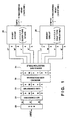
- the binary circuit 25 binarizes supplied dark ink data Y ⁇ , M ⁇ , C ⁇ and K ⁇ for one pixel by its bayer type binary matrix pattern having a structure (4 x 4) x 2 as shown in Fig. 2A.
- the above-described bayer type binary matrix pattern is one of binary matrix patterns exhibiting an excellent resolution based on the organizational dither method.
- the binary circuit 26 binarizes supplied light ink data Y′, M′, C′ and K′ by its half tone binary matrix pattern having a structure (4 x 4) x 2 as shown in Fig. 2B.
- the half tone binary matrix pattern is one of binary matrix pattern exhibiting excellent gradient expression capability based on the organizational dither method. Then, each of data is outputted in the form of data (a one bit signal) for turning on/off a recording head.
- recording head on/off data outputted from the binary circuits 25 and 26 are synchronized to one another by a delaying buffer (omitted from illustration).
- 17 x 17 patches are formed by combining dark and light ink in such a manner that the quantity of the dark ink is classified into 0 to 16 degrees to which 0 to 16 degrees of light ink are added respectively. That is patches of the type in which light ink is changed with respect to the quantity degree "0" of the dark ink are prepared. Furthermore, patches corresponding to other dark ink quantity degrees "1 to 16" are prepared. Then, each of the batches is colorimetrically analyzed by using a "Color Analyzer CA-35" manufactured by Murakami Shikisaisha.
- The, thus obtained density data is plotted as the change of data for light ink with the dark ink fixed so that the relationship between the combination of the dark and the light ink and the density is obtained.
- the combination of data for the dark and light ink was obtained with which a linear relationship can be established between the sole color input data and the result of the colorimetrical analysis.
- the conversion graph of the dark/light separation table 24 thus obtained is shown in Fig. 3, where symbol C represents the separation characteristics with respect to cyan.
- the other color components are processed similarly to the above-described process.
- the dark/light separation table 24 includes 4 look-up tables having characteristics as shown in Fig. 3.
- higher dye density ink is used when the input data represents high density with excellent resolution maintained in the result of the recording.
- the dye density of C-ink 0.7%-light ink and 2.5% dark ink were employed.
- colors M, Y and K the tables having the conversion characteristics which meet the corresponding characteristics of the colors were employed.
- the density of the dye in the dark ink and the light ink for each of the color ink are as follows: In the case of M: light: 0.6% dark: 2.5% In the case of Y: light: 0.7% dark: 2.0% In the case of K: light: 1.0% dark: 3.0%
- the recording order of the dark ink and the light ink was arranged as dark ⁇ light. And the recording order of the color components was arranged as C ⁇ M ⁇ Y ⁇ K so as to overlap successively.
- the present invention is not limited to the above-described order and the dye density. They may be changed to meet the type of the image to be outputted or the type of the dye employed. However, if the density of the dye for the dark and the light ink is changed, the conversion characteristics of the dark/light separation table must, of course, be changed.
- color photograph (silver salt) images or half tone image (175 lines) were outputted, resulting an excellent productionality obtained in the skin color portions and the thin lines portions of characters.
- dark ink data and light ink data for each of the color components are received so as to be subjected by the dither processing in the binary circuits 25 and 26.
- data for dark ink is binarized by the dither matrix patterns exhibiting an excellent resolution
- data for light ink is binarized by the dither matrix exhibiting excellent gradient expression capability.
- the present invention is not limited to the above-described description.
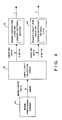
- a structure may be employed in which data for dark ink is binarized by the error diffusion method and data for light ink is binarized by the density pattern method.
- Fig. 4 is a block diagram for use in the above-described case.
- reference numeral 41 represents an image processing circuit including the CCD 20 to the masking/UCR processing portion 23 shown in Fig. 1.
- Reference numeral 42 represents a dark/light separation table which is the same as that represented by reference numeral 24 shown in Fig. 1.
- Reference numeral 43 represents a binary circuit acting on the basis of the density pattern method and 44 represents a binary circuit acting on the basis of the error diffusion method.
- a matrix shown in Fig. 5 is used in the above-described error diffusion method.
- symbol "*" represents a subject pixel and the numerals in the matrices represent the diffusion coefficients. Since the processing according to the density pattern method and the error diffusion method are well known, their descriptions are omitted here.
- a black ink quadruple recording is realized by arranging the types of the ink to be light ink (dye density: 0.5%), medium ink (dye density: 1.0%) and dark ink (dye density: 3.0%).
- Fig. 6 is a perspective view which illustrates a cartridge of a type in which a dark, a medium and a light ink cartridges are integrally provided.
- reference numeral 5 represents a light ink cartridge
- 9 represents a medium ink cartridge
- 6 represents a dark ink cartridge.
- the image can be formed when a carriage 7 on which the above-described three cartridges are moved in the main scanning direction as designated by an arrow shown in the drawing. Therefore, the ink applying order is arranged as: dark, medium and light.
- the above-described apparatus is arranged in such a manner that the dark ink cartridge 6 is connected to a head displaying a recording density of 400 dpi, the medium ink cartridge 9 is connected to that displaying a recording density of 300 dpi and the light ink cartridge 5 is connected to that displaying a recording density of 200 dpi.
- the recording side of the recording head of each of the cartridges 6, 9 and 5 has a plurality of ink discharging port (nozzles) arranged vertically to form a line.
- the ration of the number of the nozzles for the recording head for the light ink, that for the medium ink and that for the dark ink is arranged to be 2:3:4 so as to correspond to the resolution.
- the distance between the adjacent nozzles provided on the recording head for the light ink is arranged to be twice of that for the dark ink.
- the distance between the adjacent nozzles provided on the recording head for the medium ink is arranged to be 1.5 time that for the dark ink.
- the control of the resolution in the main scanning direction is performed by controlling the timing of a ink discharge instruction signal (an operation signal) to be supplied to each of the recording heads.
- a ink discharge instruction signal an operation signal
- the carriage 7 moves at a constant speed, it is arranged that the number of the operation signals to be supplied to the medium ink recording head per unit time is 3f, that supplied to the dark ink recording head per unit time is 4f when the number of the operation signals to be supplied to the light ink recording head per unit time is 2f.
- the carriage according to the first embodiment of the present invention has 8 cartridges shown in Fig. 6.
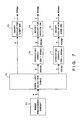
- FIG. 7 An example of the structure of the image processing circuit for the apparatus according to a third embodiment is shown in Fig. 7.
- reference numeral 71 represents a circuit to be subjected to the same processings as those subjected to the image processing circuit 41 shown in Fig. 4.
- Reference numeral 72 represents a dark/medium/light separation table which receives input data for K (8 bits) and generates data (8 bits) for dark, medium and light ink.
- the data for K supplied through the image processing circuit 71 according to the third embodiment of the present invention display a resolution of 200 dpi.
- Data for light ink separated by the dark/medium/light separation table 72 is, as it is, fetched by a light ink binary circuit 73 in which it is converted into an on/off signal with which light ink is applied. That is, it is outputted to the light ink binary circuit 73 with maintaining the same resolution as that at the time of the input.
- Data for medium ink is converted from data for a resolution of 200 dpi to data for a resolution of 300 dpi by a conversion circuit 76 so as to be fetched by a medium ink binary circuit 74.
- Data for dark ink is converted from data for a resolution of 200 dpi to data for a resolution of 400 dpi by a conversion circuit 77 so as to be fetched by a medium ink binary circuit 75.
- the above-described conversion circuits 76 and 77 are constituted by compensating circuits for performing an compensating processing by using the adjacent pixel data items. Assuming that image data (pixel data) to be supplied to a time series is A, B, C, D,.., the conversion circuit 76 outputs data in a sequential order as A, (A + B)/2, B, C, (C + D)/2, D,..., while the conversion circuit 77 outputs data in a sequential order as A, (A + B)/2, B, (B + C)/2, C, (C + D)/2, D,...
- the ratio of the compensation that is the ratio between the number of the output pixels and the number of the input pixels is made coincide with the ratio between the resolution.
- each of the conversion circuits 76 and 77 includes a line memory having a proper capacity.
- Fig. 9 illustrates an example of an imaging circuit positioned behind the binary circuits 73 to 75 according to this embodiment.
- reference numerals 91 to 93 represent buffer memories for temporarily storing image data supplied from the binary circuits 73 to 75.
- Reference numerals 94 to 96 represent latches for holding binary information to be recorded by an operation signal.
- Reference numeral 100 represents a driver for outputting the operation signal to signal lines 100a, 100b and 100c at the above-described timing.
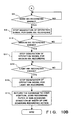
- step S2 it is determined whether or not a dark ink recording head 99 of the carriage 7 has reached a position at which the recording starts. The above-described determination is arranged to be made by whether or not a sensor fixed to the printing portion has detected a specific portion of the carriage 7. It may, of course, be made by another means. If it is determined that the carriage 7 has been moved to the dark ink image recording start position, the CPU 90 instructs the driver 100 to start generation of operation signals to be supplied to the dark ink recording head 99 via the signal line 100c.
- the dark ink recording head 99 When the level of the signal line 100c has become active, the dark ink recording head 99 performs one action of discharging ink liquid in accordance with information latched by the latch 96. Whenever the above-described operation has been completed, next image data is arranged to be read by the latch 9 from the buffer memory 93.
- the CPU 90 controls the start of the medium ink recording.
- the reason for the fact that the recording start time is different for the types of ink lies in that the recording heads are disposed at predetermined intervals.
- step S8 the determination of this is made. If the determination is YES in step S8, the flow advances to step S9 in which the generation of the operation signal for the dark ink recording is stopped. Then, in steps S10 to S13, similar operation is conducted for the medium and the light ink recording heads. In step S14, the carriage 7 is then moved in the reversed direction so as to reach its home position and as well recording paper 1 is fed in the scanning direction by a distance corresponding to the one scanning recording action.
- the recording heads 97 to 99 are positioned away from one another.
- the read from each of the buffer memories with respect to one scanning recording is arranged to be delayed before latched by each of the latches.
- the operation signals to be supplied to the recording heads are generated in the driver 100 according to the above-described embodiments, the operation signals may be arranged to be outputted from the CPU 90.
- the reason for this lies in that the number of predetermined clocks may be counted so as to generate the operation signals.
- the structure of the printing portion according to the first and the second embodiments are omitted from a detail description, it can be considered to be substantially the same as that according to the third embodiment of the present invention shown in Fig. 9 except for the number of the recording heads.
- a structure can be employed in which the nozzles for each of the recording heads are disposed at the same intervals.
- the difference from the third embodiment lies in that the operation signals are supplied to the recording heads at the same intervals.
- the description is made on the assumption that the ink discharging nozzles for the recording head have the same inner diameter (the diameter of the orifice).
- a structure may be employed in which orifices of 30 ⁇ for dark ink and those of 40 ⁇ are used.
- the warmtone of the heads is changed. That is, the warmtone is arranged to be low for the dark image, while the same is arranged to be high for the light image so as to change the diameter of the droplets (the diameter of the droplets are, of course, made to be small for the dark image and large for the light image).
- three or more density ink and recording heads may be employed.
- the highest dye density be made correspond to the greatest resolution by using the separation table.
- the above-described method can be widely applied to general methods such as changing of the head recording density and the changing by means of a pseudo gradient.
- the dark and light ink are not necessary for all of the color components and they may be adjusted so as meet the desired image.
- the dark/light integrated cartridge it is preferable that the shape of the cartridge be designed suitably.
- the present invention is effective not only in the color image reproduction but also in monochrome image reproduction.
- the present invention may be applied to another type piezoelectric type printer. Furthermore, it may be applied to a printer capable of forming dots of two or more densities.
- an excellent quality image exhibiting excellent resolution and gradient without granular touch in the highlight portions can be obtained.
Landscapes
- Engineering & Computer Science (AREA)
- Multimedia (AREA)
- Signal Processing (AREA)
- Physics & Mathematics (AREA)
- Discrete Mathematics (AREA)
- General Physics & Mathematics (AREA)
- Ink Jet (AREA)
- Particle Formation And Scattering Control In Inkjet Printers (AREA)
- Facsimile Image Signal Circuits (AREA)
- Dot-Matrix Printers And Others (AREA)
- Color, Gradation (AREA)
- Fax Reproducing Arrangements (AREA)
Applications Claiming Priority (2)
| Application Number | Priority Date | Filing Date | Title |
|---|---|---|---|
| JP137419/89 | 1989-06-01 | ||
| JP1137419A JP2859296B2 (ja) | 1989-06-01 | 1989-06-01 | 画像再生方法及びその装置 |
Publications (3)
| Publication Number | Publication Date |
|---|---|
| EP0401023A2 true EP0401023A2 (fr) | 1990-12-05 |
| EP0401023A3 EP0401023A3 (fr) | 1992-01-15 |
| EP0401023B1 EP0401023B1 (fr) | 1997-03-12 |
Family
ID=15198192
Family Applications (1)
| Application Number | Title | Priority Date | Filing Date |
|---|---|---|---|
| EP90305956A Expired - Lifetime EP0401023B1 (fr) | 1989-06-01 | 1990-05-31 | Système d'enregistrement d'images et appareil pour celui-ci |
Country Status (4)
| Country | Link |
|---|---|
| US (1) | US5142374A (fr) |
| EP (1) | EP0401023B1 (fr) |
| JP (1) | JP2859296B2 (fr) |
| DE (1) | DE69030138T2 (fr) |
Cited By (18)
| Publication number | Priority date | Publication date | Assignee | Title |
|---|---|---|---|---|
| EP0725533A3 (fr) * | 1995-02-03 | 1997-01-15 | Eastman Kodak Co | Traitement d'images en couleurs en demi-teintes |
| EP0850767A1 (fr) * | 1996-12-04 | 1998-07-01 | Canon Kabushiki Kaisha | Appareil d'enregistrement et sa méthode de commande |
| EP0856406A1 (fr) * | 1997-01-31 | 1998-08-05 | Canon Kabushiki Kaisha | Méthode et appareil d'impression |
| EP0803370A3 (fr) * | 1996-04-23 | 1999-06-09 | Canon Kabushiki Kaisha | Méthode d'impression à jet d'encre et appareil |
| EP0820189A3 (fr) * | 1996-07-15 | 1999-12-15 | Hewlett-Packard Company | Procédé et appareil pour la conversion en espace de couleurs |
| EP1041816A1 (fr) * | 1999-03-31 | 2000-10-04 | Agfa-Gevaert N.V. | Amélioration de la qualité d'impression en couleur en utilisant plusieurs stations imprimant la même couleur |
| US6142600A (en) * | 1996-04-23 | 2000-11-07 | Canon Kabushiki Kaisha | Print control method and printer |
| US6145950A (en) * | 1996-04-23 | 2000-11-14 | Canon Kabushiki Kaisha | User interface, printing system using user interface and print control method |
| CN1058663C (zh) * | 1993-05-26 | 2000-11-22 | 佳能株式会社 | 能改变记录控制的喷墨记录装置及该装置中的记录方法 |
| US6158836A (en) * | 1996-04-23 | 2000-12-12 | Canon Kabushiki Kaisha | Print method and apparatus |
| US6260938B1 (en) | 1996-04-23 | 2001-07-17 | Canon Kabushiki Kaisha | Ink-jet printing method and apparatus for printing with inks of different densities |
| EP0804017A3 (fr) * | 1996-04-23 | 2003-07-16 | Canon Kabushiki Kaisha | Appareil et procédé pour la fabrication d'un enrégistrement en demi-teintes et réservoir d'encre et cartouche de tête propres à l'enrégistrement en demi-teintes |
| US6833933B1 (en) | 1999-07-02 | 2004-12-21 | Software 2000 Limited | Stochastic screens for printing |
| EP1460483A3 (fr) * | 2003-01-27 | 2004-12-29 | Canon Kabushiki Kaisha | Appareil électrophotographique de formation d'images pour contrôler la gradation d'impression |
| EP1289269A3 (fr) * | 2001-08-03 | 2005-01-05 | Seiko Epson Corporation | Système d'impression, procédé d'impression, et programme de commande pour le système d'impression |
| EP1500989A1 (fr) * | 2003-07-23 | 2005-01-26 | Canon Kabushiki Kaisha | Appareil électrophotographique et méthode de formation d'image en utilisant des révélateurs sombre et clair de la même coloration |
| US6912065B1 (en) | 1999-03-31 | 2005-06-28 | Agfa Gevaert | Color quality printing using several application stations for applying the same color |
| EP1631056A1 (fr) * | 2004-08-27 | 2006-03-01 | Konica Minolta Holdings, Inc. | Appareil de formation des images et procedé de formation des images |
Families Citing this family (65)
| Publication number | Priority date | Publication date | Assignee | Title |
|---|---|---|---|---|
| JP2791066B2 (ja) * | 1988-11-15 | 1998-08-27 | キヤノン株式会社 | 記録装置 |
| US6731399B2 (en) * | 1991-06-28 | 2004-05-04 | Canon Kabushiki Kaisha | System for processing a color image |
| JP2859759B2 (ja) * | 1991-07-26 | 1999-02-24 | キヤノン株式会社 | 記録装置および濃度むら補正方法 |
| JPH0531920A (ja) * | 1991-08-01 | 1993-02-09 | Canon Inc | インクジエツト記録装置 |
| CA2074875C (fr) * | 1991-08-02 | 2000-02-15 | Miyuki Matsubara | Methode d'enregistrement a jet d'encre |
| JP2991572B2 (ja) * | 1991-09-11 | 1999-12-20 | キヤノン株式会社 | 画像記録装置 |
| JP3155794B2 (ja) * | 1991-12-13 | 2001-04-16 | キヤノン株式会社 | インクジェット記録方法及びインクジェット記録装置 |
| JP2899158B2 (ja) * | 1992-01-28 | 1999-06-02 | キヤノン株式会社 | インクジェット記録装置 |
| US5949453A (en) * | 1993-10-29 | 1999-09-07 | Hewlett-Packard Company | Mixed resolution printing for color and monochrome printers |
| JP3272800B2 (ja) * | 1993-01-19 | 2002-04-08 | キヤノン株式会社 | カラー記録装置 |
| US6183071B1 (en) | 1993-03-24 | 2001-02-06 | Canon Kabushiki Kaisha | Ink jet recording apparatus and method for recording information with blend of plural types of ink and ink tank used in the same |
| US6113210A (en) * | 1993-04-28 | 2000-09-05 | Canon Kabushiki Kaisha | Method and apparatus for ink-jet recording with inks having different densities |
| JPH06340094A (ja) * | 1993-05-31 | 1994-12-13 | Canon Inc | インクジェット記録装置およびインクジェット記録方法 |
| JP3227282B2 (ja) * | 1993-09-08 | 2001-11-12 | キヤノン株式会社 | 記録ヘッドユニットおよび記録装置 |
| DE69423286T2 (de) | 1993-09-30 | 2000-08-10 | Canon K.K., Tokio/Tokyo | Tintenstrahldrucksystem, welches zum Drucken auf Stoff und Papier geeignet ist |
| US5696845A (en) * | 1993-12-17 | 1997-12-09 | Xerox Corporation | Method for design and implementation of an image resolution enhancement system that employs statistically generated look-up tables |
| US5579445A (en) * | 1993-12-17 | 1996-11-26 | Xerox Corporation | Image resolution conversion method that employs statistically generated multiple morphological filters |
| US5359423A (en) * | 1993-12-17 | 1994-10-25 | Xerox Corporation | Method for statistical generation of density preserving templates for print enhancement |
| US5387985A (en) * | 1993-12-17 | 1995-02-07 | Xerox Corporation | Non-integer image resolution conversion using statistically generated look-up tables |
| US5724455A (en) * | 1993-12-17 | 1998-03-03 | Xerox Corporation | Automated template design method for print enhancement |
| JP3227339B2 (ja) | 1994-05-23 | 2001-11-12 | キヤノン株式会社 | インクジェット記録装置及びインクジェット記録方法ならびに記録物 |
| US5625397A (en) * | 1994-11-23 | 1997-04-29 | Iris Graphics, Inc. | Dot on dot ink jet printing using inks of differing densities |
| US7237872B1 (en) | 1995-05-02 | 2007-07-03 | Fujifilm Dimatrix, Inc. | High resolution multicolor ink jet printer |
| US6142599A (en) * | 1995-06-29 | 2000-11-07 | Canon Kabushiki Kaisha | Method for ink-jet recording and an ink-jet recording apparatus |
| US5742306A (en) * | 1995-07-31 | 1998-04-21 | Hewlett-Packard Company | Imaging cartridge system for inkjet printing mechanisms |
| US5799136A (en) * | 1996-05-28 | 1998-08-25 | Seiko Epson Corporation | On-line ink-duty reduction |
| JPH1071730A (ja) | 1996-06-27 | 1998-03-17 | Canon Inc | インクジェット記録方法及びその装置とインクジェット記録ヘッド |
| JP3337912B2 (ja) | 1996-06-28 | 2002-10-28 | キヤノン株式会社 | インクジェットヘッドの駆動方法及びこれを実行するインクジェット装置 |
| US6099105A (en) * | 1996-07-18 | 2000-08-08 | Seiko Epson Corporation | Printing system and method for recording images using multivaluing techniques |
| JP3313977B2 (ja) * | 1996-08-02 | 2002-08-12 | キヤノン株式会社 | インクジェット記録方法およびインクジェット記録装置 |
| JP3309725B2 (ja) | 1996-08-02 | 2002-07-29 | セイコーエプソン株式会社 | インクカートリッジ |
| US5833743A (en) * | 1996-09-10 | 1998-11-10 | Colorspan Corporation | Method of selecting an ink set of an ink jet printer |
| US6290762B1 (en) | 1996-09-10 | 2001-09-18 | Macdermid-Acumen, Inc. | Method of selecting an ink set of an ink jet printer |
| US5754209A (en) | 1996-11-01 | 1998-05-19 | Sterling Diagnostic Imaging, Inc. | Printing method for producing gradient images |
| JP3239815B2 (ja) | 1997-09-01 | 2001-12-17 | 富士ゼロックス株式会社 | インクジェット記録装置 |
| US6388758B2 (en) | 1997-11-17 | 2002-05-14 | Canon Kabushiki Kaisha | System for scheduling an event in a device based on elapsed time or device event |
| US6134020A (en) * | 1997-11-17 | 2000-10-17 | Canon Kabushiki Kaisha | Serial printer with addressable print buffer |
| US6089772A (en) * | 1997-11-17 | 2000-07-18 | Canon Business Machines | Ejection tray for a printer |
| US6178009B1 (en) | 1997-11-17 | 2001-01-23 | Canon Kabushiki Kaisha | Printing with multiple different black inks |
| US6219153B1 (en) | 1997-11-17 | 2001-04-17 | Canon Kabushiki Kaisha | Printer having a memory for storing a printer profile parameter |
| US6359701B1 (en) | 1997-11-17 | 2002-03-19 | Canon Kabushiki Kaisha | Multi-head printing with differing resolutions |
| US6206506B1 (en) | 1997-11-17 | 2001-03-27 | Canon Kabushiki Kaisha | Ink jet printer having an ink cleaning mechanism |
| US6128098A (en) * | 1997-11-17 | 2000-10-03 | Canon Kabushiki Kaisha | Control over print head driving parameters |
| US6290328B1 (en) | 1998-02-05 | 2001-09-18 | Canon Kabushiki Kaisha | Multi-pass banded printing |
| US6172768B1 (en) | 1998-02-05 | 2001-01-09 | Canon Kabushiki Kaisha | Halftoning with changeable error diffusion weights |
| US6268931B1 (en) | 1998-02-05 | 2001-07-31 | Canon Kabushiki Kaisha | Density separation for multi-density printing |
| JPH11320919A (ja) * | 1998-05-18 | 1999-11-24 | Seiko Epson Corp | 画像出力装置 |
| CN1158854C (zh) * | 1998-06-23 | 2004-07-21 | 夏普公司 | 图像处理装置和图像处理方法 |
| JP2000079708A (ja) * | 1998-06-30 | 2000-03-21 | Canon Inc | インクジェット記録方法およびその装置 |
| JP2000103045A (ja) * | 1998-09-30 | 2000-04-11 | Nec Corp | インクジェット式プリンタ及び印刷方法 |
| US6364452B1 (en) * | 1999-04-14 | 2002-04-02 | Canon Kabushiki Kaisha | Color printing using multiple inks |
| US6264300B1 (en) | 1999-06-04 | 2001-07-24 | Lexmark International, Inc. | Methods of printing with an ink jet printer using inks with same hue and different saturation |
| JP4416285B2 (ja) * | 1999-07-30 | 2010-02-17 | キヤノン株式会社 | パッチ画像作成方法および装置 |
| US6312101B1 (en) | 1999-12-06 | 2001-11-06 | Eastman Kodak Company | Method of printing digital images using multiple colorants having substantially the same color |
| US6765693B1 (en) | 2000-03-20 | 2004-07-20 | Sharp Laboratories Of America, Inc. | Photo quality color printing by using light black ink |
| TW550184B (en) * | 2000-12-01 | 2003-09-01 | Benq Corp | Method for increasing printing speed of printing device |
| JP2003051003A (ja) * | 2001-08-08 | 2003-02-21 | Canon Inc | 画像処理装置、画像記録装置およびそれらの制御方法 |
| KR100423503B1 (ko) * | 2001-09-14 | 2004-03-18 | 삼성전자주식회사 | 디지털영상 처리 장치 및 방법 |
| US20040085553A1 (en) * | 2002-10-30 | 2004-05-06 | Eastman Kodak Company | Multitoning a digital image having at least one group of similar colors channels |
| JP4095423B2 (ja) * | 2002-12-06 | 2008-06-04 | キヤノン株式会社 | 画像処理装置、画像データ処理方法、記憶媒体、プログラム |
| US7440140B2 (en) * | 2005-04-29 | 2008-10-21 | Hewlett-Packard Development Company, L.P. | Sequential color error diffusion with forward and backward exchange of information between color planes |
| JP2007060149A (ja) * | 2005-08-23 | 2007-03-08 | Canon Inc | 画像処理装置およびその方法 |
| JP2007237462A (ja) * | 2006-03-06 | 2007-09-20 | Seiko Epson Corp | 印刷方法、プログラム及び印刷システム |
| US8085436B2 (en) * | 2008-12-09 | 2011-12-27 | Eastman Kodak Company | Digital printing using similar colorants |
| JP6617776B2 (ja) | 2016-01-19 | 2019-12-11 | 株式会社リコー | インクジェット記録装置、及びインクジェット記録方法 |
Family Cites Families (22)
| Publication number | Priority date | Publication date | Assignee | Title |
|---|---|---|---|---|
| US4449150A (en) * | 1981-01-19 | 1984-05-15 | Ricoh Company, Ltd. | Method of processing medium tone picture |
| DE3317579A1 (de) * | 1982-05-14 | 1983-11-17 | Canon K.K., Tokyo | Verfahren und einrichtung zur bilderzeugung |
| US4560997A (en) * | 1982-07-07 | 1985-12-24 | Canon Kabushiki Kaisha | Method and apparatus for forming a pattern |
| DE3326330C2 (de) * | 1982-07-23 | 1994-06-09 | Canon Kk | Verfahren zur Erzeugung eines Graustufenbildes |
| DE3326557A1 (de) * | 1982-07-23 | 1984-01-26 | Canon K.K., Tokyo | Verfahren und einrichtung zur bilderzeugung |
| JPS5941970A (ja) * | 1982-09-01 | 1984-03-08 | Canon Inc | 画像形成方法及び装置 |
| JPS5971865A (ja) * | 1982-10-19 | 1984-04-23 | Nec Corp | カラ−インクジエツトプリンタ |
| US4631578A (en) * | 1983-03-04 | 1986-12-23 | Canon Kabushiki Kaisha | Method of and apparatus for forming a color picture using a plurality of color correction processings |
| US4682216A (en) * | 1983-03-08 | 1987-07-21 | Canon Kabushiki Kaisha | Color image picture forming process and apparatus which improves the quality of the black portions of the picture |
| GB2139450B (en) * | 1983-03-08 | 1987-12-16 | Canon Kk | Color picture forming apparatus |
| US4635078A (en) * | 1983-04-28 | 1987-01-06 | Canon Kabushiki Kaisha | Intermediate gradient image producing method |
| US4672432A (en) * | 1983-04-28 | 1987-06-09 | Canon Kabushiki Kaisha | Method for recording a color image using dots of colorants of different densities |
| JPS60152172A (ja) * | 1984-01-19 | 1985-08-10 | Canon Inc | カラ−画像形成装置 |
| EP0150119A3 (fr) * | 1984-01-20 | 1986-05-28 | Nec Corporation | Système d'enregistrement à jet d'encre capable d'enregistrer les demi-tons |
| JPS60226279A (ja) * | 1984-04-25 | 1985-11-11 | Canon Inc | 中間調記録装置 |
| JPH0614678B2 (ja) * | 1984-06-20 | 1994-02-23 | 松下電器産業株式会社 | 画像記録方法 |
| JPS6125365A (ja) * | 1984-07-13 | 1986-02-04 | Canon Inc | 中間調画像形成方法 |
| US4686538A (en) * | 1984-10-31 | 1987-08-11 | Canon Kabushiki Kaisha | Tone recording method |
| JPS62279954A (ja) * | 1986-05-29 | 1987-12-04 | Canon Inc | インクジエツト記録方法 |
| US4860026A (en) * | 1987-06-25 | 1989-08-22 | Canon Kabushiki Kaisha | Halftone image recording method using recording data having a plurality of concentrations for one color |
| JPS641545A (en) * | 1987-06-25 | 1989-01-05 | Canon Inc | Gradation recording method |
| EP0304289A3 (fr) * | 1987-08-18 | 1991-03-13 | Kabushiki Kaisha Toshiba | Procédé et appareil pour la reproduction d'images en demi-teintes |
-
1989
- 1989-06-01 JP JP1137419A patent/JP2859296B2/ja not_active Expired - Fee Related
-
1990
- 1990-05-31 US US07/531,312 patent/US5142374A/en not_active Expired - Lifetime
- 1990-05-31 EP EP90305956A patent/EP0401023B1/fr not_active Expired - Lifetime
- 1990-05-31 DE DE69030138T patent/DE69030138T2/de not_active Expired - Fee Related
Cited By (32)
| Publication number | Priority date | Publication date | Assignee | Title |
|---|---|---|---|---|
| CN1058663C (zh) * | 1993-05-26 | 2000-11-22 | 佳能株式会社 | 能改变记录控制的喷墨记录装置及该装置中的记录方法 |
| EP0725533A3 (fr) * | 1995-02-03 | 1997-01-15 | Eastman Kodak Co | Traitement d'images en couleurs en demi-teintes |
| US6543872B2 (en) | 1996-04-23 | 2003-04-08 | Canon Kabushiki Kaisha | Ink-jet printing method and apparatus for printing with inks of different densities |
| US6601938B1 (en) | 1996-04-23 | 2003-08-05 | Canon Kabushiki Kaisha | Ink-jet print method and apparatus |
| USRE45265E1 (en) | 1996-04-23 | 2014-12-02 | Canon Kabushiki Kaisha | Apparatus for making a halftone recording and process for making a halftone recording using the same, as well as ink tank and head cartridge fit for halftone recording and ink-jet recording apparatus using the same |
| EP0804017A3 (fr) * | 1996-04-23 | 2003-07-16 | Canon Kabushiki Kaisha | Appareil et procédé pour la fabrication d'un enrégistrement en demi-teintes et réservoir d'encre et cartouche de tête propres à l'enrégistrement en demi-teintes |
| US6120129A (en) * | 1996-04-23 | 2000-09-19 | Canon Kabushiki Kaisha | Ink-jet print method and apparatus |
| EP0803370A3 (fr) * | 1996-04-23 | 1999-06-09 | Canon Kabushiki Kaisha | Méthode d'impression à jet d'encre et appareil |
| US6142600A (en) * | 1996-04-23 | 2000-11-07 | Canon Kabushiki Kaisha | Print control method and printer |
| US6328403B1 (en) | 1996-04-23 | 2001-12-11 | Canon Kabushiki Kaisha | Print method and apparatus |
| US6145950A (en) * | 1996-04-23 | 2000-11-14 | Canon Kabushiki Kaisha | User interface, printing system using user interface and print control method |
| US6260938B1 (en) | 1996-04-23 | 2001-07-17 | Canon Kabushiki Kaisha | Ink-jet printing method and apparatus for printing with inks of different densities |
| US6158836A (en) * | 1996-04-23 | 2000-12-12 | Canon Kabushiki Kaisha | Print method and apparatus |
| EP0820189A3 (fr) * | 1996-07-15 | 1999-12-15 | Hewlett-Packard Company | Procédé et appareil pour la conversion en espace de couleurs |
| US6164747A (en) * | 1996-12-04 | 2000-12-26 | Canon Kabushiki Kaisha | Recording apparatus and method of controlling same |
| EP0850767A1 (fr) * | 1996-12-04 | 1998-07-01 | Canon Kabushiki Kaisha | Appareil d'enregistrement et sa méthode de commande |
| US5926191A (en) * | 1997-01-31 | 1999-07-20 | Canon Kabushiki Kaisha | Method and apparatus for printing |
| US6145962A (en) * | 1997-01-31 | 2000-11-14 | Canon Kabushiki Kaisha | Method and apparatus for printing |
| EP0856406A1 (fr) * | 1997-01-31 | 1998-08-05 | Canon Kabushiki Kaisha | Méthode et appareil d'impression |
| US6912065B1 (en) | 1999-03-31 | 2005-06-28 | Agfa Gevaert | Color quality printing using several application stations for applying the same color |
| EP1041816A1 (fr) * | 1999-03-31 | 2000-10-04 | Agfa-Gevaert N.V. | Amélioration de la qualité d'impression en couleur en utilisant plusieurs stations imprimant la même couleur |
| US6833933B1 (en) | 1999-07-02 | 2004-12-21 | Software 2000 Limited | Stochastic screens for printing |
| EP1289269A3 (fr) * | 2001-08-03 | 2005-01-05 | Seiko Epson Corporation | Système d'impression, procédé d'impression, et programme de commande pour le système d'impression |
| US6880915B2 (en) | 2001-08-03 | 2005-04-19 | Seiko Epson Corporation | Printing system, printing method, and medium storing control program for the printing system |
| US7488053B2 (en) | 2001-08-03 | 2009-02-10 | Seiko Epson Corporation | Printing system, printing method, and medium storing control program for the printing system |
| US7735964B2 (en) | 2001-08-03 | 2010-06-15 | Seiko Epson Corporation | Printing system, printing method, and medium storing control program for the printing system |
| EP1460483A3 (fr) * | 2003-01-27 | 2004-12-29 | Canon Kabushiki Kaisha | Appareil électrophotographique de formation d'images pour contrôler la gradation d'impression |
| CN100353261C (zh) * | 2003-01-27 | 2007-12-05 | 佳能株式会社 | 图像形成装置 |
| US7343112B2 (en) | 2003-01-27 | 2008-03-11 | Canon Kabushiki Kaisha | Image forming apparatus using hypochromatic toner and hyperchromatic toner |
| EP1500989A1 (fr) * | 2003-07-23 | 2005-01-26 | Canon Kabushiki Kaisha | Appareil électrophotographique et méthode de formation d'image en utilisant des révélateurs sombre et clair de la même coloration |
| US7315712B2 (en) | 2003-07-23 | 2008-01-01 | Canon Kabushiki Kaisha | Electrophotographic image recording apparatus and method therefore |
| EP1631056A1 (fr) * | 2004-08-27 | 2006-03-01 | Konica Minolta Holdings, Inc. | Appareil de formation des images et procedé de formation des images |
Also Published As
| Publication number | Publication date |
|---|---|
| EP0401023A3 (fr) | 1992-01-15 |
| JP2859296B2 (ja) | 1999-02-17 |
| DE69030138D1 (de) | 1997-04-17 |
| EP0401023B1 (fr) | 1997-03-12 |
| US5142374A (en) | 1992-08-25 |
| JPH035161A (ja) | 1991-01-10 |
| DE69030138T2 (de) | 1997-07-03 |
Similar Documents
| Publication | Publication Date | Title |
|---|---|---|
| EP0401023B1 (fr) | Système d'enregistrement d'images et appareil pour celui-ci | |
| US4413275A (en) | Ink-jet color printing apparatus | |
| US4959659A (en) | Color picture forming apparatus and method | |
| US5617123A (en) | Image processing method utilizing multiple binarizing and recording agent depositing steps | |
| US20030179410A1 (en) | Multilevel colour error-diffusion providing reduced sensitivity to printing process variability errors | |
| US4713701A (en) | Picture producing apparatus using multiple dot forming units and recording materials of different concentrations | |
| US4772911A (en) | Image formation apparatus | |
| US5252986A (en) | Image processing method for superposing plural dots on a recording medium at a predetermined interval and apparatus utilizing same | |
| US4727436A (en) | Method and apparatus for producing a picture | |
| EP0449328B1 (fr) | Procédé et appareil de traitement d'images | |
| JPH05330086A (ja) | カラー画像記録装置 | |
| EP0987879B1 (fr) | Procédé pour la commande de gradation et amélioration de la qualité de l'image dans une imprimante thermique | |
| US5091734A (en) | Color image recording utilizing color correction in accordance with a predetermined order of recording of multiple color agents | |
| EP0292292A2 (fr) | Appareil pour traitement d'image | |
| JP3666427B2 (ja) | 画像処理装置、印刷制御装置、画像処理方法、および記録媒体 | |
| JPS6291078A (ja) | カラ−印刷装置 | |
| JPH037112B2 (fr) | ||
| US6356360B1 (en) | Apparatus and method for rendering halftone dot structures using grey level dots | |
| JPH0720199B2 (ja) | 画像処理装置 | |
| US5959644A (en) | Method of and apparatus for recording images | |
| JPS60141585A (ja) | カラ−画像形成方法 | |
| JP2617944B2 (ja) | 画像記録装置 | |
| JP3391240B2 (ja) | 画像出力装置 | |
| JPH0639185B2 (ja) | カラー画像再現方法 | |
| JPH09104125A (ja) | 画像出力装置 |
Legal Events
| Date | Code | Title | Description |
|---|---|---|---|
| PUAI | Public reference made under article 153(3) epc to a published international application that has entered the european phase |
Free format text: ORIGINAL CODE: 0009012 |
|
| AK | Designated contracting states |
Kind code of ref document: A2 Designated state(s): DE FR GB IT |
|
| 17P | Request for examination filed |
Effective date: 19901231 |
|
| PUAL | Search report despatched |
Free format text: ORIGINAL CODE: 0009013 |
|
| AK | Designated contracting states |
Kind code of ref document: A3 Designated state(s): DE FR GB IT |
|
| 17Q | First examination report despatched |
Effective date: 19940406 |
|
| GRAG | Despatch of communication of intention to grant |
Free format text: ORIGINAL CODE: EPIDOS AGRA |
|
| GRAH | Despatch of communication of intention to grant a patent |
Free format text: ORIGINAL CODE: EPIDOS IGRA |
|
| GRAH | Despatch of communication of intention to grant a patent |
Free format text: ORIGINAL CODE: EPIDOS IGRA |
|
| GRAA | (expected) grant |
Free format text: ORIGINAL CODE: 0009210 |
|
| AK | Designated contracting states |
Kind code of ref document: B1 Designated state(s): DE FR GB IT |
|
| REF | Corresponds to: |
Ref document number: 69030138 Country of ref document: DE Date of ref document: 19970417 |
|
| ET | Fr: translation filed | ||
| ITF | It: translation for a ep patent filed | ||
| PLBE | No opposition filed within time limit |
Free format text: ORIGINAL CODE: 0009261 |
|
| STAA | Information on the status of an ep patent application or granted ep patent |
Free format text: STATUS: NO OPPOSITION FILED WITHIN TIME LIMIT |
|
| 26N | No opposition filed | ||
| REG | Reference to a national code |
Ref country code: GB Ref legal event code: IF02 |
|
| PGFP | Annual fee paid to national office [announced via postgrant information from national office to epo] |
Ref country code: GB Payment date: 20030519 Year of fee payment: 14 |
|
| PGFP | Annual fee paid to national office [announced via postgrant information from national office to epo] |
Ref country code: DE Payment date: 20030521 Year of fee payment: 14 |
|
| PGFP | Annual fee paid to national office [announced via postgrant information from national office to epo] |
Ref country code: FR Payment date: 20030526 Year of fee payment: 14 |
|
| PG25 | Lapsed in a contracting state [announced via postgrant information from national office to epo] |
Ref country code: GB Free format text: LAPSE BECAUSE OF NON-PAYMENT OF DUE FEES Effective date: 20040531 |
|
| PG25 | Lapsed in a contracting state [announced via postgrant information from national office to epo] |
Ref country code: DE Free format text: LAPSE BECAUSE OF NON-PAYMENT OF DUE FEES Effective date: 20041201 |
|
| GBPC | Gb: european patent ceased through non-payment of renewal fee | ||
| PG25 | Lapsed in a contracting state [announced via postgrant information from national office to epo] |
Ref country code: FR Free format text: LAPSE BECAUSE OF NON-PAYMENT OF DUE FEES Effective date: 20050131 |
|
| REG | Reference to a national code |
Ref country code: FR Ref legal event code: ST |
|
| PG25 | Lapsed in a contracting state [announced via postgrant information from national office to epo] |
Ref country code: IT Free format text: LAPSE BECAUSE OF NON-PAYMENT OF DUE FEES;WARNING: LAPSES OF ITALIAN PATENTS WITH EFFECTIVE DATE BEFORE 2007 MAY HAVE OCCURRED AT ANY TIME BEFORE 2007. THE CORRECT EFFECTIVE DATE MAY BE DIFFERENT FROM THE ONE RECORDED. Effective date: 20050531 |