EP0401043A2 - Verfahren zur Oberflächenbehandlung - Google Patents
Verfahren zur Oberflächenbehandlung Download PDFInfo
- Publication number
- EP0401043A2 EP0401043A2 EP90306014A EP90306014A EP0401043A2 EP 0401043 A2 EP0401043 A2 EP 0401043A2 EP 90306014 A EP90306014 A EP 90306014A EP 90306014 A EP90306014 A EP 90306014A EP 0401043 A2 EP0401043 A2 EP 0401043A2
- Authority
- EP
- European Patent Office
- Prior art keywords
- masking
- surface treatment
- masking member
- article
- members
- Prior art date
- Legal status (The legal status is an assumption and is not a legal conclusion. Google has not performed a legal analysis and makes no representation as to the accuracy of the status listed.)
- Withdrawn
Links
Images


Classifications
-
- B—PERFORMING OPERATIONS; TRANSPORTING
- B05—SPRAYING OR ATOMISING IN GENERAL; APPLYING FLUENT MATERIALS TO SURFACES, IN GENERAL
- B05B—SPRAYING APPARATUS; ATOMISING APPARATUS; NOZZLES
- B05B12/00—Arrangements for controlling delivery; Arrangements for controlling the spray area
- B05B12/16—Arrangements for controlling delivery; Arrangements for controlling the spray area for controlling the spray area
- B05B12/20—Masking elements, i.e. elements defining uncoated areas on an object to be coated
- B05B12/26—Masking elements, i.e. elements defining uncoated areas on an object to be coated for masking cavities
Definitions
- the present invention relates to a method for a surface treatment employing masking members to protect parts of articles such as a car body from said surface treatment such as coating, plating, vacuum evaporation, phosphatizing, and the like.
- said parts of said surface of said article may be covered and protected with a masking member.
- said parts may be parts on which brackets, frames, and the like are attached, and holes such as water ejecting holes, shaft holes, harness holes and the like.
- a coating agent such as a polyvinylchloride-sol, a tar-urethane mixture and the like were effected on or in said part of said holes, attachment brackets, frames, and the like would be difficult because of the coating layer formed by said coating, while in the case of holes, the surface treatment may leak from said holes and be wasted and further it may be a concern that said coating agent fills in said holes or stains the inside of said holes.
- said masking members should be attached and removed in a short time.
- Said masking member is used to protect a flat surface part of an article and said masking member is attached to said flat surface part by said adhesive layer thereto. After a surface treatment, said masking member is removed from said flat surface part manually or with a hook. Further, a plug type masking member has also been proposed to protect a hole in an article with said masking member inserted into said hole. After surface treatment, said masking member is removed from said hole in the same way. Also, a cap type masking member having a hole has been proposed to protect a projection of an article with said masking member put over said projection by inserting said projection into said hole of said masking member. Again this can be removed manually or with a hook.
- said masking members are removed from said part, said hole, or said projection by hand or hook and much labor and time are necessary to protect said part, said hole, or said projection.
- the material into which said hook easily sticks such as a foamed polystyrene, should be selected as the material of said masking members and it is a concern that the surface or the surface treatment layer around said masking members will be damaged by said hook.
- the aim of the invention is to save labor and time in removing of said masking members, to provide a removing method of said masking members suitable for automatic operation, to provide a method for a surface treatment suitable for a continuous mass-production line, to provide a removing method of said masking members applicable for masking members made of any kind of material, and to provide a removing method in which said masking members can be removed without any damage to the surface or the surface treatment around said masking members.
- a method of surface treatment employing masking members to protect parts of an article from said surface treatment, which comprises attaching said masking members on(in) said parts of said article which is(are) to be protected from the surface treatment, effecting said surface treatment on the rest of the surface of said article, and removing said masking member(s) by suction.
- Fig. 1 to Fig. 6 relate to a first embodiment of the present invention.
- Fig.7 to Fig.10 relate to a second embodiment of the present invention.
- Fig.11 and Fig.12 relate to a third embodiment of the present invention.
- Fig.14 and Fig.15 relate to a fifth embodiment of the present invention.
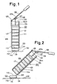
- Fig.1 to Fig.6 relate to a first embodiment of the present invention.
- a part having a flat surface of an article is protected by a masking member.
- a flat type masking member(111) has a smooth and flat surface on the upper side(113) and an adhesive layer(114) is formed on the lower side(112) and a plural number of said masking members(111) are placed one upon another to form a group of masking members(117). In said group of masking members(117), said masking members (111) are mutually adhered by said adhesive layer(114) thereof.
- a masking tool(120) comprises a cylinder(121) having an inlet(122) at one end and on outlet(123) at the other end, a friction sheet(129) attached to the inside of said cylinder(121), and a piston(124) as a transporting means.
- Said piston(124) is inserted into said cylinder (121) from said inlet(122) thereof and a handle(126) is connected to the piston rod(124A) of said piston(124) wherein a pin(128) of said piston rod(124A) is inserted in a groove(127A ) of a bracket(127)of said handle(126).
- Said group of masking members(117) is put into said cylinder(121) of said masking tool(120) and said adhesive layer(114) of each masking member(111) faces in a direction to the outlet(123) of said cylinder(121) and said piston(124) of said masking tool(120) contacts with the upper side(113) of one of said masking members (111) which is located in the uppermost position of said group of masking members(117).
- Said masking members(111) of said group (117) are successively transported from the inlet(122) to the outlet(123) in said cylinder(121) by operation of said piston(124) by said handle(126).
- Said handle may be operated by hand, oil pressure, electromagnetic means, and the like.
- one of said masking members(111) located in the lowest position of said group (117) is pushed out from the outlet(123) of said cylinder(121) by operation of said piston(124) and attached to a part (131) having a flat surface of an article(130) by said adhesive layer(114) of said masking member(111) as shown in Fig.1.
- said masking member(111) is sepa rated from said group (117) in said cylinder(121) of said masking tool(120) as shown in Fig.2.
- said masking tool(120) is operated by a robot and in this case, said masking members(111) are automatically attached to said part(131) without the necessity of a worker's hands.
- said piston (124) may be directly operated by a pressure oil cylinder, an electromagnetic cylinder, and the like instead of said handle(126).
- Said masking member(111) is made of a material, such as a plastic or a rubber such as polystyrene, polyethylene, polypropylene, ethylene-propylene copolymer, polyvinylchloride, polyvinylidene chloride, polymethacrylate, styrene-butadiene copolymer, acrylonitrile-butadiene copolymer, polybutadine polyisoprene, polyisobutylene, polychloroprene, isoprene-isobutylene copolymer, natural rubber, polyurethane, melamine resin, urea resin, phenol resin, epoxy resin and the like; foams of said plastic or said rybber; a mixture of said plastic or said rubber with a filler such as calcium carbonate, talc, bentonite, fly ash, blast furnace slag, and the like; a fiber material such as thermoplastic resin -impregnated
- a material having small gas permeability should be selected as the material of said masking member (111) and the upper side of said masking member(111) should have a smooth flat part.
- a material having a large gas permeability such as foams of plastic or rubber, a fiber material are also usable as a material of said masking member(111) if a material having a small gas permeability such as a plastic film, a metal film is laminated on said material.
- the peeling strength between said masking member(111) and said part(131) of said article (130) be adjusted larger than the peeling strength between a pair of said masking members(111), (111) mutually in contact.
- the contact area between said masking member(111) and said part(131) should be adjusted larger than the contact area between a pair of said masking members(111),(111) mutually in contact, or the bonding strength between said masking member(111) and said part(131) should be adjusted larger than the bonding strength between a pair of said masking members(111),(111) mutually in contact.
- said adhesive layer(114A) is fully formed on the lower side(112A) of said masking member(111A) and a dent(115A ) having a smooth and flat surface(116A) in the bottom thereof is formed on the upper side(113A) of said masking member (111A) as shown in Fig.3 A, or said adhesive layer(114B) is partially formed on the circumference of the lower side(112B) of said masking member(111B) and a smooth and flat surface is fully formed on the upper side(113B) wherein four projections( 115B) are respectively formed on the four corners of said upper side(113B) as shown in Fig.3 B and Fig.3C, or said adhesive layer(114C) is fully formed on the lower side(112C) of said masking member(111C) and a projection(
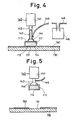
- said masking member(111) is attached to said part(131) of said article(130) by said adhesive layer(114) formed on the lower side(112) of said masking member(111), and after this, a paint such as a polyvinylchloride-sol, a urethane resin, an asphalt, a rubber-asphalt mixture, a tar-urethane mixture and the like is coated on the surface of said article to form a coating layer(150) as shown in Fig.4. After said coating, said masking member(111) is removed from said part(131).
- a paint such as a polyvinylchloride-sol, a urethane resin, an asphalt, a rubber-asphalt mixture, a tar-urethane mixture and the like is coated on the surface of said article to form a coating layer(150) as shown in Fig.4. After said coating, said masking member(111) is removed from said part(131).
- a removing tool(140) as shown in Fig.4 is used.
- Said removing tool(140) comprises an oil pressure cylinder(141), a pipe(143) attached at the end of the piston rod(142) of said oil pressure cylinder(141), a sucker (144) attached at the end of said pipe(143), and a vacuum tube(145) in which a trap(146) intermediates.
- Said sucker(144) is made of a rubber, a plastic, a metal, and the like.
- Said sucker(144) of said removing tool (140) contacts with the upper side(113) of said masking member(111) and said masking member(111) is sucked up by said sucker(144).
- Said coating layer(150) is sucked into said vacuum tube(145) through said sucker(144) and said pipe(143) and collected in said trap(146).
- said piston rod(142) is lifted by the operation of said oil pressure cylinder(141) to peel said masking member(111) from said part(131) of said article (130) as shown in Fig.5.
- Said masking member(111) may be removed from said sucker(144) of said removing tool (140) by opening said vacuum tube(145) to the atmosphere or by putting air into said vacuum tube(145).
- Fig.6 A and Fig.6 B show other embodiments of said masking member(111) used to protect a part having a flat surface of an article in the first embodiment.
- a vessel type masking member(111D) has a flange(112D) at the open end and an adhesive layer(114D) is formed on said flange(112D). Further said masking member(111D) has a smooth and flat surface(115D) on the outside of the bottom(113D).
- Said masking member(111) is attached to said part (131) having a flat surface of said article by said adhesive layer(114) the same as for said masking member (111) shown in Fig.3 A,B,C,D and peeled from said part (131) by said removing tool(140) by sucking said surface (115D) of the outside of the bottom(113D) of said masking member(111D).
- a vessel type masking member(111E) has a flange(112E) at the open end and an adhesive layer(114E) is formed on the outside of the bottom(113E) wherein a smooth and flat surface(115E) is formed on the inside of the bottom(113E).
- Said masking member(111E) is attached to said part(131) of said article by said adhesive layer(114) the same as for said masking member(111) shown in Fig.3 A,B,C,D and Fig.6 A and peeled from said part(131) by said removing tool(140) by sucking said surface(115E) at the inside of the bottom(113E) of said masking member(111E).
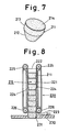
- Fig.7 to Fig.9 relate to a second embodiment of the present invention.
- a hole in an article is protected by a masking member.
- a plug type masking member(211) consists of a tapered part(212) and cylinderical part(213) and the upper side of said cylinderical part(213) forms a smooth and flat surface(214).
- a masking tool(220) of this embodiment comprises a cylinder(221) having an inlet(222) at one end and an outlet(223) at the other end, and a pair of endless belts(224),(224) acting as a transporting means.
- Each of said endless belts(224),(224) is suspended on a pair of rollers(225),(226) wherein one set of said rollers (225), is rotatably attached to the inlet(222) of said cylinder(221) and the other set of said rollers(226) are rotatably attached to the outlet(223) of said cylinder(221).
- Said endless belts(224),(224) are respectively made of a friction material such as a rubber, a cloth having a flocking layer, and the like.
- a plural number of said masking members(221) are placed one upon another to form a group of masking members(215) and said group of masking members(215) is put into said cylinder(221) of said masking tool(220) wherein said group of masking members(215) is trapped between a pair of said endless belts(224),(224) in said cylinder(221) of said masking tool(220).
- Said masking member(221) of said group (215) are successively transported from the inlet(222) to the outlet(223) in said cylinder(221) by driving said rollers(225),(226) by a driving means such as a motor and the like to insert said masking members(211) into a hole(231) in an article(230) as shown in Fig.8.
- a surface treatment layer(250) is formed on the surface of said article(230)
- said masking member(221) is removed from said hole(231) by using said removing tool(140) of the first embodiment by sucking said surface(214) of said masking member(211).
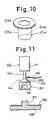
- Fig.10 shows another embodiment of said masking member used to protect a hole in an article.
- a masking member(211A) consists of a vessel type inserting part(212A) and a flange(213A) wherein a smooth and flat surface(214A) is formed on the inside of the bottom of said inserting part(212A). Said masking member(211A) is attached in said hole(231) of said article(230) by inserting said inserting part(212A) thereof and removing it from said hole(231) by said removing tool(140) by sucking said surface(214A) of said masking member(211).
- Fig.11 and Fig.12 relate to a third embodiment of the present invention.
- a projection of an article is protected by a masking member.
- a cap type masking member(311) having a hole(312) and a smooth and flat surface(313) on the upper side thereof is attached over a projection(331) of an article(330) by inserting said projection(331) into said hole(312) of said masking member(311) and removing it from said projection(331) by said removing tool(140) by sucking said surface(313) of said masking member(311) after a surface treatment layer(350) is formed on said article(330).
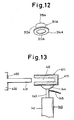
- Fig.12 shows another embodiment of said masking member used to protect a hole in an article and said masking member(311A) consists of a vessel type cap part (312A) having a hole(313A) and a flange(314A) wherein a smooth and flat surface(315A) is formed on the outside of the bottom of said cap part(312A).
- Said masking member(311A) is attached over said projection(331) of said article(330) by inserting said projection into said hole(313A) of said cap part(312A) thereof and is removed from said projection(331) by said removing tool (140) by sucking said surface(315A) of said masking member(311A).
- Fig.13 relates to a fourth embodiment.
- a flat part(431) of an article(430) is protected by a clip type masking member(411) having a slit(412) wherein a smooth and flat surface(413) is formed on the outside of said masking member(411).
- Said masking member(411) is attached onto said flat part(431) of said article(430) by inserting said flat part(431) of said article(430) and is removed from said flat part(431) by said removing tool(140) by sucking said surface(413) of said masking member(411).
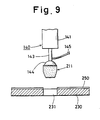
- Fig.14 and Fig.15 relate to a fifth embodiment.
- a plural number of said masking members(111) of the first embodiment are removed by a removing tool(240).
- said removing tool(240) comprises a vacuum pipe(242) connected to a vacuum pump(241), a plural number of branch pipes(243) connected to said vacuum pipe(242), a plural number of suckers(244) connected respectively to the lower end of said branch pipes(243), and a pair of valves(245), (246) arranged at both ends of said vacuum pipe(242).
- a plural number of said masking members (111) are respectively sucked up by a plural number of said suckers(244) of said removing tool(240) as shown in Fig.14 and said removing tool(240) is lifted to peel a plural number of said masking members(111) from a plural number of said part(131) at one time as shown in Fig.15.
- said valve(145) is shut and said valve(146) is opened and said vacuum pump (141) is operated.
- said valve(145) is opened. If desired, said valve(146) is shut and/or said vacuum pump(141) is stopped. Further, to suck a plural number of said masking members(111), a pair of said valves(145),(146) are opened and said vacuum pump(141) is operated, thus air passes through said vacuum pipe(142) and a plural number of said masking member(111) are also sucked up by a plural number of said suckers(144).
- Fig.16 relates to a sixth embodiment.
- a plural number of said masking members(211) of the second embodiment are removed at one time from a plural number of said holes(231) of said article(230), on which a surface treatment layer(250) is formed, by said removing tool(240).
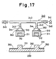
- Fig.17 relates to a seventh embodiment.
- a plural number of said masking members(311) of the third embodiment are removed at one time from a plural number of said projection(331) of said article (330), on which a surface treatment layer(350) is formed, by said removing tool(240).
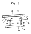
- Fig.18 relates to an eighth embodiment.
- said masking member(111) having a large capacity is removed by a pair of said suckers(244) of said removing tool(240) from a part of an article.
Landscapes
- Details Or Accessories Of Spraying Plant Or Apparatus (AREA)
- Application Of Or Painting With Fluid Materials (AREA)
- Thin Film Transistor (AREA)
- Liquid Crystal (AREA)
Applications Claiming Priority (6)
| Application Number | Priority Date | Filing Date | Title |
|---|---|---|---|
| JP14136089A JPH038473A (ja) | 1989-06-02 | 1989-06-02 | 表面処理方法 |
| JP141360/89 | 1989-06-02 | ||
| JP21686189 | 1989-08-22 | ||
| JP216861/89 | 1989-08-22 | ||
| JP291962/89 | 1989-11-08 | ||
| JP29196289A JPH03170692A (ja) | 1989-08-22 | 1989-11-08 | 表面処理方法 |
Publications (2)
| Publication Number | Publication Date |
|---|---|
| EP0401043A2 true EP0401043A2 (de) | 1990-12-05 |
| EP0401043A3 EP0401043A3 (de) | 1991-08-14 |
Family
ID=27318229
Family Applications (1)
| Application Number | Title | Priority Date | Filing Date |
|---|---|---|---|
| EP19900306014 Withdrawn EP0401043A3 (de) | 1989-06-02 | 1990-06-01 | Verfahren zur Oberflächenbehandlung |
Country Status (4)
| Country | Link |
|---|---|
| US (1) | US5091220A (de) |
| EP (1) | EP0401043A3 (de) |
| KR (1) | KR0130197B1 (de) |
| CA (1) | CA2017893A1 (de) |
Cited By (3)
| Publication number | Priority date | Publication date | Assignee | Title |
|---|---|---|---|---|
| EP0604691A1 (de) * | 1992-12-31 | 1994-07-06 | Nagoya Oilchemical Co., Ltd. | Verfahren und Vorrichtung zur Befestigung eines Abdeckelementes |
| DE19701194C1 (de) * | 1997-01-15 | 1998-03-12 | Stahlschmidt & Maiworm | Verfahren und Vorrichtung zum Abdecken von Befestigungslöchern und Wiederfreilegen derselben bei der Herstellung von Rädern für Kraftfahrzeuge |
| EP1127945A3 (de) * | 2000-02-17 | 2004-08-18 | General Electric Company | Verfahren und Vorrichtung zum Kugelstrahlen |
Families Citing this family (7)
| Publication number | Priority date | Publication date | Assignee | Title |
|---|---|---|---|---|
| KR100495804B1 (ko) * | 1997-12-23 | 2005-09-15 | 삼성전자주식회사 | 액정표시장치용박막트랜지스터기판및그제조방법 |
| US7022187B2 (en) * | 2002-03-28 | 2006-04-04 | Everett Ray Stockton | Insert mask for masking ceiling or wall fixtures |
| DE10359802B3 (de) * | 2003-12-19 | 2005-03-31 | Federal-Mogul Burscheid Gmbh | Kolbenring sowie Verfahren zur Herstellung desselben |
| US6967041B1 (en) * | 2004-02-11 | 2005-11-22 | Valmont Industries, Inc. | Method of masking areas of an object during galvanizing |
| JP2007125448A (ja) * | 2005-11-01 | 2007-05-24 | Nagoya Oil Chem Co Ltd | マスキング材 |
| US7829003B2 (en) * | 2006-04-20 | 2010-11-09 | Basf Corporation | Method of making an article |
| TWI458557B (zh) * | 2009-11-26 | 2014-11-01 | Hon Hai Prec Ind Co Ltd | 噴塗遮蔽結構及採用該結構之噴塗遮蔽方法 |
Family Cites Families (9)
| Publication number | Priority date | Publication date | Assignee | Title |
|---|---|---|---|---|
| US2290472A (en) * | 1940-07-17 | 1942-07-21 | Joseph V Hendrick | Painter's masking shield |
| US2286473A (en) * | 1940-07-29 | 1942-06-16 | Duggan James Edward | Paint mask structure |
| US2363842A (en) * | 1942-09-08 | 1944-11-28 | Duggan James Edward | Mask structure |
| US2672122A (en) * | 1952-08-04 | 1954-03-16 | Emil J Kupec | Surface masking shield for painters |
| US4835026A (en) * | 1985-06-27 | 1989-05-30 | Nagoya Oilchemical Co., Ltd. | Masking member |
| GB2189768B (en) * | 1986-05-01 | 1990-07-11 | Avery International Corp | Pressure sensitive labels in block form |
| JP2514173B2 (ja) * | 1986-06-09 | 1996-07-10 | 名古屋油化株式会社 | 自動車床裏の防錆防音防振処理方法 |
| JPH0525748Y2 (de) * | 1986-08-06 | 1993-06-29 | ||
| FR2605617B1 (fr) * | 1986-10-23 | 1989-05-19 | Imcarvau | Machine pour l'application automatique de feuilles autocollantes sur des articles |
-
1990
- 1990-05-30 CA CA002017893A patent/CA2017893A1/en not_active Abandoned
- 1990-06-01 US US07/532,017 patent/US5091220A/en not_active Expired - Fee Related
- 1990-06-01 EP EP19900306014 patent/EP0401043A3/de not_active Withdrawn
- 1990-06-02 KR KR1019900008514A patent/KR0130197B1/ko not_active Expired - Fee Related
Cited By (4)
| Publication number | Priority date | Publication date | Assignee | Title |
|---|---|---|---|---|
| EP0604691A1 (de) * | 1992-12-31 | 1994-07-06 | Nagoya Oilchemical Co., Ltd. | Verfahren und Vorrichtung zur Befestigung eines Abdeckelementes |
| DE19701194C1 (de) * | 1997-01-15 | 1998-03-12 | Stahlschmidt & Maiworm | Verfahren und Vorrichtung zum Abdecken von Befestigungslöchern und Wiederfreilegen derselben bei der Herstellung von Rädern für Kraftfahrzeuge |
| EP0853982A3 (de) * | 1997-01-15 | 2001-12-12 | STAHLSCHMIDT & MAIWORM GmbH | Verfahren und Vorrichtung zum Abdecken von Befestigungslöchern an einem Rad |
| EP1127945A3 (de) * | 2000-02-17 | 2004-08-18 | General Electric Company | Verfahren und Vorrichtung zum Kugelstrahlen |
Also Published As
| Publication number | Publication date |
|---|---|
| KR0130197B1 (ko) | 1998-04-06 |
| CA2017893A1 (en) | 1990-12-02 |
| US5091220A (en) | 1992-02-25 |
| KR910000242A (ko) | 1991-01-29 |
| EP0401043A3 (de) | 1991-08-14 |
Similar Documents
| Publication | Publication Date | Title |
|---|---|---|
| EP0401043A2 (de) | Verfahren zur Oberflächenbehandlung | |
| US6581641B2 (en) | One-way valve for use with vacuum pump | |
| WO2001066419A3 (en) | Inflatable packing and inflation apparatus | |
| CA2209826A1 (en) | Flexible pressure vessels for and method of transporting hazardous materials | |
| CA2151324A1 (en) | Magnetic material attracting/releasing control method making use of a pipette device and various types of clinical inspection apparatus using the method | |
| CA2233127A1 (en) | Method and apparatus for separating composite member using fluid | |
| WO1991016140A1 (en) | Masking material | |
| JPH07156089A (ja) | 材料の捕捉および搬送装置 | |
| US5193716A (en) | Masking method | |
| JPH058768A (ja) | 壁面剥離ロボツト | |
| EP0401042B1 (de) | Gruppe von Maskierelementen und Verfahren zu ihrer Befestigung | |
| CA2062960A1 (en) | Method for masking | |
| EP0406002A2 (de) | Verfahren zur Oberflächenbehandlung | |
| CA2057887A1 (en) | Sucker | |
| EP0509100A1 (de) | Maskierungsmaterial | |
| EP1072800A3 (de) | Absaugvorrichtung und diese verwendende Trennvorrichtung | |
| EP0472737A1 (de) | Sauggreifer | |
| EP0472732A1 (de) | Verfahren zum anbringen oder entfernen eines abdeckmaterials | |
| JPH03170692A (ja) | 表面処理方法 | |
| JP3711195B2 (ja) | 吸着エレメントおよび物品吸着装置 | |
| EP0483377A1 (de) | Abdeckmaske | |
| EP1190846A3 (de) | Verbundmaterialien auf Kautschukbasis und Gummi-Artikel damit | |
| JP4321695B2 (ja) | 内袋付き箱型容器及びその製造方法 | |
| JP2561613B2 (ja) | 薄板の堆積層間の接着捌き方法およびその装置 | |
| EP0604691A1 (de) | Verfahren und Vorrichtung zur Befestigung eines Abdeckelementes |
Legal Events
| Date | Code | Title | Description |
|---|---|---|---|
| PUAI | Public reference made under article 153(3) epc to a published international application that has entered the european phase |
Free format text: ORIGINAL CODE: 0009012 |
|
| AK | Designated contracting states |
Kind code of ref document: A2 Designated state(s): DE FR GB IT SE |
|
| PUAL | Search report despatched |
Free format text: ORIGINAL CODE: 0009013 |
|
| AK | Designated contracting states |
Kind code of ref document: A3 Designated state(s): DE FR GB IT SE |
|
| RHK1 | Main classification (correction) |
Ipc: B05C 21/00 |
|
| 17P | Request for examination filed |
Effective date: 19911106 |
|
| 17Q | First examination report despatched |
Effective date: 19930827 |
|
| STAA | Information on the status of an ep patent application or granted ep patent |
Free format text: STATUS: THE APPLICATION IS DEEMED TO BE WITHDRAWN |
|
| 18D | Application deemed to be withdrawn |
Effective date: 19950531 |