EP0401237B1 - Heizungsanlage für gebäude mit warmem wasser - Google Patents
Heizungsanlage für gebäude mit warmem wasser Download PDFInfo
- Publication number
- EP0401237B1 EP0401237B1 EP89902180A EP89902180A EP0401237B1 EP 0401237 B1 EP0401237 B1 EP 0401237B1 EP 89902180 A EP89902180 A EP 89902180A EP 89902180 A EP89902180 A EP 89902180A EP 0401237 B1 EP0401237 B1 EP 0401237B1
- Authority
- EP
- European Patent Office
- Prior art keywords
- pipes
- pipe
- elements
- shell
- designed
- Prior art date
- Legal status (The legal status is an assumption and is not a legal conclusion. Google has not performed a legal analysis and makes no representation as to the accuracy of the status listed.)
- Expired - Lifetime
Links
Images


Classifications
-
- F—MECHANICAL ENGINEERING; LIGHTING; HEATING; WEAPONS; BLASTING
- F24—HEATING; RANGES; VENTILATING
- F24D—DOMESTIC- OR SPACE-HEATING SYSTEMS, e.g. CENTRAL HEATING SYSTEMS; DOMESTIC HOT-WATER SUPPLY SYSTEMS; ELEMENTS OR COMPONENTS THEREFOR
- F24D19/00—Details
- F24D19/0002—Means for connecting central heating radiators to circulation pipes
- F24D19/0009—In a two pipe system
-
- F—MECHANICAL ENGINEERING; LIGHTING; HEATING; WEAPONS; BLASTING
- F24—HEATING; RANGES; VENTILATING
- F24D—DOMESTIC- OR SPACE-HEATING SYSTEMS, e.g. CENTRAL HEATING SYSTEMS; DOMESTIC HOT-WATER SUPPLY SYSTEMS; ELEMENTS OR COMPONENTS THEREFOR
- F24D3/00—Hot-water central heating systems
- F24D3/10—Feed-line arrangements, e.g. providing for heat-accumulator tanks, expansion tanks ; Hydraulic components of a central heating system
- F24D3/1058—Feed-line arrangements, e.g. providing for heat-accumulator tanks, expansion tanks ; Hydraulic components of a central heating system disposition of pipes and pipe connections
- F24D3/1066—Distributors for heating liquids
- F24D3/1075—Built up from modules
Definitions
- the present invention relates to a heat installation for buildings using water as a heat transmitting medium, and is set forth in greater detail in the preamble of patent claim 1.
- Such conventional heat installations comprise loosely layed visible piping or piping accommodated in walls and floors respectively. Said installations are designed throughout either as one- or as two-pipe-systems. In all of the cases the installation has been performed by artisans with a manual individual pipe laying and assembly operation, which is very expensive and time-consuming. In case such a system is to be installed in already finished houses, usually it is required that the floors and walls be torn open for an invisible pipe laying, or if the pipe laying is to be visible, said pipes will constitute a strongly disturbing factor and also usually will emit heat in places where heat is not required, which to some extent is true as regards pipe laying in walls and floors, in which the heat insulation is unsatisfactory.
- Invisible pipe laying may involve risk of leakage, which is hard to discover, with severe damages as a result, when leakage has been discovered after usually an extended period of time, and the development of mould, rot and rust.
- Irrespective of whether an installation is done in connection with the erection of a building or in an already finished building painters, carpenters, floor-layers etc. have so far been required to be able to complete their work or else they were required to perform additional work, when the installation contractors have completed their work.
- the problem whether to select an one-pipe- or a two-pipe-system has also often been difficult to solve.
- One of the two systems may have been suitable for e.g. one specific module or building element, while the other one had been suitable for other modules.
- the object of the present invention is to suggest an improved heat installation, in which water is used as a heat transmission medium and which avoids the drawbacks mentioned above and promotes the state of the art in this field in various respects.
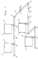
- Fig. 1 of the accompanying drawings to lay one branch along one portion of a building, while another branch provides another portion of the building with heat.
- said one branch can be designed as an one-pipe-system and the other branch as a two-pipe-system, and in this way different heating requirements can be met in an optimal manner.
- the production of the various components, which the system includes, can be done in simple, fast and inexpensive ways due to a large scale production, e.g. through casting or injecting molding of metallic and plastic materials respectively, starting with uniform modules for radiator connection elements, which subsequently can be easily and specifically adapted for e.g. one- or two-pipe-operation and having varying choking/heat emission capacities respectively.
- radiators having an arbitrary size/heat emission capacity in arbitrarily selected areas and, if that is required, at the same time select an adequate circulation of the heat medium through the radiator.
- This installation can easily be designed to smoothly and in principle without problems be passed by a door opening in a way that is set forth in the following description and the accompanying drawings, such an installation section preferably being designed as a threshold. It is then possible, in case this is required in a particular case, to without problems obtain a reversal of the pipes, i.e. to let the forward and return pipes change places, the upper pipe on one side of the door opening becoming the bottom pipe on the other side. All the components in the installation can be designed to emit heat in an adequate manner, i.e.
- a main connection element 1 is shown, which in a way known per se is designed to be connected to main pipings (not shown) to and from e.g. a central heater (not shown) and which is shown in more detail in Fig. 2.
- connection elements 2 are shown in more detail and in Fig. 4 inner corner elements 3 and outer corner elements 4 respectively are shown.
- Threshold transition elements 5 and 7 are mirror-symmetrically alike.
- Element 5 is shown in detail in Fig. 5.
- a threshold 6 is disposed between such threshold transition elements.
- a radiator connection element 8 is shown in detail in Fig. 6. Terminal parts 9 for blind loop ends are shown and in Fig. 7 a joint element 10 is shown in detail, while in Fig. 1 radiators 11 are shown, which can be conventional hot water radiators having conventional radiator valves 12.
- the heat installation shown in Fig. 1 is provided with two blind branches, it being easy to design each branch, thanks to the characterizing features of the present invention, according to individual needs at any time for an one-pipe-operation or a two-pipe-operation. It is easy to design e.g. one of the branches for one-pipe-operation and the other for two-pipe-operation, there being no need to make any exterior alterations. It is also possible, at any time, to add to the branches, i.e. extend them and/or mutually connect their ends. Also, it is easy to later on connect additional radiators and to remove existing radiators respectively from the system.
- a heat installation according to the invention advantageously can be designed as a basic module system or building element system, selling the various components advantageously being done in self-service outlets and an installation subsequently being done by the buyer himself, e.g. a home or an apartment owner. It is true that the majority of the components can be delivered in one single standard design as to dimensions, but it is easy to provide connection elements 2 and thresholds 6 in various lengths, it thereby being easy and simple to accommodate them to different installation dimensions and designs, particularly because the exact location of the various components per se easily can be adjusted within certain limits thanks to the insertion principle and the relative displaceability together with maintained functions for the rest which result from it.
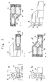
- Main connection element 1 shown in Fig. 2 comprises an arbitrarily designed strip- or block-shaped shell 13, which can be solid or hollow and be made of a plastic and/or metallic material having a front or room side 14 and a rear or connection side 15, from which connection pieces 16,17 project, which are placed on different levels and which are connected at right angles to one return pipe and one forward pipe respectively, namely pipe 18 and pipe 19 respectively, which extend through the main connection element in its longitudinal direction.
- Pipes 18,19 are usually open in both directions, but in case just one branch is to issue from said main connection element, one of the end openings of pipes 18,19 can be closed, e.g. plugged up.
- Front side 14 and upper side 20 of the main connection element can be decoratively designed in an arbitrary way, suitably in the same way and with the same profile dimensions as the following components, which are included in the installation.
- Pipe 18 is of course the feed pipe for hot water and pipe 19 the return pipe for colder water.
- the upper pipe is e.g. the feed pipe.
- Pieces 16,17 advantageously can comprise essentially tubular through elements (see Fig. 2a), which extend through transverse cuts in shell 13 and engage with closed ends having flanges 21 in a somewhat broader recess 22 on the room-side of the shell, nipples 23 and 24 respectively being secured on ends, which project from the rear side of said pieces and e.g.
- Connection element 2 shown in Fig. 3, comprises a shell 25 comprising e.g. a closed external housing 26, which accommodates ducts 27,28, one disposed above the other, which are designed to function as a return pipe and a forward pipe respectively and which project beyond the two ends of the shell in its longitudinal direction, e.g. different distances at the two sides, as shown in Fig. 3 b, at least as regards elements adjacent a joint element to be described subsequently.
- Ducts 27,28 can be integral with shell 25 by means of bridge portions 29 according to Fig. 3a.
- said shell can be provided with central transverse control elements 30 designed as holes and/or casings for screws or the like, by means of which said elements can be fastened to e.g. a wall 81.
- connection element can be made all of a piece, of a plastic and/or metallic material, e.g. aluminum, and remaining cavities can advantageously be filled with an insulating material 31 in a way known per se as regards the method.
- ducts 27,28 according to Fig. 3a can be designed solely as control elements, which possibly are not through elements in their longitudinal direction and/or their circumferential direction, for separately introduced ducts, which possibly subsequently can be fastened to the shells, if that is desirable.
- connection elements are provided with circumferential external bevellings 82.
- FIGs. 4a and 4c an inner corner element 32 is shown, legs 33,34 of which suitably having the same external profile as said connection elements and said main connection element.
- An outer corner element 35 according to Figs. 4b and 4d is designed in a similar fashion having legs 36 and 37 and the only difference between the two elements is that the room side, i.e. the possibly decorated side, in one of the cases is an inner corner and in the other case an outer corner.
- pipes 18,19 are disposed one above the other and their ends are provided with circumferential grooves 38, in which O-rings or the like 39 are introduced.
- corner elements are connected in a simple way to adjacent connection elements, the projecting duct ends of the latter being inserted in legs at least such a distance, that O-rings or the like 39 are passed and in this way are expanded and consequently seal.
- Said corner elements can also be made in one piece of a plastic and/or a metallic material. They can be made hollow according to Fig. 3a or possibly solid.
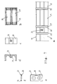
- Threshold transition element 5 shown in Fig. 5, corresponds mirror-symmetrically to threshold transition element 7, and thus the latter will not be shown or described in more detail. It is shown that element 5 has an upended portion 40, similar to the components described above and which changes into a horizontal portion 41. The latter portion suitably is, as regards the external profile, similar to threshold 6, and in this way an adaptation to various threshold profiles can easily be done. It is shown in the various views in Fig. 5 that upper pipe 19 changes via an obliquely downwardly directed passage 42 into a lower extension of the same pipe, while lower pipe 18 via a passage 43, in an obliquely lateral direction, changes into a laterally shifted extension of the same pipe. Fig.
- 5e shows that the two pipes 18,19 are disposed within the horizontal threshold transition portion 41 adjacent each other in the same horizontal plane.
- the same pipe orientation is used within threshold 6, not shown in detail, which then is connected to the mirror-symmetrically designed threshold transition element 7, in which pipe 19 again being disposed on top within portion 40 or possibly, if it is desirable in a special case, at the bottom, which is easily done e.g. if passage 42 does not extend in a vertical plane obliquely downwardly but obliquely downwardly in a lateral direction in either element 5 or 7, while lower pipe 18 continues straight ahead, in which way a reversal can be attained, which however normally probably is not required.
- the end openings of pipes 18,19 are, in the same way as is shown in Fig. 4, provided with internal grooves 44 and O-rings or the like 45 introduced in said grooves. Also, in required places possibly screwed plugs 46,47 can be used in order to render possible a chip removal machining operation or the like.
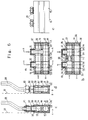
- Radiator connection element 8 shown in Fig. 6, is mainly similar in its design to the above-described elements and comprises a shell 48, which accommodates pipes 18,19, the end areas of which, in a way which corresponds to the above-described elements, are provided with internal grooves 49 and O-rings or the like 50 introduced in said grooves.
- connection elements 2 can be sealingly connected in the two directions, and a longitudinal adjustment can thus be obtained.
- two similar vertical cylindrical cuts 51 are disposed in shell 48, at a distance in a horizontal direction from each other and e.g. having a step-shaped expansion element 52 at their lower ends and a similar constriction element 53 at their upper ends, from which said cut with its smallest diameter extends outwardly through the upper side of shell 48.
- each cut 51 an insert 54 or 55 is introduced.
- Said inserts have a common principal design, namely a cylindrical body, which essentially fills the respective cuts and has a lower flange 56 and 57 respectively and an upper step-shaped end 58 and 59 respectively as well as connection pieces 60 and 61 respectively, which project through the upper cut opening.
- On said pieces preferably provided with external threads, suitably nipples 62 can be screwed, which allow, via seals or the like 63, a sealing against said shell and said insert as well as a sealed engagement of said flanges 56,57 against the adjacent portion of said cut, preferably with intermediate seals or the like (not shown).
- Connection pipes 64 to a radiator 11 can then be connected to nipples 62 by means of nuts 65 in a way known per se.
- Inserts 54,55 are provided with openings, which correspond to pipes 18 and 19 respectively.
- insert 54 suitably there is a full equivalence
- insert 55 a direct connection between the radiator and pipe 18 via a closer casing-shaped passage 66 is intended as regards one of said radiator connections 64.
- the radiator connection element according to Fig. 6 a which is designed for two-pipe-systems, in which one of said radiator connections 64 is entirely connected to pipe 19, while the other radiator connection 64 is entirely connected to pipe 18, pipe 19 being extended round the closer casing-shaped portion 66, which is shown in Fig. 6a and d.
- insert 55 which are shown in Fig. 6a and d.
- the material in shell 8 possibly can also be reduced around casing-shaped portion 66, i.e. within the area of upper pipe 19 around each cut 51, if that is required.
- Said inserts are around their waist suitably provided with circumferential grooves 87 and O-rings or the like 88 introduced into said grooves.
- Fig. 6b The design according to Fig. 6b is used for one-pipe-operation, two similarly designed inserts 54 suitably being introduced into cuts 51, while the section of pipe 19 and/or possibly pipe 18 between said inserts is provided with a choke element 68, which it is easy to introduce in the respective pipes from either end, which choke element is shaped like a casing, suitably provided with recessed ends and en external circumferential O-ring 69, introduced into a groove 70, and suitably in this way simultaneously an advantageous friction locking can be obtained.
- This choke element has a passage with a reduced diameter and thus the first radiator connection, seen in the flow direction of the heat medium, is subjected to a higher pressure and consequently can function as an inlet, while the second radiator connection, subjected to a lower pressure, functions as an outlet.
- a series of radiator connection elements a choking according to e.g. a falling or rising scale can be obtained.
- Cuts 51 and/or inserts 54,55 can be provided with rotation-preventing location notches, in order to position the various pipe sections exactly on one line. To prevent a rotation in this way is a method already known per se and thus such notches are not shown in detail.
- a joint element is shown, generally designated 10, which possibly is needed between two adjacent connection elements.
- This element is provided with a shell 71 having pipes, grooves and O-ring or the like according to the design illustrated above, and in order to accommodate e.g. longer projecting pipes a distance element 72 having a central recessed bore or the like 73, designed to introduce a mounting screw, not shown, can be used.
- the material around bore 73 can be extended inwardly in order to form a location notch 74 designed to hold said pipes.
- the latter may in said joint elements, also as regards joint elements between other module elements 1-10, be surrounded by cover elements 75 having a wall 76, which surrounds said pipes, and an external joint lip 77, which covers said joint elements outwardly.
- terminal parts 9 are shown, namely one terminal part for an one-pipe-system in Fig. 8a and one terminal part for a two-pipe-system in Fig. 8b.
- the difference is that within the terminal part for an one-pipe-system the two pipes 18,19 are connected to each other through an end passage 78, while instead of such a passage a diaphragm 79 is used in the terminal part for a two-pipe-system.
- the only difference is that in a two-pipe-system already in the first fed radiator the return water enters into the return piping, while a true return piping not starts until in the terminal part as regards a one-pipe-system.
- the present invention is not limited to the embodiments described above and shown in the accompanying drawings. All of the components can of course be provided with e.g. a covering shell of some kind of fine wood or of any other arbitrarily selected material and configuration, and possibly quick-locking means designed in a way known per se can be used. Also, it is possible, according to the need, to make the various modules more or less heat-insulating, which has been stated above.
- the modules advantageously can be provided with at least one extra through cavity in their longitudinal direction, e.g. in the form of a third and a fourth pipe or piping respectively, through which cavities e.g. cooled or heated air can be transported or which can be used for wiring of e.g. electrical, tele- and/or communication wires etc.
Landscapes
- Engineering & Computer Science (AREA)
- Physics & Mathematics (AREA)
- Thermal Sciences (AREA)
- Chemical & Material Sciences (AREA)
- Combustion & Propulsion (AREA)
- Mechanical Engineering (AREA)
- General Engineering & Computer Science (AREA)
- Steam Or Hot-Water Central Heating Systems (AREA)
- Thermal Insulation (AREA)
Claims (11)
- Heizungsanlage für Gebäude mit Wasser als Wärmeübertragungsmedium und mit zwei Rohrleitungen (18, 19), eine von welchen eine Vorlauf- und die andere eine Rücklaufleitung ist, an welche Rohrleitungen Heizkörper (11) angeschlossen sind, welche Anlage als Modul- oder Baukastensystem ausgeführt ist, welches verschieden ausgeführte leisten- und blockförmige Bauteile (1-10) umfasst, die ineinander einsteckbar sind, und bei denen genannte Vorlauf- und Rücklaufleitungen integrierte Teile, z.B. an genannten Teilen befestigt sind, wobei für genannten Heizkörperanschluss speziell ausgeführte Bauteile (8) vorhanden sind, dadurch gekennzeichnet, dass genannte Vorlauf- und Rücklaufleitungen (18, 19) direkt übereinander in genannten Anschlussteilen (8) wie auch in der Mehrzahl der anderen Bauteile angeordnet sind, und- dass zylindrische Durchbrüche durch genannte Anschlussteile vorgesehen sind, wobei genannte Durchbrüche innerhalb der Ebene genannter Leitungen angeordnet sind und sich rechtwinklig hierzu erstrecken, und- dass in genannte Durchbrüche Einsätze (54, 55) eingesetzt sind;- dass ein erster Einsatz eine direkte Verbindung zwischen dem Heizkörper und der unteren genannter Leitungen, welche bevorzugt die Rücklaufleitung ist, über eine hülsenförmige Passage (66) mit einem reduzierten Aussendurchmesser im Bereiche der oberen Leitung herstellt, und dass ein zweiter Einsatz eine direkte Verbindung zwischen dem Heizkörper und der oberen Leitung herstellt, welche Leitung sich um genannte hülsenförmige Passage (66) herum fortsetzt.
- Heizungsanlage gemäss Anspruch 1, dadurch gekennzeichnet, dass eine der Arten genannter Bauelemente (1-10) ein Stammanschlussteil (1) ist mit einem Gehäuse (13), von dessen Rück- oder Anschlusseite (15) Anschlusstutzen (16, 17) in unterschiedlichen Höhenlagen und bevorzugt horizontal voneinander entfernt abstehen, welche Anschlusstutzen rechtwinklig an eine Rücklauf- bzw. eine Vorlaufleitung oder entsprechende Kanäle angeschlossen sind, welche sich durch genanntes Hauptanschlussteil in seiner Längsrichtung erstrecken, dass genannte Stutzen (16, 17) Rohrstücke besitzen, die sich durch quer verlaufende Durchbrüche in genanntem Gehäuse (13) erstrecken und mit geschlossenen Stirnenden mit Flanschen (21) in einer etwas weiteren Aussparung (22) in der Vorder- oder Raumseite genannten Gehäuses anliegen, während genannte Stutzen von der Rückseite vorstehen und auf ihre z.B. mit Aussengewinde versehenen Enden Nippel (23 bzw. 24) aufgeschraubt sind, mittels welcher genannte Stutzen an genanntem Gehäuse abdichtend arretiert sind mit zwischenliegenden Dichtungen od.dgl. (80), dass die Enden genannter Nippel benachbart zu genanntem Gehäuse vorzugsweise Sechseckform aufweisen, dass genannte Stutzen (16, 17) Öffnungen (82 bzw 83) besitzen, die genannten Leitungen oder Kanälen (18, 19) entsprechen, sowie dass auf beliebige Weise ausgeführte Lokalisierungsanweisungen (84) in beliebigen Bereichen für genannte Stutzen vorgesehen sind.
- Heizungsanlage nach Anspruch 1, dadurch gekennzeichnet, dass eine der Arten genannter Bauelemente (1-10) ein Verbindungsteil (2) ist mit einem Rumpf (25), welcher bevorzugt ein Aussengehäuse (26) umfasst, von den beiden Enden welches Rumpfes Rohrleitungen (27, 28) in Längsrichtung nach aussen abstehen, z.B. in unterschiedlichen Längen als übereinander angeordnete Rücklauf- und Vorlaufleitungen , welche bevorzugt mit genanntem Gehäuse über Brückenabschnitte (29) integriert sind, dass genannter Rumpf bevorzugt auch mit zentralen, querlaufenden Führungsorganen (30) ausgestattet ist, welche als Bohrungen und/oder Hülsen für Schrauben od.dgl. ausgeführt sind, mittels welcher ein solches Bauteil an z.B. einer Wand (81) befestigbar ist, dass genanntes Gehäuse bei Hohlausführung bevorzugt mit einer Füllung in den Hohlräumen als Isoliermaterial (31) ausgestattet ist, dass genannte Rohrenden bevorzugt mit umlaufenden äusseren Fasen (82) ausgestattet sind, und/oder dass genannte Rohrleitungen (27, 28) als in Längsrichtung und/oder Umfangsrichtung eventuell nicht-durchgehende Führungsmittel für lose eingeführte Rohre ausgeführt sind, welche vorzugsweise an genanntem Rumpf befestigbar sind.
- Heizungsanlage nach Anspruch 1, dadurch gekennzeichnet, dass genannte Arten von Bauteilen (1-10) Inneneckteile (32) umfassen mit Schenkeln (33, 34) sowie Ausseneckteile (35) mit Schenkeln (36, 37), in den Endbereichen welcher Schenkel innerhalb der Kanäle (18, 19) umlaufende Nuten (38) vorgesehen sind, in welche O-Ringe od.dgl. (39) eingesetzt sind.
- Heizungsanlage nach Anspruch 1, dadurch gekennzeichnet, dass sich unter genannten Arten von Bauteilen (1-10) paarweise zueinander spiegelsymmetrische Schwellenübergangsteile (5, 7) befinden, von denen jedes einen Hochkantabschnitt (40) besitzt, welcher in einen horizontalen Abschnitt (41) übergeht, welcher bevorzugt die gleiche Form besitzt wie eine Schwelle (6), dass in genanntem Hochkantabschnitt (40) der obere Kanal (19) über eine schräg nach unten und eventuell ebenso in seitlicher Richtung ausgerichtete Passage (42) in eine untere Verlängerung desselben Kanals übergeht, während der untere Kanal in genanntem Hochkantabschnitt über eine schräg und seitlich ausgerichtete oder eventuell gerade nach vorne gerichtete Passage (43) in eine seitlich ausgerichtete bzw. eine gerade nach vorne gerichtete Verlängerung desselben Kanals abwechselt, dass in genannten horizontalen Schwellenübergangsstücken (41) genannte zwei Kanäle (18, 19), wie in genannter Schwelle (6) nebeneinander in der gleichen horizontalen Ebene angeordnet sind, und dass die Endöffnungen genannter Rohrleitungen (18, 19) auf beiden Seiten genannter Schwellenübergangsstücke mit Innennuten (44) und O-Ringen od.dgl. (45) ausgestattet sind, welche in genannte Nuten eingesetzt sind.
- Heizungsanlage nach Anspruch 1, dadurch gekennzeichnet, dass eine der Arten von Bauteilen (1-10) ein Heizkörperanschlussteil (8) ist, welches einen Rumpf (48) besitzt mit zwei Rohrleitungen (18, 19), deren Endbereiche mit Innennuten (49) und in diese eingeführten O-Ringen od.dgl. (50) ausgestattet sind, dass von unten beginnend in genanntem Rumpf (48) zwei der genannten vertikalen zylindrischen Durchbrüche (51) vorgesehen sind, die gleich sind und voneinander in horizontaler Richtung auf Abstand angeordnet sind und bevorzugt an ihren unteren Enden mit einer abgestuften Erweiterung (52) und einer abgestuften Verjüngung (53) an ihren oberen Enden ausgestattet sind, wovon sich genannter Durchbruch mit einem geringeren Durchmesser nach aussen durch die Oberseite genannten Gehäuses (48) erstreckt, dass in jedem genannter Durchbrüche (51) ein Einsatz (54 bzw. 55) genannter Art eingesetzt ist, welche Einsätze übereinstimmende Grundform besitzen, nämlich als zylindrischer Körper, welcher im wesentlichen genannten Durchbruch ausfüllt und einen unteren Flansch (56 bzw. 57) besitzt sowie ein oberes abgestuftes Ende (58 bzw. 59) sowie Anschlusstücke (60 bzw. 61), welche durch die obere Durchbruchöffnung ausragen, auf welche Stücke, die bevorzugt mit Aussengewinden versehen sind, geeignete Nippel (62) aufschraubbar sind, welche über Dichtungen od.dgl. (63) ein Abdichten gegenüber genanntem Gehäuse und genanntem Einsatz sowie ein dichtendes Zusammenwirken zwischen genannten Flanschen (56, 57) und dem benachbarten Bereich genannten Durchbruches gestatten, bevorzugt mit zwischenliegenden Dichtungen od. dgl., und dass an genannte Nippel (62) Anschlussrohre (64) zu einem Heizkörper (11) mittels Nuten (65) angeschlossen sind.
- Heizungsanlage nach Anspruch 6, dadurch gekennzeichnet, dass genannte Einsätze (54, 55) mit Öffnungen (85, 86) versehen sind, welche genannten Kanälen (18, 19) entsprechen, wobei bei der einen Einsatzform (54) bevorzugt genaue Übereinstimmung mit genannten Kanälen vorliegt, und dass der genannte eine Einsatz (55) innerhalb des Bereiches um den hülsenförmigen Abschnitt (66) herum mit seitlichen Aussparungen (67) versehen ist, und dass das Material genannten Rumpfes (8) um genannten hülsenförmigen Abschnitt (66) herum reduziert ist, um einen unbeeinträchtigten oder weniger beeinträchtigten Heizmediumfluss innerhalb dieses Bereiches zu gestatten.
- Heizungsanlage nach Anspruch 6 oder 7, dadurch gekennzeichnet, dass in der Vorlaufleitung (19) zwischen den beiden Einsätzen (54), die in genannten Rumpf (8) eingeführt wurden, bei Einrohrbetrieb ein hülsenförmiges Drosselelement (68) eingeführt ist, welches mit einer äusseren umlaufenden Nute und einem darin eingesetzten O-Ring od.dgl. (69) versehen ist, um ein Abdichten und/oder eine Friktionsarretierung zu gestatten, dass verschieden kalibrierte Drosselorgane vorgesehen sind, die in Fliessrichtung hintereinander angeordnet sind, und dass genannte Durchbrüche und/oder genannte Einsätze (54, 55) mit eine Drehung verhindernden Lokalisierungsanweisungen versehen sind.
- Heizungsanlage nach Anspruch 1, dadurch gekennzeichnet, dass eine von genannten Arten von Bauelementen (1-10) ein Zusammenfügungsteil (10) ist, welches dazu vorgesehen ist, zwischen zwei benachbarten Verbindungsteilen (2) angeordnet zu werden, welches Zusammenfügungsteil einen Rumpf (71) mit Kanälen (18, 19) und bevorzugt inneren Nuten und darin angeordneten O-Ringen od.dgl. umfasst, dass genanntes Zusammenfügungsteil auch einen Abstandsbereich (72) besitzt mit einer zentralen ausgesparten Bohrung od.dgl. (73) zum Einführen einer Befestigungsschraube od. dgl., wobei das Material um genannte Bohrungen (73) herum nach innen verlängert ist um eine Lokalisierungsanweisung (74) zum Zurückhalten genannter Rohrleitungen (27, 28) zu bilden, und dass an den Verbindungsstellen, auch was Verbindungsstellen zwischen anderen Bauteilen (1-10) betrifft, Deckorgane (75) angeordnet sind mit einer Wandung (76), welche genannte Rohrleitungen (27, 28) umgibt, sowie dass mit eine äussere Verbindungslippe (77) zum Abdecken genannter Verbindungsstelle nach aussen vorgesehen ist.
- Heizungsanlage nach Anspruch 1, dadurch gekennzeichnet, dass sich unter genannten Arten von Bauteilen (1-10) Endstücke (9) befinden, nämlich ein Endstück für ein Einrohrsystem mit einer Endpassage (78), welches genannte beiden Kanäle (18, 19) innerhalb genannten Endstückes miteinander verbindet, sowie ein Endstück für Zweirohrsysteme, wobei genannte beiden Kanäle (18, 19) innerhalb genannten Endstückes voneinander getrennt sind durch eine Zwischenwand (79), und dass in genannten beiden Fällen auch umlaufende ausgesparte Nuten an den Rohreinlässen und darin eingeführte O-Ringe od.dgl. vorhanden sind.
- Heizungsanlage nach Anspruch 1, dadurch gekennzeichnet, dass genannte Bauteile (1-10) mit wenigstens einem in Längsrichtung durchgehenden zusätzlichen Hohlraum versehen sind, welcher als dritter oder vierter Kanal oder Rohrleitung mit dem gleichen Konstruktions- und Montageprinzip vorgesehen ist als wie für genannte Vorlauf- und Rücklaufleitungen, z.B. für einen Transport von Luft und/oder Wasser, eventuell in einem gekühlten oder erhitzten Zustand, oder für Kabel, z.B. für Elektrizität, Tele- und Kommunikationsleitungen.
Priority Applications (1)
| Application Number | Priority Date | Filing Date | Title |
|---|---|---|---|
| AT8989902180T ATE105067T1 (de) | 1988-02-05 | 1989-02-06 | Heizungsanlage fuer gebaeude mit warmem wasser. |
Applications Claiming Priority (3)
| Application Number | Priority Date | Filing Date | Title |
|---|---|---|---|
| DE8801457 | 1988-02-05 | ||
| DE8801457U | 1988-02-05 | ||
| PCT/SE1989/000045 WO1989007224A1 (en) | 1988-02-05 | 1989-02-06 | A heat installation for premises with water as a heat transmitting medium |
Publications (2)
| Publication Number | Publication Date |
|---|---|
| EP0401237A1 EP0401237A1 (de) | 1990-12-12 |
| EP0401237B1 true EP0401237B1 (de) | 1994-04-27 |
Family
ID=6820351
Family Applications (1)
| Application Number | Title | Priority Date | Filing Date |
|---|---|---|---|
| EP89902180A Expired - Lifetime EP0401237B1 (de) | 1988-02-05 | 1989-02-06 | Heizungsanlage für gebäude mit warmem wasser |
Country Status (4)
| Country | Link |
|---|---|
| US (1) | US5111875A (de) |
| EP (1) | EP0401237B1 (de) |
| DE (1) | DE68914987T2 (de) |
| WO (1) | WO1989007224A1 (de) |
Families Citing this family (19)
| Publication number | Priority date | Publication date | Assignee | Title |
|---|---|---|---|---|
| EP0485706B1 (de) * | 1990-11-15 | 1994-12-14 | RAFELD KUNSTSTOFFTECHNIK GmbH & Co. KG | Sanitär- und Heizungsrohrsystem, vollständig oder überwiegend bestehend aus Kunststoff, insbesondere Polypropylen, für die Wasserversorgung |
| US5361981A (en) * | 1993-04-21 | 1994-11-08 | Heat Exchangers, Inc. | Air conditioning unit |
| SE502732C2 (sv) * | 1993-05-19 | 1995-12-18 | Thermopanel Ab | Kopplingsstycke för varmvattenradiatorer |
| IL109269A (en) * | 1994-04-10 | 1996-10-31 | Magen Plastic | Heat exchanger |
| DE9406862U1 (de) | 1994-04-25 | 1994-07-14 | Lindner Armaturen GmbH, 09117 Chemnitz | Rohrkreuzungsfitting |
| DE29500101U1 (de) | 1995-01-04 | 1995-03-02 | Thermo-Technik Büdingen GmbH TTB, 63654 Büdingen | Anschlußelement für einen Heizkörper |
| IT241174Y1 (it) * | 1996-09-23 | 2001-05-03 | Babusci Franco | Collettore-distributore multidirezionale di fluidi |
| DE19806157C2 (de) * | 1998-02-14 | 2003-04-17 | Herbert Schwarz | Bausatz zum Erstellen eines wasserführenden Rohrleitungssystems |
| US6769258B2 (en) | 1999-08-06 | 2004-08-03 | Tom L. Pierson | System for staged chilling of inlet air for gas turbines |
| US6848267B2 (en) * | 2002-07-26 | 2005-02-01 | Tas, Ltd. | Packaged chilling systems for building air conditioning and process cooling |
| EP1108960A3 (de) * | 1999-12-17 | 2003-01-02 | Noboru Maruyama | Wärmeversorgungsanlage |
| NL1017645C2 (nl) | 2001-03-19 | 2002-09-26 | Brinic B V | Montage-samenstel en montageblok voor een centraal verwarmingssysteem. |
| US7191789B2 (en) * | 2003-05-02 | 2007-03-20 | Inventive Development L.L.C. | Transition adaptor and component modules for hydronic heating |
| ITBL20030007A1 (it) * | 2003-05-30 | 2004-11-30 | Rold Adelio Da | Sistema di riscaldamento con fluido vettore distribuito in listoni finiti di pavimentazione. |
| GB2471797B (en) * | 2005-10-17 | 2011-04-20 | Lee Mckeith | Central heating system - endstop valve |
| FI122288B (fi) * | 2006-10-03 | 2011-11-15 | Halton Oy | Laite huoneilman käsittelyssä |
| US8251021B1 (en) | 2007-02-02 | 2012-08-28 | Inventive Development Llc | Hydronic assembly of manifold with hydraulic separator and endsuction pumps |
| US10767561B2 (en) | 2014-10-10 | 2020-09-08 | Stellar Energy Americas, Inc. | Method and apparatus for cooling the ambient air at the inlet of gas combustion turbine generators |
| US10808615B2 (en) | 2015-09-04 | 2020-10-20 | Stellar Energy Americas, Inc. | Modular chiller plant |
Family Cites Families (21)
| Publication number | Priority date | Publication date | Assignee | Title |
|---|---|---|---|---|
| US1663271A (en) * | 1924-04-03 | 1928-03-20 | Kehm August | Pipe fitting |
| US1770813A (en) * | 1928-04-09 | 1930-07-15 | William B Selzer | Air-tempering apparatus |
| US2072427A (en) * | 1935-05-02 | 1937-03-02 | American Blower Corp | Air conditioning system |
| US2113775A (en) * | 1937-03-22 | 1938-04-12 | Vapor Car Heating Co Inc | Vapor heating system |
| US2500642A (en) * | 1945-11-09 | 1950-03-14 | Stanley H Morse | Heating system |
| US2486141A (en) * | 1946-10-10 | 1949-10-25 | Mel Products Company | Diversion fitting for hot-water heating systems |
| US2573539A (en) * | 1946-12-04 | 1951-10-30 | John T Bryce | Radiator |
| US2835186A (en) * | 1954-06-01 | 1958-05-20 | Whirlpool Co | Air conditioning system |
| BE655435A (de) * | 1963-11-06 | |||
| FR1537724A (fr) * | 1966-05-23 | 1968-08-30 | Wirsbo Bruks Ab | Installation de chauffage commune pour immeubles à plusieurs étages |
| DE1775636A1 (de) * | 1968-09-04 | 1971-09-16 | Kabel Metallwerke Ghh | Anordnung zur Herstellung einer Abzweig- oder Verbindungsstelle von Rohrleitungen |
| FR2320507A1 (fr) * | 1975-08-07 | 1977-03-04 | Lecomte Robert | Perfectionnement a des installations de chauffage central et au passage de diverses conduites dans des immeubles |
| DE2635903A1 (de) * | 1976-08-10 | 1978-02-16 | Hagmeyer Max Jakob | Einrichtung zur heizung und kuehlung von raeumen |
| DE2705117A1 (de) * | 1977-02-08 | 1978-08-10 | Albert Emmer | Anschlussarmatur fuer heizkoerper oder dergleichen |
| DE2723556A1 (de) * | 1977-05-25 | 1978-11-30 | Meibes | Rohrkreuzungsstueck fuer fluessige und gasfoermige medien |
| SE436446B (sv) * | 1977-06-08 | 1984-12-10 | Elpan Aps | Panelradiator |
| EP0008544A1 (de) * | 1978-08-25 | 1980-03-05 | CROSS & McCARTHY LIMITED | Verfahren zum Einbauen einer Rohrleitung und dafür geeignetes Rohr |
| DE2843818A1 (de) * | 1978-10-07 | 1980-04-17 | Balsfulland Maschfabrik Gmbh | Verteileinrichtung fuer den waermetraeger einer fussbodenheizung |
| DE2920472A1 (de) * | 1979-05-21 | 1980-11-27 | Klaesener Presswerk Gmbh | Fussboden-heizungsplatte |
| DE3439585A1 (de) * | 1984-10-30 | 1986-04-30 | Danfoss A/S, Nordborg | Anschlussvorrichtung fuer einen heizkoerper |
| DE3533460A1 (de) * | 1985-09-19 | 1987-03-26 | Tuxhorn Kg Geb | Vorrichtung zur verteilung von vor- und ruecklaufwasser in wassererwaermungsanlagen |
-
1989
- 1989-02-06 DE DE68914987T patent/DE68914987T2/de not_active Expired - Fee Related
- 1989-02-06 EP EP89902180A patent/EP0401237B1/de not_active Expired - Lifetime
- 1989-02-06 WO PCT/SE1989/000045 patent/WO1989007224A1/en not_active Ceased
- 1989-02-06 US US07/548,981 patent/US5111875A/en not_active Expired - Fee Related
Also Published As
| Publication number | Publication date |
|---|---|
| EP0401237A1 (de) | 1990-12-12 |
| WO1989007224A1 (en) | 1989-08-10 |
| US5111875A (en) | 1992-05-12 |
| DE68914987T2 (de) | 1994-12-01 |
| DE68914987D1 (de) | 1994-06-01 |
Similar Documents
| Publication | Publication Date | Title |
|---|---|---|
| EP0401237B1 (de) | Heizungsanlage für gebäude mit warmem wasser | |
| US3821818A (en) | Prefabricated bathroom walls | |
| US8281800B2 (en) | Faucet mounting sleeve | |
| US4919164A (en) | Method of installing piping, ducts and conduits in a prefabricated framed wall for a building structure and partition made thereby | |
| US7699117B2 (en) | Fire protection sprinkler system and related apparatus | |
| US20050188632A1 (en) | Modular core wall construction system | |
| US5743327A (en) | Radiator system | |
| US20030056826A1 (en) | Modular plumbing system | |
| RU1811573C (ru) | Излучающий сборный потолочный элемент дл системы лучистого отоплени | |
| USRE36539E (en) | Seal and installation improvements | |
| GB2166466A (en) | Replacement conduits | |
| KR20230079564A (ko) | 모듈러 건축물의 모듈 조립 구조 | |
| KR100886361B1 (ko) | 벽체 매립형 수전함 | |
| KR100886360B1 (ko) | 벽체 매립형 수전장치 및 벽체 매립형 수전장치용 챔버 | |
| EP0008544A1 (de) | Verfahren zum Einbauen einer Rohrleitung und dafür geeignetes Rohr | |
| KR200304064Y1 (ko) | 에어컨 배관용 슬리브 및 이에 체결되는 실내 노출구 커버 | |
| JPH11325372A (ja) | 配管敷設方法 | |
| KR20040105893A (ko) | 욕실 벽 통과용 배관보호 슬리브 시공방법 및 그 슬리브 | |
| EP1174557A1 (de) | Verfahren zum Errichten eines Gebäudes und Baulement | |
| GB2618882A (en) | Structural insulated panel for use in buildings | |
| CZ284422B6 (cs) | Připojovací zařízení pro topná tělesa | |
| KR200321072Y1 (ko) | 에어컨 배관용 슬리브 및 이에 체결되는 실내 노출구 커버 | |
| KR200275715Y1 (ko) | 매립관을 포함하는 분리형 에어컨의 배관구조 | |
| CN100371654C (zh) | 加热体的连接配件及在加热体上固定连接配件的方法 | |
| KR200325930Y1 (ko) | 욕실 벽 통과용 배관보호 슬리브 |
Legal Events
| Date | Code | Title | Description |
|---|---|---|---|
| PUAI | Public reference made under article 153(3) epc to a published international application that has entered the european phase |
Free format text: ORIGINAL CODE: 0009012 |
|
| 17P | Request for examination filed |
Effective date: 19900724 |
|
| AK | Designated contracting states |
Kind code of ref document: A1 Designated state(s): AT BE CH DE FR GB IT LI NL SE |
|
| 17Q | First examination report despatched |
Effective date: 19910730 |
|
| GRAA | (expected) grant |
Free format text: ORIGINAL CODE: 0009210 |
|
| AK | Designated contracting states |
Kind code of ref document: B1 Designated state(s): AT BE CH DE FR GB IT LI NL SE |
|
| PG25 | Lapsed in a contracting state [announced via postgrant information from national office to epo] |
Ref country code: IT Free format text: LAPSE BECAUSE OF FAILURE TO SUBMIT A TRANSLATION OF THE DESCRIPTION OR TO PAY THE FEE WITHIN THE PRE;WARNING: LAPSES OF ITALIAN PATENTS WITH EFFECTIVE DATE BEFORE 2007 MAY HAVE OCCURRED AT ANY TIME BEFORE 2007. THE CORRECT EFFECTIVE DATE MAY BE DIFFERENT FROM THE ONE RECORDED.SCRIBED TIME-LIMIT Effective date: 19940427 Ref country code: NL Effective date: 19940427 Ref country code: AT Effective date: 19940427 |
|
| REF | Corresponds to: |
Ref document number: 105067 Country of ref document: AT Date of ref document: 19940515 Kind code of ref document: T |
|
| REF | Corresponds to: |
Ref document number: 68914987 Country of ref document: DE Date of ref document: 19940601 |
|
| ET | Fr: translation filed | ||
| NLV1 | Nl: lapsed or annulled due to failure to fulfill the requirements of art. 29p and 29m of the patents act | ||
| EAL | Se: european patent in force in sweden |
Ref document number: 89902180.2 |
|
| PLBE | No opposition filed within time limit |
Free format text: ORIGINAL CODE: 0009261 |
|
| STAA | Information on the status of an ep patent application or granted ep patent |
Free format text: STATUS: NO OPPOSITION FILED WITHIN TIME LIMIT |
|
| 26N | No opposition filed | ||
| PGFP | Annual fee paid to national office [announced via postgrant information from national office to epo] |
Ref country code: GB Payment date: 19951227 Year of fee payment: 8 |
|
| PGFP | Annual fee paid to national office [announced via postgrant information from national office to epo] |
Ref country code: CH Payment date: 19960105 Year of fee payment: 8 |
|
| PGFP | Annual fee paid to national office [announced via postgrant information from national office to epo] |
Ref country code: BE Payment date: 19960108 Year of fee payment: 8 |
|
| PGFP | Annual fee paid to national office [announced via postgrant information from national office to epo] |
Ref country code: FR Payment date: 19960116 Year of fee payment: 8 |
|
| PGFP | Annual fee paid to national office [announced via postgrant information from national office to epo] |
Ref country code: DE Payment date: 19960416 Year of fee payment: 8 |
|
| PG25 | Lapsed in a contracting state [announced via postgrant information from national office to epo] |
Ref country code: GB Effective date: 19970206 |
|
| PG25 | Lapsed in a contracting state [announced via postgrant information from national office to epo] |
Ref country code: LI Effective date: 19970228 Ref country code: BE Effective date: 19970228 Ref country code: CH Effective date: 19970228 |
|
| BERE | Be: lapsed |
Owner name: HAMMARSTEDT CURT Effective date: 19970228 |
|
| GBPC | Gb: european patent ceased through non-payment of renewal fee |
Effective date: 19970206 |
|
| REG | Reference to a national code |
Ref country code: CH Ref legal event code: PL |
|
| PG25 | Lapsed in a contracting state [announced via postgrant information from national office to epo] |
Ref country code: FR Effective date: 19971030 |
|
| PG25 | Lapsed in a contracting state [announced via postgrant information from national office to epo] |
Ref country code: DE Effective date: 19971101 |
|
| REG | Reference to a national code |
Ref country code: FR Ref legal event code: ST |
|
| PGFP | Annual fee paid to national office [announced via postgrant information from national office to epo] |
Ref country code: SE Payment date: 19991208 Year of fee payment: 12 |
|
| PG25 | Lapsed in a contracting state [announced via postgrant information from national office to epo] |
Ref country code: SE Free format text: LAPSE BECAUSE OF NON-PAYMENT OF DUE FEES Effective date: 20010207 |
|
| EUG | Se: european patent has lapsed |
Ref document number: 89902180.2 |